EP0255036A2 - Anordnung zur Wiedergabe von aufgezeichneten Daten - Google Patents
Anordnung zur Wiedergabe von aufgezeichneten Daten Download PDFInfo
- Publication number
- EP0255036A2 EP0255036A2 EP87110625A EP87110625A EP0255036A2 EP 0255036 A2 EP0255036 A2 EP 0255036A2 EP 87110625 A EP87110625 A EP 87110625A EP 87110625 A EP87110625 A EP 87110625A EP 0255036 A2 EP0255036 A2 EP 0255036A2
- Authority
- EP
- European Patent Office
- Prior art keywords
- data
- gain
- cylinder
- gain data
- terized
- Prior art date
- Legal status (The legal status is an assumption and is not a legal conclusion. Google has not performed a legal analysis and makes no representation as to the accuracy of the status listed.)
- Granted
Links
- 238000001514 detection method Methods 0.000 claims abstract description 11
- 238000001208 nuclear magnetic resonance pulse sequence Methods 0.000 claims abstract description 6
- 230000001419 dependent effect Effects 0.000 claims description 11
- 229920000136 polysorbate Polymers 0.000 claims 1
- 230000005291 magnetic effect Effects 0.000 abstract description 21
- 230000000875 corresponding effect Effects 0.000 description 10
- 238000013500 data storage Methods 0.000 description 4
- 238000010586 diagram Methods 0.000 description 3
- 238000004364 calculation method Methods 0.000 description 2
- 238000004519 manufacturing process Methods 0.000 description 2
- 238000012935 Averaging Methods 0.000 description 1
- 230000003321 amplification Effects 0.000 description 1
- 238000006243 chemical reaction Methods 0.000 description 1
- 238000009499 grossing Methods 0.000 description 1
- 238000000034 method Methods 0.000 description 1
- 230000004048 modification Effects 0.000 description 1
- 238000012986 modification Methods 0.000 description 1
- 238000003199 nucleic acid amplification method Methods 0.000 description 1
- 238000012545 processing Methods 0.000 description 1
Images


Classifications
-
- G—PHYSICS
- G11—INFORMATION STORAGE
- G11B—INFORMATION STORAGE BASED ON RELATIVE MOVEMENT BETWEEN RECORD CARRIER AND TRANSDUCER
- G11B21/00—Head arrangements not specific to the method of recording or reproducing
- G11B21/02—Driving or moving of heads
- G11B21/08—Track changing or selecting during transducing operation
-
- G—PHYSICS
- G11—INFORMATION STORAGE
- G11B—INFORMATION STORAGE BASED ON RELATIVE MOVEMENT BETWEEN RECORD CARRIER AND TRANSDUCER
- G11B20/00—Signal processing not specific to the method of recording or reproducing; Circuits therefor
- G11B20/10—Digital recording or reproducing
- G11B20/10009—Improvement or modification of read or write signals
- G11B20/10018—Improvement or modification of read or write signals analog processing for digital recording or reproduction
- G11B20/10027—Improvement or modification of read or write signals analog processing for digital recording or reproduction adjusting the signal strength during recording or reproduction, e.g. variable gain amplifiers
-
- G—PHYSICS
- G11—INFORMATION STORAGE
- G11B—INFORMATION STORAGE BASED ON RELATIVE MOVEMENT BETWEEN RECORD CARRIER AND TRANSDUCER
- G11B20/00—Signal processing not specific to the method of recording or reproducing; Circuits therefor
- G11B20/10—Digital recording or reproducing
-
- G—PHYSICS
- G11—INFORMATION STORAGE
- G11B—INFORMATION STORAGE BASED ON RELATIVE MOVEMENT BETWEEN RECORD CARRIER AND TRANSDUCER
- G11B20/00—Signal processing not specific to the method of recording or reproducing; Circuits therefor
- G11B20/10—Digital recording or reproducing
- G11B20/10009—Improvement or modification of read or write signals
-
- G—PHYSICS
- G11—INFORMATION STORAGE
- G11B—INFORMATION STORAGE BASED ON RELATIVE MOVEMENT BETWEEN RECORD CARRIER AND TRANSDUCER
- G11B21/00—Head arrangements not specific to the method of recording or reproducing
- G11B21/02—Driving or moving of heads
- G11B21/10—Track finding or aligning by moving the head ; Provisions for maintaining alignment of the head relative to the track during transducing operation, i.e. track following
Definitions
- This invention relates to a recorded data reproducing apparatus, which can accurately read data from any track or cylinder of a recording medium, based on servo data recorded on the medium.
- Conventional recorded data reproducing apparatuses have an AGC amplifier which amplifies a signal read by the read head and has a gain data input terminal.
- the gain of the AGC amplifier is varied in accordance with gain data supplied to the gain data input terminal.
- This gain data is generated by an AGC generator based on the output of a differential circuit provided at the succeeding stage of the AGC amplifier.
- the AGC generator is constituted by complex circuits, such as a rectifier/smoothing circuit for averaging the output of the differential circuit, an amplifier and a level shifter. Therefore, complicated adjustment of the AGC generator is required in the manufacturing process. This increases the manufacturing cost of a recorded data reproducing apparatus.
- the recorded data reproducing apparatus comprises: data pulse generator means for sequentially reading out data written on a cylinder of a recording medium on which a head is currently positioned, for amplifying a signal corresponding to the readout data in accordance with gain data supplied thereto, and for selectively generating the data pulse sequence based on the amplified signal; peak detection means for selectively detecting peak values of the amplified signal; and control means for supplying the gain data currently designated to the data pulse generator means, for referring to a gain data table based on a sum of the peak valves detected by the peak detection means to determine a change amount of the gain data, for combining the gain data and the change amount to update the gain data, and for outputting the gain data combined to the data pulse generator means.
- the servo data has two patterns that are arranged so as to be alternately read out.
- the control means includes: a gain data table for storing the change amount of the gain data with respect to the sum of the peak values detected by the peak detection means; and means for updating the gain data until the sum of the peak values falls within a predetermined error range with respect to a predetermined value.
- the gain of the AGC amplifier can be adjusted to a proper value necessary for positioning a magnetic head, without using a complicated AGC generator.
- the AGC amplifier can have a simple configuration and accurate head positioning can always be ensured.
- Servo data is recorded in advance on a recording medium, e.g., a disk.
- a recording medium e.g., a disk.
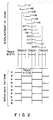
- different servo data patterns indicated by "A" and "B” in Fig. 2 extend on the opposite sides from the center of a track or a cylinder.
- patterns A and B are alternately read by magnetic head l0. Consequently, signals corresponding to those patterns A and B alternately appear.
- Magnetic head l0 reads out data, which has been recorded in advance on the disk so as to sequentially appear as the disk rotates.
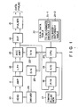
- a signal corresponding to the read data is supplied to an amplifier ll for amplification.
- the signal amplified by amplifier ll is supplied to a low-pass filter (LPF) l2, which filters out its low-frequency noise.
- the filtered signal is then supplied to an AGC amplifier l3, which is also supplied with gain data from a CPU 20 through D/A converter 22, in accordance with the position of a presently designated cylinder.
- LPF low-pass filter
- AGC amplifier l3 changes its gain in accordance with the received gain data, amplifies the signal from low-pass filter l2, and supplies the amplified signal to differential circuit (DIF) l4 as well as to peak hold circuit (P/H) l8.
- differential circuit l4 differentiates the signal from AGC amplifier l3 to detect the zero crossing point of the received signal.
- the output of differential circuit l4 is supplied to a pulser l5 where a data pulse is created based on the detected zero crossing point.
- Amplifier ll, low-pass filter l2, AGC amplifier l3, differential circuit l4 and pulser l5 constitute a data pulse generation section.
- Peak hold circuit l8 receives a timing pulse from timing pulse generator l7 in addition to the output of AGC amplifier l3. Peak hold circuit l8 holds the peak value of the amplified signal from AGC amplifier l3 in response to the timing pulse.
- a timing pulse for holding the peak value of the amplified signal corresponding to the servo data is supplied to peak hold circuit l8 from timing pulse generator l7.
- An A/D converter l9 converts the peak value held by peak hold circuit l8 into digital data and outputs it to CPU 20.
- the digital data corresponding to patterns A and B are sequentially supplied to CPU 20.
- Timing pulse generator l7, peak hold circuit l8 and A/D converter l9 constitute a servo data peak hold section.
- CPU 20 determines cylinder-dependent gain data for the position of the presently designated cylinder and outputs the gain data to AGC amplifier l3 through D/A converter 22.
- CPU 20 receives and holds digital data from A/D converter l9, e.g., a peak value A ⁇ corresponding to pattern A.
- CPU 20 then receives and holds a peak value B ⁇ that corresponds to pattern B following pattern A, and adds those peak values A ⁇ and B ⁇ Based on the added result A ⁇ +B ⁇ , CPU 20 refers to a to-be-changed amount table 2l-l of a gain data table 2l to attain the amount of a change that should be made to the gain data.
- gain data table 2l includes cylinder-dependent table 2l-2, which stores cylinder-dependent gain data for the cylinder position presently stored in a cylinder data storage region (not shown). The optimal gain data for the cylinder on which magnetic head l0 presently lies is attained from the amount of change in gain data change and the cylinder-dependent gain data.
- gain data is supplied to D/A converter 22 for analog conversion and is then supplied to AGC amplifier l3.
- the sum of the peak values of digital data corresponding to servo data patterns A and B is maintained approximately at a predetermined value by repeating the aforementioned operational sequence through the closed loop which is formed by the aforementioned peak hold circuit l8, A/D converter l9, CPU 20, D/A converter 22 and AGC amplifier l3.
- CPU 20 calculates the difference A ⁇ -B ⁇ between the peak values and outputs data corresponding to this difference to D/A converter 23.
- D/A converter 23 converts the received difference data into analog data and outputs it to driver 24. Based on the received analog data, driver 24 drives magnetic head l0 to position it at the proper cylinder location.
- a disk drive is powered on and the initializing procedures, such as detection of the position of the zero cylinder, are carried out.
- the recorded data reproducing apparatus is ready for receiving any command.
- step Sl6 it is determined whether or not the input command is a seek command, and if YES, the flow advances to step S30 where cylinder data specified by the seek command is stored in the cylinder data storage region. If NO in step Sl6, the flow advances to step Sl8 where this time, it is determined whether or not the input command is a write command. If the decision is affirmative in step Sl8, the flow advances to step S34, and if it is negative, the input command is determined to be a read command and the flow advances to step S20.
- Figs. 3A-3M illustrate the waveforms of the outputs from AGC amplifier l3 respectively for the positions Hl to Hl3 (see Fig. 2) of magnetic head l0.
- the input command is a seek command to move magnetic head l0 to cylinder or track 2 from cylinder or track l as shown in Fig. 2, the cylinder position specified by the seek command is stored in the cylinder data storage region in step S30.
- magnetic head l0 is moved to the designated cylinder position.
- step S34 When the input command is a write command, other processings are carried out in step S34.
- the cylinder position at which magnetic head l0 is presently located is read out from the cylinder data storage region in step S20.
- cylinder-dependent table 2l-2 Based on the readout cylinder position, cylinder-dependent table 2l-2 is referred to, thus providing cylinder-dependent gain data.
- This cylinder-dependent gain data is supplied through D/A converter 22 to AGC amplifier l3.
- step S22 it is determined whether or not the sum of two peak values A ⁇ and B ⁇ supplied through A/D converter l9 from peak hold circuit l8 is within a predetermined allowable error range ⁇ from a predetermined value C.
- step S24 is executed so that gain data to be output to AGC amplifier l3 is changed. More specifically, based on the sum of peak values A ⁇ and B ⁇ , gain data table 2l is referred to for determination of the to-be-changed amount of gain data, and this to-be-changed amount of gain data is coupled to the cylinder gain data. The resultant gain data is then supplied again to AGC amplifier l3 to optimize the gain thereof. Thereafter, step S22 is repeated, and if the decision is affirmative in this step, the subsequent step S26 is executed.
- step S26 it is checked if two peak values A ⁇ and B ⁇ are nearly equal to each other. If the determination in step S26 is negative, the flow advances to step S27. For instance, when magnetic head l0 is positioned at Hl2 in Fig. 2, peak value A ⁇ does not equal to peak value B ⁇ as shown in Fig. 3B. This is a natural consequence because the major portion of the detection region of magnetic head l0 with respect to the recording medium is on the side of pattern A. To cope with this peak imbalance, magnetic head l0 needs to be moved to the rightward in Fig. 2.
- CPU 20 calculates the difference between peak values A ⁇ and B ⁇ , or A ⁇ -B ⁇ , and outputs the calculation result to D/A converter 23.
- D/A converter 23 converts the received digital value into an analog value and then supplies it to driver 24. Based on the analog value (representing the calculation result from CPU 20), driver 24 moves magnetic head l0 to the proper position Hl3 in Fig. 2. The waveform of the resultant signal would have a nearly equal peak value for patterns A and B as shown in Fig. 3A. Thereafter, step S26 is executed again.
- step S28 recorded data following the servo data is read out from the cylinder on which magnetic head l0 is presently positioned.
- the output of AGC amplifier l3 is supplied to differential circuit l4 and then to pulser l5 where a data pulse is produced.
- the cylinder-dependent gain data is output first, when a read command is entered after magnetic head l0 is shifted by a seek command.
- This operation may be modified such that the gain data determined by the previous read command is stored and this stored gain data is output first when the next read command is entered. This modification can eliminate the need to use the cylinder-dependent table.
Landscapes
- Engineering & Computer Science (AREA)
- Signal Processing (AREA)
- Signal Processing For Digital Recording And Reproducing (AREA)
- Digital Magnetic Recording (AREA)
- Moving Of The Head To Find And Align With The Track (AREA)
- Indexing, Searching, Synchronizing, And The Amount Of Synchronization Travel Of Record Carriers (AREA)
- Adjustment Of The Magnetic Head Position Track Following On Tapes (AREA)
- Electrophonic Musical Instruments (AREA)
- Camera Data Copying Or Recording (AREA)
Priority Applications (1)
| Application Number | Priority Date | Filing Date | Title |
|---|---|---|---|
| AT87110625T ATE72495T1 (de) | 1986-07-30 | 1987-07-22 | Anordnung zur wiedergabe von aufgezeichneten daten. |
Applications Claiming Priority (2)
| Application Number | Priority Date | Filing Date | Title |
|---|---|---|---|
| JP177716/86 | 1986-07-30 | ||
| JP61177716A JPS6337815A (ja) | 1986-07-30 | 1986-07-30 | 記録デ−タ再生装置 |
Publications (3)
| Publication Number | Publication Date |
|---|---|
| EP0255036A2 true EP0255036A2 (de) | 1988-02-03 |
| EP0255036A3 EP0255036A3 (en) | 1988-10-19 |
| EP0255036B1 EP0255036B1 (de) | 1992-02-05 |
Family
ID=16035858
Family Applications (1)
| Application Number | Title | Priority Date | Filing Date |
|---|---|---|---|
| EP87110625A Expired - Lifetime EP0255036B1 (de) | 1986-07-30 | 1987-07-22 | Anordnung zur Wiedergabe von aufgezeichneten Daten |
Country Status (6)
| Country | Link |
|---|---|
| US (1) | US4794469A (de) |
| EP (1) | EP0255036B1 (de) |
| JP (1) | JPS6337815A (de) |
| KR (1) | KR900007670B1 (de) |
| AT (1) | ATE72495T1 (de) |
| DE (1) | DE3776603D1 (de) |
Cited By (2)
| Publication number | Priority date | Publication date | Assignee | Title |
|---|---|---|---|---|
| EP0363186A3 (en) * | 1988-10-05 | 1990-12-05 | Pioneer Electronic Corporation | Method for setting a sound recording level |
| WO1993019466A3 (en) * | 1992-03-18 | 1993-11-11 | Int Microelectronic Products | Computer disk drive integrated data path circuit optimized for handling both data and servo signals |
Families Citing this family (14)
| Publication number | Priority date | Publication date | Assignee | Title |
|---|---|---|---|---|
| US4984102A (en) * | 1987-08-31 | 1991-01-08 | Canon Kabushiki Kaisha | Information signal recording apparatus and apparatus for reproducing the same |
| JPH01236469A (ja) * | 1988-03-16 | 1989-09-21 | Pioneer Electron Corp | 情報記録再生装置 |
| EP0445780B1 (de) * | 1990-03-07 | 1997-07-09 | Canon Kabushiki Kaisha | System zum Aufzeichnen und Wiedergeben eines Bildsignals |
| KR940007943B1 (ko) * | 1990-06-29 | 1994-08-29 | 가부시기가이샤 도시바 | 자기헤드 이동속도 제어장치 |
| KR950001610B1 (ko) * | 1990-06-29 | 1995-02-27 | 가부시기가이샤 도시바 | 자기헤드 이동속도 제어장치 |
| US5416646A (en) * | 1992-11-12 | 1995-05-16 | Kabushiki Kaisha Toshiba | Data recording and reproducing apparatus having read/write circuit with programmable parameter means |
| US5392171A (en) * | 1993-01-07 | 1995-02-21 | Seagate Technology, Inc. | Fully integrated programmable filters for disc drive subsystems |
| US5467231A (en) * | 1993-02-26 | 1995-11-14 | Hewlett-Packard Company | Using recorded data for auto calibration of fixed gain of a read amplifier in a data storage device |
| JP2666747B2 (ja) * | 1994-12-14 | 1997-10-22 | 日本電気株式会社 | 磁気ディスク装置の磁気ヘッド位置決め回路 |
| JPH08212736A (ja) * | 1995-02-02 | 1996-08-20 | Toshiba Corp | 磁気ディスク装置におけるサーボ信号検出装置及びサーボ信号検出方法 |
| KR100277073B1 (ko) * | 1995-07-24 | 2001-01-15 | 윤종용 | 자기 디스크 구동장치에서 자기 헤드의 속도 및 위치 추정기 |
| US6965547B2 (en) * | 2001-01-25 | 2005-11-15 | Dphi Acquisitions, Inc. | Tracking and focus servo system with error signal inverse non-linearity calibration |
| US7522480B2 (en) | 2001-01-25 | 2009-04-21 | Dphi Acquisitions, Inc. | Digital tracking servo system with multi-track seek with an acceleration clamp |
| US20080229485A1 (en) * | 2007-03-22 | 2008-09-25 | Shannon Cooper | Garter with pouch for auxiliary items |
Family Cites Families (9)
| Publication number | Priority date | Publication date | Assignee | Title |
|---|---|---|---|---|
| US3593333A (en) * | 1969-11-26 | 1971-07-13 | Ibm | Position detection for a track following servo system |
| US3691543A (en) * | 1971-02-08 | 1972-09-12 | Ibm | Positioning system including servo track configuration and associated demodulator |
| US4544964A (en) * | 1978-02-24 | 1985-10-01 | Burroughs Corporation | Strobe for read/write chain |
| JPS5564661A (en) * | 1978-11-08 | 1980-05-15 | Toshiba Corp | Self-compensator for magnetic disk memory unit |
| US4298898A (en) * | 1979-04-19 | 1981-11-03 | Compagnie Internationale Pour L'informatique Cii Honeywell Bull | Method of and apparatus for reading data from reference zones of a memory |
| US4564867A (en) * | 1980-07-24 | 1986-01-14 | Universal Pioneer Corporation | Video disc recording and reproducing device for video discs having recognition signal indicative of content of associated program signal |
| DE3275670D1 (en) * | 1982-06-18 | 1987-04-16 | Ibm | Head positioning system with automatic gain control |
| US4480217A (en) * | 1982-12-14 | 1984-10-30 | Storage Technology Corporation | Automatic velocity calibrator for a velocity servo loop in a magnetic disk drive |
| JPS6117815A (ja) * | 1984-07-03 | 1986-01-25 | Mitsubishi Heavy Ind Ltd | バ−ナ噴霧蒸気供給装置 |
-
1986
- 1986-07-30 JP JP61177716A patent/JPS6337815A/ja active Pending
-
1987
- 1987-07-21 US US07/075,964 patent/US4794469A/en not_active Expired - Fee Related
- 1987-07-22 DE DE8787110625T patent/DE3776603D1/de not_active Expired - Lifetime
- 1987-07-22 EP EP87110625A patent/EP0255036B1/de not_active Expired - Lifetime
- 1987-07-22 AT AT87110625T patent/ATE72495T1/de active
- 1987-07-30 KR KR1019870008307A patent/KR900007670B1/ko not_active Expired
Cited By (3)
| Publication number | Priority date | Publication date | Assignee | Title |
|---|---|---|---|---|
| EP0363186A3 (en) * | 1988-10-05 | 1990-12-05 | Pioneer Electronic Corporation | Method for setting a sound recording level |
| WO1993019466A3 (en) * | 1992-03-18 | 1993-11-11 | Int Microelectronic Products | Computer disk drive integrated data path circuit optimized for handling both data and servo signals |
| US5463603A (en) * | 1992-03-18 | 1995-10-31 | Imp, Inc. | Computer disk drive integrated data path circuit optimized for handling both data and servo signals |
Also Published As
| Publication number | Publication date |
|---|---|
| ATE72495T1 (de) | 1992-02-15 |
| KR900007670B1 (ko) | 1990-10-18 |
| EP0255036A3 (en) | 1988-10-19 |
| EP0255036B1 (de) | 1992-02-05 |
| KR880002171A (ko) | 1988-04-29 |
| JPS6337815A (ja) | 1988-02-18 |
| DE3776603D1 (de) | 1992-03-19 |
| US4794469A (en) | 1988-12-27 |
Similar Documents
| Publication | Publication Date | Title |
|---|---|---|
| EP0255036A2 (de) | Anordnung zur Wiedergabe von aufgezeichneten Daten | |
| US7362536B1 (en) | Disk drive that compensates for phase incoherence between radially adjacent servo tracks and methods thereof | |
| US5691857A (en) | Method using matched filters for determining head positioner micro-jog in hard disk drive employing magneto-resistive heads | |
| JP2592202B2 (ja) | Prmlデータ・チャンネルにおける事前補償値を決定する方法及び装置 | |
| KR100518293B1 (ko) | 자기 디스크 장치 및 회전 동기 진동의 제어 방법 | |
| KR100881190B1 (ko) | 하드 디스크 드라이브 및 하드 디스크 드라이브의 서보 조정 방법 | |
| US20020089779A1 (en) | Reducing disc drive position error signal nonlinearity through iterative calibration of a compensation table | |
| KR100277073B1 (ko) | 자기 디스크 구동장치에서 자기 헤드의 속도 및 위치 추정기 | |
| KR100290604B1 (ko) | 자기디스크드라이브에 있어서 인텔리전트 트랙피치 조정방법 | |
| US5453888A (en) | Servo signal noise suppression in a sectored servo system by separating user data from servo data and filtering each with a specific filter | |
| KR100572944B1 (ko) | 판독/기록데이터인터페이스 | |
| US6072654A (en) | Frequency domain head linearization | |
| JPH08126370A (ja) | 磁気ディスク装置のマルチレートサンプルレートの共振抑制方式 | |
| US6226139B1 (en) | Clock generator and disk drive | |
| US5661617A (en) | Head positioning control system | |
| JPH11195280A (ja) | ディスク記憶装置および同装置に適用するヘッド位置制御システム | |
| JPS63131385A (ja) | デ−タトラックに対するデ−タ書込/取出し装置 | |
| JPH0714107A (ja) | 磁気ディスク装置及び記録電流設定方法 | |
| JP2601812B2 (ja) | 磁気ディスク装置 | |
| US6714378B1 (en) | Positioning method, positioning device and disk device | |
| JPH0997401A (ja) | データ記録再生装置用衝撃検出回路、同衝撃検出回路を有するデータ記録再生装置、及び同衝撃検出回路に適用するフィルタの感度設定方法 | |
| JP3788664B2 (ja) | 記録再生装置 | |
| JPH09147508A (ja) | ディスク装置及びディスク装置のヘッド位置決め制御方法 | |
| JPH05174514A (ja) | データ記録再生装置のヘッド位置決め制御装置 | |
| JPS63273284A (ja) | 磁気記録再生装置のサ−ボ方式 |
Legal Events
| Date | Code | Title | Description |
|---|---|---|---|
| PUAI | Public reference made under article 153(3) epc to a published international application that has entered the european phase |
Free format text: ORIGINAL CODE: 0009012 |
|
| 17P | Request for examination filed |
Effective date: 19870819 |
|
| AK | Designated contracting states |
Kind code of ref document: A2 Designated state(s): AT DE FR GB IT |
|
| PUAL | Search report despatched |
Free format text: ORIGINAL CODE: 0009013 |
|
| AK | Designated contracting states |
Kind code of ref document: A3 Designated state(s): AT DE FR GB IT |
|
| RIN1 | Information on inventor provided before grant (corrected) |
Inventor name: ASAI, KENJI Inventor name: KAIDA, KATSUHIKO C/O PATENT DIVISION |
|
| 17Q | First examination report despatched |
Effective date: 19890302 |
|
| GRAA | (expected) grant |
Free format text: ORIGINAL CODE: 0009210 |
|
| AK | Designated contracting states |
Kind code of ref document: B1 Designated state(s): AT DE FR GB IT |
|
| REF | Corresponds to: |
Ref document number: 72495 Country of ref document: AT Date of ref document: 19920215 Kind code of ref document: T |
|
| ITF | It: translation for a ep patent filed | ||
| REF | Corresponds to: |
Ref document number: 3776603 Country of ref document: DE Date of ref document: 19920319 |
|
| ET | Fr: translation filed | ||
| PLBE | No opposition filed within time limit |
Free format text: ORIGINAL CODE: 0009261 |
|
| STAA | Information on the status of an ep patent application or granted ep patent |
Free format text: STATUS: NO OPPOSITION FILED WITHIN TIME LIMIT |
|
| 26N | No opposition filed | ||
| PGFP | Annual fee paid to national office [announced via postgrant information from national office to epo] |
Ref country code: FR Payment date: 19970709 Year of fee payment: 11 |
|
| PGFP | Annual fee paid to national office [announced via postgrant information from national office to epo] |
Ref country code: GB Payment date: 19970714 Year of fee payment: 11 |
|
| PGFP | Annual fee paid to national office [announced via postgrant information from national office to epo] |
Ref country code: AT Payment date: 19970715 Year of fee payment: 11 |
|
| PGFP | Annual fee paid to national office [announced via postgrant information from national office to epo] |
Ref country code: DE Payment date: 19970725 Year of fee payment: 11 |
|
| PG25 | Lapsed in a contracting state [announced via postgrant information from national office to epo] |
Ref country code: GB Free format text: LAPSE BECAUSE OF NON-PAYMENT OF DUE FEES Effective date: 19980722 Ref country code: AT Free format text: LAPSE BECAUSE OF NON-PAYMENT OF DUE FEES Effective date: 19980722 |
|
| GBPC | Gb: european patent ceased through non-payment of renewal fee |
Effective date: 19980722 |
|
| PG25 | Lapsed in a contracting state [announced via postgrant information from national office to epo] |
Ref country code: FR Free format text: LAPSE BECAUSE OF NON-PAYMENT OF DUE FEES Effective date: 19990331 |
|
| PG25 | Lapsed in a contracting state [announced via postgrant information from national office to epo] |
Ref country code: DE Free format text: LAPSE BECAUSE OF NON-PAYMENT OF DUE FEES Effective date: 19990501 |
|
| REG | Reference to a national code |
Ref country code: FR Ref legal event code: ST |
|
| PG25 | Lapsed in a contracting state [announced via postgrant information from national office to epo] |
Ref country code: IT Free format text: LAPSE BECAUSE OF NON-PAYMENT OF DUE FEES;WARNING: LAPSES OF ITALIAN PATENTS WITH EFFECTIVE DATE BEFORE 2007 MAY HAVE OCCURRED AT ANY TIME BEFORE 2007. THE CORRECT EFFECTIVE DATE MAY BE DIFFERENT FROM THE ONE RECORDED. Effective date: 20050722 |