EP0255071A2 - Chenille du type bitubulaire pour véhicules - Google Patents
Chenille du type bitubulaire pour véhicules Download PDFInfo
- Publication number
- EP0255071A2 EP0255071A2 EP87110806A EP87110806A EP0255071A2 EP 0255071 A2 EP0255071 A2 EP 0255071A2 EP 87110806 A EP87110806 A EP 87110806A EP 87110806 A EP87110806 A EP 87110806A EP 0255071 A2 EP0255071 A2 EP 0255071A2
- Authority
- EP
- European Patent Office
- Prior art keywords
- tubular body
- connector
- approximately
- chain
- track according
- Prior art date
- Legal status (The legal status is an assumption and is not a legal conclusion. Google has not performed a legal analysis and makes no representation as to the accuracy of the status listed.)
- Granted
Links
- 239000010410 layer Substances 0.000 claims 1
- 238000004519 manufacturing process Methods 0.000 claims 1
- 239000002344 surface layer Substances 0.000 claims 1
- 238000005452 bending Methods 0.000 description 4
- 238000011161 development Methods 0.000 description 1
- 230000018109 developmental process Effects 0.000 description 1
- 230000000630 rising effect Effects 0.000 description 1
- 230000009291 secondary effect Effects 0.000 description 1
Images

Classifications
-
- B—PERFORMING OPERATIONS; TRANSPORTING
- B62—LAND VEHICLES FOR TRAVELLING OTHERWISE THAN ON RAILS
- B62D—MOTOR VEHICLES; TRAILERS
- B62D55/00—Endless track vehicles
- B62D55/08—Endless track units; Parts thereof
-
- B—PERFORMING OPERATIONS; TRANSPORTING
- B62—LAND VEHICLES FOR TRAVELLING OTHERWISE THAN ON RAILS
- B62D—MOTOR VEHICLES; TRAILERS
- B62D55/00—Endless track vehicles
- B62D55/08—Endless track units; Parts thereof
- B62D55/18—Tracks
- B62D55/20—Tracks of articulated type, e.g. chains
- B62D55/205—Connections between track links
- B62D55/21—Links connected by transverse pivot pins
- B62D55/211—Bitubular chain links assembled by pins and double connectors
Definitions
- the invention relates to a caterpillar track according to the connector principle for vehicles according to the preamble of claim 1.
- the invention is therefore based on the object of reducing the chain weight while maintaining the operational safety of known track chains according to the connector principle.
- the meshing of the drive gear does not take place, as was previously the case, on the external connectors of the track chain, but in the chain body between the tubes and laterally between two webs for lateral guidance of the drive gear.
- the wear surfaces of the tubular body which come into contact with the drive gear, are provided with an outer layer hardening to achieve a high wear resistance.
- the hardness depth extends from the tooth flank surface for the driving tooth to approximately the hole for the bolt.
- the tubular body is therefore ready for use until the entire hard layer is removed and only a small, non-hardened zone of the remaining wall thickness is present without the risk that the tubular body will tear and thus become unusable.
- the tube wall area which is made available as a wear volume according to this principle, has to transmit chain tensile forces only to a very small extent and can therefore be worn to a minimum.
- the bolt diameter is significantly smaller than previously known designs. This has the secondary effect that the chain body is correspondingly lower and therefore lighter with the same thickness of the rubber mounting for the bolt.
- the elastic bearing length of the bolts in the tubular body is substantially coarser, namely between 3 and 5%, since the external connectors are made much narrower than previous designs. According to the invention there is a 5 to 7% longer bearing length for the bolts.
- the wall thicknesses in the loop area are designed so that the forces to be transmitted are reliably transmitted during operation of the chain.
- the connector has the function of a band clamp that encloses the bolt with a uniform tangential force without any noteworthy bending. A low clamping force and thus a smaller and lighter screw is sufficient for fastening. Therefore, the assembly forces are smaller and therefore the connector is quicker and easier to assemble than according to the prior art.
- the tube body with its two openings for the engagement of the drive gears between the tube sections is essential for the invention.
- This measure results in a weight saving of 8 to 10% on the tubular body despite the approximately 3-5% larger width of the tubular body.
- the wider tubular body significantly increases the footprint of the chain on the ground, so that the ground pressure is correspondingly low.
- This increases the mobility of a vehicle in the field with the same vehicle drive power; the same applies to driving on the road.
- This measure also has the result that the bolts are loaded more favorably by the introduction of force directly into the tubular body and the connectors are completely relieved of the meshing of the drive teeth.
- the entire measures lead to a weight saving of approx. 14%, corresponding to a weight saving for a vehicle of approx. 750 kg.
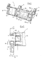
- a tubular body 1 of a track chain, not shown, according to the connector principle is provided with continuous bolts 3, which are mounted in tubes 2, and connectors 4 fastened to them on the outside and a center connector 5.
- the rubber bearings are designated 8.
- Openings 6 for the tooth 18 of a drive gear 19 are delimited by the tubes 2 and by webs 7.
- One-piece, hardened wear cams 10 with kidney-shaped surface hardening zones 11 are provided on the tubes 2.
- the wider sections 12 lie at the narrowest cross section 13 of the opening 6.
- the main axes 14 of the hardening zones 11 form a V shape.
- the average radius 16 for the outer contour of the hardening zone 11 corresponds approximately to the inner diameter 17 of the tubes 2.
- a tooth 18 of a driving ring 19 engages in the drive tooth engagement 6 according to FIG. 3.
- Gripper bars 20 with guide grooves 21 and stop bars 22 for an insertable running pad 23 as well as an H-shaped central part 46 and base plates 25 are provided on the tubular body 1.
- the middle part 46 has recesses 45 for inserting the center connector 5.
- the free bolt sections 30 have a length 31 which corresponds to approximately 1.4 times the diameter 32 of the bolt 3.
- the wall thickness 35 of the connector 4 is approximately 25% of the bolt diameter 32, the bearing length 36 corresponds to approximately 1.3 times the bolt diameter 32. Because of the necessary frictional connection between the bolt 3 and the connector 4, the equally thick support plates 37 have a 30 % greater wall thickness 38 than the wall thickness 35. The frictional connection is generated via the screw connection 48 in a bore 39.
- a distance 47 between the center of the opening 6 and the center of the connector 4 is very small. In between there is only a web 7. This small distance 47 leads to a relatively low load on the bolt 3 when a caterpillar is in operation.
- a tubular body 51 provided with running pads 50 has openings 6 in the tubular body 51, specifically within the running pads 50.
- the running pads 50 are provided with continuous recesses 52 for the removal of dirt.
- Crosspieces 7 laterally limit the openings 6 and the tubes 2 in the running direction 53.
- a relatively large distance 54 exists between the openings 6 and the connector 4.
Landscapes
- Engineering & Computer Science (AREA)
- Chemical & Material Sciences (AREA)
- Combustion & Propulsion (AREA)
- Transportation (AREA)
- Mechanical Engineering (AREA)
- Gears, Cams (AREA)
- Devices For Conveying Motion By Means Of Endless Flexible Members (AREA)
- Escalators And Moving Walkways (AREA)
- Road Paving Structures (AREA)
- Connector Housings Or Holding Contact Members (AREA)
- Superconductors And Manufacturing Methods Therefor (AREA)
- Shaping Of Tube Ends By Bending Or Straightening (AREA)
- Platform Screen Doors And Railroad Systems (AREA)
- Radar Systems Or Details Thereof (AREA)
- Details Of Connecting Devices For Male And Female Coupling (AREA)
- Vehicle Body Suspensions (AREA)
- Connections By Means Of Piercing Elements, Nuts, Or Screws (AREA)
- Arrangement Or Mounting Of Control Devices For Change-Speed Gearing (AREA)
- Lighting Device Outwards From Vehicle And Optical Signal (AREA)
- Traffic Control Systems (AREA)
- Supports For Pipes And Cables (AREA)
- Mechanical Coupling Of Light Guides (AREA)
- Transition And Organic Metals Composition Catalysts For Addition Polymerization (AREA)
Priority Applications (1)
| Application Number | Priority Date | Filing Date | Title |
|---|---|---|---|
| AT87110806T ATE58100T1 (de) | 1986-07-28 | 1987-07-25 | Gleiskette nach dem verbinderprinzip fuer fahrzeuge. |
Applications Claiming Priority (2)
| Application Number | Priority Date | Filing Date | Title |
|---|---|---|---|
| DE3625491 | 1986-07-28 | ||
| DE19863625491 DE3625491A1 (de) | 1986-07-28 | 1986-07-28 | Gleiskette nach dem verbinderprinzip fuer fahrzeuge |
Publications (4)
| Publication Number | Publication Date |
|---|---|
| EP0255071A2 true EP0255071A2 (fr) | 1988-02-03 |
| EP0255071A3 EP0255071A3 (en) | 1988-06-08 |
| EP0255071B1 EP0255071B1 (fr) | 1990-11-07 |
| EP0255071B2 EP0255071B2 (fr) | 1994-09-07 |
Family
ID=6306140
Family Applications (1)
| Application Number | Title | Priority Date | Filing Date |
|---|---|---|---|
| EP87110806A Expired - Lifetime EP0255071B2 (fr) | 1986-07-28 | 1987-07-25 | Chenille du type bitubulaire pour véhicules |
Country Status (13)
| Country | Link |
|---|---|
| US (1) | US4813750A (fr) |
| EP (1) | EP0255071B2 (fr) |
| JP (1) | JP2533544B2 (fr) |
| KR (1) | KR960016588B1 (fr) |
| AT (1) | ATE58100T1 (fr) |
| AU (1) | AU585458B2 (fr) |
| BR (1) | BR8702760A (fr) |
| CA (1) | CA1310681C (fr) |
| DE (2) | DE3625491A1 (fr) |
| ES (1) | ES2019345T5 (fr) |
| GR (1) | GR3001437T3 (fr) |
| IL (1) | IL83255A (fr) |
| TR (1) | TR23699A (fr) |
Cited By (1)
| Publication number | Priority date | Publication date | Assignee | Title |
|---|---|---|---|---|
| GB2225991A (en) * | 1988-11-25 | 1990-06-20 | Fmc Corp | Explosion resistant track shoe for track-laying vehicles |
Families Citing this family (15)
| Publication number | Priority date | Publication date | Assignee | Title |
|---|---|---|---|---|
| DE19613412C2 (de) * | 1996-04-03 | 2002-07-04 | Krauss Maffei Wegmann Gmbh & C | Gleiskette |
| DE19619577C2 (de) * | 1996-05-15 | 1998-12-03 | Diehl Remscheid Gmbh & Co | Verbindergleiskette mit Laufpolster |
| US6447077B1 (en) * | 2000-08-08 | 2002-09-10 | Loegering Mfg. Inc. | Lift link flexible track |
| DE10130386A1 (de) | 2001-06-23 | 2003-01-02 | Diehl Remscheid Gmbh & Co | Gleiskette nach dem Verbinderprinzip |
| AUPS238002A0 (en) * | 2002-05-17 | 2002-06-13 | Mackay Consolidated Industries Pty. Ltd. | Vehicle track chain and link therefor |
| DE10354486B3 (de) * | 2003-11-21 | 2005-03-03 | Bundesrepublik Deutschland, vertreten durch Bundesministerium der Verteidigung, vertreten durch Bundesamt für Wehrtechnik und Beschaffung | Traktionskörper zur Anbringung auf ein Laufpolster einer Gleiskette |
| EP1772291B1 (fr) * | 2004-07-30 | 2010-01-13 | Kabushiki Kaisha Box | Roulette |
| CN1740023B (zh) * | 2004-08-27 | 2011-07-13 | 株式会社小松制作所 | 链节及其制造方法 |
| US20080018173A1 (en) * | 2006-07-21 | 2008-01-24 | John David Kremer | Rubberized segmented track |
| CN100589921C (zh) * | 2008-06-24 | 2010-02-17 | 中国第一冶金建设有限责任公司 | 箱形履带机构的修复方法 |
| US8511760B2 (en) | 2010-10-06 | 2013-08-20 | Gse Technologies, Llc | Roller bearing track bushing system |
| DE102014002358B4 (de) | 2014-02-18 | 2015-10-29 | Bundesrepublik Deutschland, vertreten durch das BMVg, vertreten durch das Bundesamt für Ausrüstung, Informationstechnik und Nutzung der Bundeswehr | Kettenkörper für Gleisketten |
| DE102014018657B4 (de) * | 2014-12-13 | 2017-03-23 | DST Defence Service Tracks GmbH | Gleiskette |
| DE102016003351B4 (de) * | 2016-03-18 | 2023-03-23 | Bundesrepublik Deutschland, vertr. durch das Bundesministerium der Verteidigung, vertr. durch das Bundesamt für Ausrüstung, Informationstechnik und Nutzung der Bundeswehr | Traktionshilfe für Gleisketten |
| US20220315138A1 (en) * | 2021-04-02 | 2022-10-06 | Robotzone, Llc | Track assembly for hobby robotics |
Family Cites Families (9)
| Publication number | Priority date | Publication date | Assignee | Title |
|---|---|---|---|---|
| US2392383A (en) * | 1943-03-20 | 1946-01-08 | Theodore J Hollenkamp | Track for track-laying vehicles |
| FR1363977A (fr) * | 1963-04-17 | 1964-06-19 | Diehl K G Fa | Chenille dont les éléments sont munis d'un revêtement en caoutchouc sur une face ou sur deux faces |
| DE1480750A1 (de) * | 1963-09-14 | 1969-07-24 | Diehl Kg | Gleiskettenverbindungsglied |
| US3340717A (en) * | 1964-07-11 | 1967-09-12 | Diehl K G | Method of making caterpillar track connectors |
| DE1480778A1 (de) * | 1965-07-28 | 1969-07-03 | Gerlach Werke Gmbh | Gleiskette fuer gelaendegaengige Fahrzeuge,insbesondere Panzerkampfwagen |
| DE1605523C3 (de) * | 1967-06-30 | 1975-07-03 | Gerlach-Werke Gmbh, 6650 Homburg | Verbindergleiskette für geländegängige Fahrzeuge, insbesondere Panzerkampfwagen |
| GB1556872A (en) * | 1975-12-06 | 1979-11-28 | Gerlach Werke Gmbh | Track construction for tracked land vehicles such as tanks |
| JPS606831A (ja) * | 1983-06-24 | 1985-01-14 | Shimadzu Corp | 分光光度計 |
| SU1186991A1 (ru) * | 1984-03-29 | 1985-10-23 | Киевское Высшее Танковое Инженерное Ордена Красной Звезды Училище Им.Маршала Советского Союза Якубовского И.И. | Устройство дл замера реакций грунта при движении гусеничной машины |
-
1986
- 1986-07-28 DE DE19863625491 patent/DE3625491A1/de not_active Withdrawn
-
1987
- 1987-05-29 BR BR8702760A patent/BR8702760A/pt not_active IP Right Cessation
- 1987-06-13 JP JP62147814A patent/JP2533544B2/ja not_active Expired - Lifetime
- 1987-06-18 US US07/064,220 patent/US4813750A/en not_active Expired - Lifetime
- 1987-07-10 AU AU75529/87A patent/AU585458B2/en not_active Expired
- 1987-07-20 IL IL83255A patent/IL83255A/xx not_active IP Right Cessation
- 1987-07-24 TR TR87/0538A patent/TR23699A/xx unknown
- 1987-07-25 DE DE8787110806T patent/DE3766033D1/de not_active Expired - Lifetime
- 1987-07-25 ES ES87110806T patent/ES2019345T5/es not_active Expired - Lifetime
- 1987-07-25 KR KR1019870008120A patent/KR960016588B1/ko not_active Expired - Fee Related
- 1987-07-25 EP EP87110806A patent/EP0255071B2/fr not_active Expired - Lifetime
- 1987-07-25 AT AT87110806T patent/ATE58100T1/de not_active IP Right Cessation
- 1987-07-27 CA CA000543060A patent/CA1310681C/fr not_active Expired - Lifetime
-
1991
- 1991-02-06 GR GR91400150T patent/GR3001437T3/el unknown
Cited By (1)
| Publication number | Priority date | Publication date | Assignee | Title |
|---|---|---|---|---|
| GB2225991A (en) * | 1988-11-25 | 1990-06-20 | Fmc Corp | Explosion resistant track shoe for track-laying vehicles |
Also Published As
| Publication number | Publication date |
|---|---|
| JPS6338086A (ja) | 1988-02-18 |
| GR3001437T3 (en) | 1992-09-25 |
| BR8702760A (pt) | 1988-03-01 |
| CA1310681C (fr) | 1992-11-24 |
| AU585458B2 (en) | 1989-06-15 |
| EP0255071B1 (fr) | 1990-11-07 |
| EP0255071A3 (en) | 1988-06-08 |
| ES2019345T5 (es) | 1995-08-16 |
| IL83255A (en) | 1991-06-10 |
| ES2019345B3 (es) | 1991-06-16 |
| TR23699A (tr) | 1990-06-29 |
| KR960016588B1 (ko) | 1996-12-16 |
| DE3625491A1 (de) | 1988-02-04 |
| ATE58100T1 (de) | 1990-11-15 |
| KR880001483A (ko) | 1988-04-23 |
| EP0255071B2 (fr) | 1994-09-07 |
| AU7552987A (en) | 1988-02-04 |
| US4813750A (en) | 1989-03-21 |
| JP2533544B2 (ja) | 1996-09-11 |
| DE3766033D1 (de) | 1990-12-13 |
Similar Documents
| Publication | Publication Date | Title |
|---|---|---|
| EP0255071B1 (fr) | Chenille du type bitubulaire pour véhicules | |
| EP0512467B1 (fr) | Système de propulsion pour véhicule à chenilles | |
| DE69705008T2 (de) | Treibkette, insbesondere für Fahrrad | |
| DE69914024T2 (de) | Zahnkette mit Kippgelenken mit einem dickeren Gelenkbolzen als zu einem zugehörigen Kippbolzen | |
| DE2720332A1 (de) | Raupenfahrwerk | |
| EP0767315B1 (fr) | Palier de vilebrequin pour moteur à combustion | |
| DE10211308B4 (de) | Zahnkette | |
| DE3235474A1 (de) | Kette zum uebertragen grosser kraefte und hoher leistungen | |
| WO1995021089A1 (fr) | Palier elastique pour boulons de chenilles | |
| DE2755412C3 (de) | Vorrichtung zur Verbindung von Kettkörpern einer Gleiskette | |
| DE3016151A1 (de) | Vorrichtung zum befestigen von schmiedestuecken auf einer oder mehreren rundstahlketten | |
| DE102007025495A1 (de) | Beidseitig wirkende Zahnkette | |
| EP0966625B1 (fr) | Joint de chaine | |
| DE112019004089T5 (de) | Flexible kettenplatte für eine schwermaschinengleiskette und verfahren zur herstellung einer flexiblen kettenplatte | |
| DE2533793C3 (de) | Gleiskette | |
| DE102010009971A1 (de) | Kettenglied | |
| EP0180698B1 (fr) | Chenille pour véhicules de chantier ou similaires | |
| DE3239099A1 (de) | Traktionskette fuer die antriebsraeder eines radfahrzeuges | |
| DE3920003C2 (de) | Einteiliges Kettenglied | |
| DE3802914C2 (fr) | ||
| EP0115570B1 (fr) | Chenille pour véhicule tous-terrains | |
| DE2727578A1 (de) | Umlenkrad mit kettenzaehnen fuer laschenketten | |
| DE7100486U (de) | Kettenrad für Raupenfahrzeuge, insbesondere Pistenfahrzeuge | |
| EP0331069A1 (fr) | Tête de suspension pour élingues à chaîne | |
| DE3510350A1 (de) | Spurbuegel fuer ketten von pistenfahrzeugen |
Legal Events
| Date | Code | Title | Description |
|---|---|---|---|
| PUAI | Public reference made under article 153(3) epc to a published international application that has entered the european phase |
Free format text: ORIGINAL CODE: 0009012 |
|
| AK | Designated contracting states |
Kind code of ref document: A2 Designated state(s): AT BE CH DE ES FR GB GR IT LI NL SE |
|
| PUAL | Search report despatched |
Free format text: ORIGINAL CODE: 0009013 |
|
| AK | Designated contracting states |
Kind code of ref document: A3 Designated state(s): AT BE CH DE ES FR GB GR IT LI NL SE |
|
| 17P | Request for examination filed |
Effective date: 19880618 |
|
| 17Q | First examination report despatched |
Effective date: 19890802 |
|
| GRAA | (expected) grant |
Free format text: ORIGINAL CODE: 0009210 |
|
| AK | Designated contracting states |
Kind code of ref document: B1 Designated state(s): AT BE CH DE ES FR GB GR IT LI NL SE |
|
| REF | Corresponds to: |
Ref document number: 58100 Country of ref document: AT Date of ref document: 19901115 Kind code of ref document: T |
|
| REF | Corresponds to: |
Ref document number: 3766033 Country of ref document: DE Date of ref document: 19901213 |
|
| ITF | It: translation for a ep patent filed | ||
| GBT | Gb: translation of ep patent filed (gb section 77(6)(a)/1977) | ||
| ET | Fr: translation filed | ||
| ITTA | It: last paid annual fee | ||
| PLBI | Opposition filed |
Free format text: ORIGINAL CODE: 0009260 |
|
| 26 | Opposition filed |
Opponent name: BUNDESREPUBLIK DEUTSCHLAND, DIESE VERTRETEN DURCH Effective date: 19910801 |
|
| NLR1 | Nl: opposition has been filed with the epo |
Opponent name: BUNDESREPUBLIK DEUTSCHLAND(BUNDESAMT FUER WEHRTECH |
|
| REG | Reference to a national code |
Ref country code: GR Ref legal event code: FG4A Free format text: 3001437 |
|
| PUAA | Information related to the publication of a b2 document modified |
Free format text: ORIGINAL CODE: 0009299PMAP |
|
| PUAH | Patent maintained in amended form |
Free format text: ORIGINAL CODE: 0009272 |
|
| STAA | Information on the status of an ep patent application or granted ep patent |
Free format text: STATUS: PATENT MAINTAINED AS AMENDED |
|
| 27A | Patent maintained in amended form |
Effective date: 19940907 |
|
| AK | Designated contracting states |
Kind code of ref document: B2 Designated state(s): SE |
|
| R27A | Patent maintained in amended form (corrected) |
Effective date: 19940907 |
|
| NLR2 | Nl: decision of opposition | ||
| PG25 | Lapsed in a contracting state [announced via postgrant information from national office to epo] |
Ref country code: GR Free format text: THE PATENT HAS BEEN ANNULLED BY A DECISION OF A NATIONAL AUTHORITY Effective date: 19941129 |
|
| ITF | It: translation for a ep patent filed | ||
| ET3 | Fr: translation filed ** decision concerning opposition | ||
| GBTA | Gb: translation of amended ep patent filed (gb section 77(6)(b)/1977) |
Effective date: 19941130 |
|
| NLR3 | Nl: receipt of modified translations in the netherlands language after an opposition procedure | ||
| EAL | Se: european patent in force in sweden |
Ref document number: 87110806.4 |
|
| REG | Reference to a national code |
Ref country code: GR Ref legal event code: FG4A Free format text: 3014138 |
|
| REG | Reference to a national code |
Ref country code: ES Ref legal event code: DC2A Kind code of ref document: T5 Effective date: 19950816 |
|
| NLT1 | Nl: modifications of names registered in virtue of documents presented to the patent office pursuant to art. 16 a, paragraph 1 |
Owner name: DIEHL STIFTUNG & CO. |
|
| REG | Reference to a national code |
Ref country code: ES Ref legal event code: PC2A |
|
| REG | Reference to a national code |
Ref country code: GB Ref legal event code: IF02 |
|
| APAH | Appeal reference modified |
Free format text: ORIGINAL CODE: EPIDOSCREFNO |
|
| PGFP | Annual fee paid to national office [announced via postgrant information from national office to epo] |
Ref country code: GR Payment date: 20060530 Year of fee payment: 20 |
|
| PGFP | Annual fee paid to national office [announced via postgrant information from national office to epo] |
Ref country code: BE Payment date: 20060531 Year of fee payment: 20 Ref country code: FR Payment date: 20060531 Year of fee payment: 20 |
|
| PGFP | Annual fee paid to national office [announced via postgrant information from national office to epo] |
Ref country code: AT Payment date: 20060703 Year of fee payment: 20 |
|
| PGFP | Annual fee paid to national office [announced via postgrant information from national office to epo] |
Ref country code: ES Payment date: 20060705 Year of fee payment: 20 |
|
| PGFP | Annual fee paid to national office [announced via postgrant information from national office to epo] |
Ref country code: GB Payment date: 20060714 Year of fee payment: 20 |
|
| PGFP | Annual fee paid to national office [announced via postgrant information from national office to epo] |
Ref country code: NL Payment date: 20060728 Year of fee payment: 20 |
|
| PGFP | Annual fee paid to national office [announced via postgrant information from national office to epo] |
Ref country code: IT Payment date: 20060731 Year of fee payment: 20 |
|
| PGFP | Annual fee paid to national office [announced via postgrant information from national office to epo] |
Ref country code: CH Payment date: 20060804 Year of fee payment: 20 |
|
| PGFP | Annual fee paid to national office [announced via postgrant information from national office to epo] |
Ref country code: DE Payment date: 20060912 Year of fee payment: 20 |
|
| PG25 | Lapsed in a contracting state [announced via postgrant information from national office to epo] |
Ref country code: NL Free format text: LAPSE BECAUSE OF EXPIRATION OF PROTECTION Effective date: 20070725 |
|
| REG | Reference to a national code |
Ref country code: GB Ref legal event code: PE20 |
|
| REG | Reference to a national code |
Ref country code: CH Ref legal event code: PL |
|
| EUG | Se: european patent has lapsed | ||
| NLV7 | Nl: ceased due to reaching the maximum lifetime of a patent |
Effective date: 20070725 |
|
| REG | Reference to a national code |
Ref country code: ES Ref legal event code: FD2A Effective date: 20070726 |
|
| PG25 | Lapsed in a contracting state [announced via postgrant information from national office to epo] |
Ref country code: GB Free format text: LAPSE BECAUSE OF EXPIRATION OF PROTECTION Effective date: 20070724 |
|
| BE20 | Be: patent expired |
Owner name: *DIEHL STIFTUNG & CO. Effective date: 20070725 |
|
| PG25 | Lapsed in a contracting state [announced via postgrant information from national office to epo] |
Ref country code: ES Free format text: LAPSE BECAUSE OF EXPIRATION OF PROTECTION Effective date: 20070726 |
|
| PGFP | Annual fee paid to national office [announced via postgrant information from national office to epo] |
Ref country code: SE Payment date: 20060727 Year of fee payment: 20 |