EP0256487A2 - Verfahren und Vorrichtung zum Kontrollieren des Schusseintrags - Google Patents
Verfahren und Vorrichtung zum Kontrollieren des Schusseintrags Download PDFInfo
- Publication number
- EP0256487A2 EP0256487A2 EP87111592A EP87111592A EP0256487A2 EP 0256487 A2 EP0256487 A2 EP 0256487A2 EP 87111592 A EP87111592 A EP 87111592A EP 87111592 A EP87111592 A EP 87111592A EP 0256487 A2 EP0256487 A2 EP 0256487A2
- Authority
- EP
- European Patent Office
- Prior art keywords
- picking
- checking pin
- yarn package
- weft yarn
- time
- Prior art date
- Legal status (The legal status is an assumption and is not a legal conclusion. Google has not performed a legal analysis and makes no representation as to the accuracy of the status listed.)
- Granted
Links
Images

Classifications
-
- D—TEXTILES; PAPER
- D03—WEAVING
- D03D—WOVEN FABRICS; METHODS OF WEAVING; LOOMS
- D03D47/00—Looms in which bulk supply of weft does not pass through shed, e.g. shuttleless looms, gripper shuttle looms, dummy shuttle looms
- D03D47/34—Handling the weft between bulk storage and weft-inserting means
- D03D47/36—Measuring and cutting the weft
- D03D47/361—Drum-type weft feeding devices
- D03D47/362—Drum-type weft feeding devices with yarn retaining devices, e.g. stopping pins
- D03D47/363—Construction or control of the yarn retaining devices
-
- D—TEXTILES; PAPER
- D03—WEAVING
- D03D—WOVEN FABRICS; METHODS OF WEAVING; LOOMS
- D03D47/00—Looms in which bulk supply of weft does not pass through shed, e.g. shuttleless looms, gripper shuttle looms, dummy shuttle looms
- D03D47/34—Handling the weft between bulk storage and weft-inserting means
Definitions
- the present invention relates to a picking unit for a fluid jet loom and, more particularly, to a method and device for controlling the checking pin of a drum type weft measuring and storing device for a fluid jet loom.
- picking speed varies even though the set operating conditions of the fluid jet loom is unchanged.
- the variation of picking speed causes the time of arrival of the extremity of a picked weft at a predetermined position on the arriaval side opposite to the picking side of the fluid jet loom to change, so that the fluid jet loom is unable to operate normally.
- the picking time must be changed before the synchronous operation of the fluid jet loom is disturbed, to enable a correct picking operation synchronous with the principal motions of the fluid jet loom.
- Japanese Laid-Open Utility Model Publication No. 61-82973 discloses a further technique for controlling the picking operation, in which the checking pin releasing timing is changed according to the level of the picking force.
- this technique does not include any means for dealing with package change, the same is not able to cope with variations in the picking operation attributable to package change.
- the change of the yarn package is detected, the current checking pin retracting timing is changed for a temporary checking pin retracting timing appropriate to the initial diameter of the yarn package, and then the temporary checking pin retracting timing is regulated according to the actual running mode of the picked weft yarn during the subsequent picking cycles.
- the running mode of the picked weft yarn is monitored continuously during the weaving operation at the arrival position or at an unwinding position to obtain measured data representing the actual running mode of the picked weft yarn, and the checking pin retracting timing is regulated properly on the basis of the average of the measured data to change the checking pin retracting timing with the variation of the diameter of the yarn package. Accordingly, appropriate picking operation is continued through the weaving operation regardless of the variation of the yarn package in diameter.
- the current checking pin retracting timing is cancelled automatically and a temporary checking pin retracting timing is set automatically. Consequently, the change of the yarn package does not cause the weft yarn arrival time to change excessively, and hence stable picking operation can be continued.
- a weft yarn 2 is unwound from either a yarn package 3a or a yarn package 3b, and then the unwound weft yarn 2 is guided by a balloon guide 4 into a hollow winding arm 5, which rotates about an axis of rotation aligned with the axis of a stationary measuring and storing drum 6 to wind the weft yarn 2 in loops around the measuring and storing drum 6.
- a checking pin 7 is moved radially of the drum 6 to check the weft yarn 2 on or to release the weft yarn 2 from the drum 6. That is, the checking pin 7 is capable of being moved radially of the drum 6 by an actuator 8 such as an electromagnetic actuator. When the checking pin 7 is moved toward or away from the drum 6 weft insertion is stopped or effected. To check the weft yarn 2 for stopping weft insertion and storing the weft yarn 2 on the drum 6, the actuator 8 advances the checking pin 7 to put the checking pin 7 into a hole or a groove formed in the circumference of the drum 6.
- the checking pin 7 is retracted by the actuator 8 to release the weft yarn 2 stored on the drum 6 from the same. Then, the weft yarn 2 thus released is picked into a shed 12 of warp yarns 11 together with a picking fluid by a picking nozzle 10.
- the time of arrival of the weft yarn 2 at an arrival position namely, a position on the side of the fluid jet loom opposite to the side where the picking device is provided, is detected by a detector 13 such as a photoelectric feeler.
- a detector 13 such as a photoelectric feeler.
- the trailing end of the weft yarn 2 wound on the yarn package 3a to the yarn package 3b after the yarn package 3a has been exhausted, a supply yarn package change detector 14 detects the change of supply yarn package and gives a detection signal to a picking controller 15.
- the supply yarn package change detector 14 is connected through a delay circuit 16 such as a counter, an initial data setting device 17, data updating device 18, a memory device 19 and a control unit 20, which are connected sequetially, to the actuator 8.
- the two input terminals of the memory device 19 are connected to data setting devices 21 and 22, respectively.
- Another output terminal of the memory device 19 is connected to a comparator 23 connected to the data updating device 18.
- an arithmetic unit 24 has an input terminal connected to the delay circuit 16, another input terminal connected to the detector 13, and an output terminal connected to the comparator 23.
- An encoder25 detects the phase angle of the loom and gives a phase data representing the phase angle of the loom to the delay circuit 16, the arithmetic unit 24 and the control unit 20.
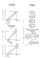
- a point S indicates a picking starting position
- a point E indicates an arriving position.
- a picking time namely, a standard checking pin retracting time TS
- a standard arrival time TE namely, a standard time of arrival of the free end of the picked weft yarn 2 at the arrival position E is determined accordingly.
- the distance of travel of the weft yarn 2 as a function of time t is expressed by a straight line as shown in Fig. 3, in which the gradient of the straight line corresponds to the fixed running speed of the picked weft yarn 2.
- Time ⁇ T in Fig. 3 is a range of adjustment of the actual checking pin retracting time ts according to the actual running speed between a maximum running speed and a minimum running speed.
- the standard arrival time TE and the standard checking pin retracting time TS are given by means of the data setting devices 21 and 22 to the memory device 19, and a temporary checking pin retracting time TS0 for the initial period of the picking operation after the supply yarn package has been changed from the yarn package 3a to the yarn package 3b is set by means of the initial data setting device 17.
- the detector 13 disposed at the arrival side detects the arrival of the free end of the picked weft yarn 2 at the arrival position E and gives a detection signal to the arithmetic unit 24 while the encoder 25 sends phase angle signals respectively representing momentary phase angles of the main shaft of the loom. Then, the arithmetic unit 24 reduces the detection signal into a corresponding phase angle of the main shaft of the loom.
- the arithmetic unit 24 calculates the moving average of the actual arrival times te every successive several picking cycles and gives the moving average to the comparator 23. Then, the comparator 23 compares the moving average of the measured arrival times te and the standard arrival time TE stored in the memory device 19.
- (standard arrival time TE) (moving average of the measured arrival times te) as indicated by a continuous line in Fig. 3, the picking operation is normal, and hence any particular correcting operation is unnecessary.
- the actual arrival time te is corrected automatically and continuously to adjust the actual arrival time gradually to a target arrival time, i.e., the standard arrival time TE. Consequently, the free end of the picked weft yarn 2 arrives at the arrival position E at the standard arrival time TE.
- the actual checking pin retracting time ts varies over and below the standard checking pin retracting time TS.
- the earlier limit time of the time range ⁇ T corresponds to a preliminary jetting starting time when the picking nozzle 10 starts preliminary jetting.
- the use of the picking controller 15 is not limited to the control of the checking pin 7, but the picking controller 15 can be used also for the continuous regulation of the jetting starting timing of the picking nozzle 10 in relation to or without relation to the timing of the preliminary jetting.
- the supply yarn package change detector 14 Upon the detection of the supply yarn package, the supply yarn package change detector 14 gives a detection signal to the delay circuit 16. Then, the delay circuit 16 gives a reset signal to the initial data setting device 17 and the arithmetic unit 24 after a predetermined time, a predetermined number of picking cycles or a predetermined angle of rotation of the main shaft of the loom from the reception of the detection signal from the supply yarn package change detector 14.
- the initial data setting device 17 gives a checking pin retracting time TS0 for a supply yarn package change mode to the data updating device 18, and the checking pin retracting time TS0 is stored preferentially in the memory device 19.
- the arithmetic unit 24 erases the previously stored checking pin retracting time TS ⁇ t.
- the weft yarn 2 supplied from the yarn package 3b which has replaced the yarn package 3a is picked at the checking pin retracting time TS0 from the first picking cycle for picking the weft yarn 2 supplied from the yarn package 3b.
- the picking controller 15 detects the actual arrival times te in the manner as stated above, and updates the stored data to provide a new checking pin retracting time TS ⁇ t.
- the predetermined delay defined by time or by the number of picking cycles before setting the new checking pin retracting time corresponds to a time between the change of the supply yarn package from the yarn package 3a to the yarn package 3b and the start of picking the weft yarn 2 supplied from the new yarn package 3b.
- the delay before the first picking cycle for a new supply yarn package after the supply yarn package has been changed must be determined properly for each picking device taking into consideration the period of picking operation of each picking device.
- the picking controller is adapted for controlling the jetting starting timing of the picking nozzle 10 as well as the checking pin retracting timing, both the jetting starting timing and the checking pin retracting timing must be changed simultaneously when the supply yarn package is changed.
- the actual arrival time te is detected directly at the arrival position, however, the arrival time can be detected indirectly through the detection of a time when the weft yarn 2 is unwound from the drum 6 by a specific number of loops necessary for one picking cycle. Accordingly, the arrival time may be detected on the picking side of the loom.
Landscapes
- Engineering & Computer Science (AREA)
- Textile Engineering (AREA)
- Looms (AREA)
Applications Claiming Priority (2)
| Application Number | Priority Date | Filing Date | Title |
|---|---|---|---|
| JP61189116A JPS6342940A (ja) | 1986-08-11 | 1986-08-11 | よこ入れ制御装置 |
| JP189116/86 | 1986-08-11 |
Publications (3)
| Publication Number | Publication Date |
|---|---|
| EP0256487A2 true EP0256487A2 (de) | 1988-02-24 |
| EP0256487A3 EP0256487A3 (en) | 1990-08-22 |
| EP0256487B1 EP0256487B1 (de) | 1994-06-01 |
Family
ID=16235651
Family Applications (1)
| Application Number | Title | Priority Date | Filing Date |
|---|---|---|---|
| EP87111592A Expired - Lifetime EP0256487B1 (de) | 1986-08-11 | 1987-08-11 | Verfahren und Vorrichtung zum Kontrollieren des Schusseintrags |
Country Status (5)
| Country | Link |
|---|---|
| US (1) | US4815502A (de) |
| EP (1) | EP0256487B1 (de) |
| JP (1) | JPS6342940A (de) |
| KR (1) | KR900002062B1 (de) |
| DE (1) | DE3789925T2 (de) |
Cited By (3)
| Publication number | Priority date | Publication date | Assignee | Title |
|---|---|---|---|---|
| EP0454199A1 (de) * | 1990-04-27 | 1991-10-30 | Picanol N.V. | Verfahren und Vorrichtung zum Liefern von Schussgarn an das Webfach einer Webmaschine |
| WO1993017948A1 (de) * | 1992-03-06 | 1993-09-16 | Maschinenfabrik Rieter Ag | Verfahren und vorrichtung zum überwachen von bewegungsabläufen an spulmaschinen |
| US5676323A (en) * | 1992-03-06 | 1997-10-14 | Maschinenfabrik Rieter Ag | Apparatus and method for changing and winding bobbins involving the correction of movement sequences in a moving element |
Families Citing this family (10)
| Publication number | Priority date | Publication date | Assignee | Title |
|---|---|---|---|---|
| BE1001919A3 (nl) * | 1988-12-05 | 1990-04-10 | Picanol Nv | Luchtweefmachine, met een verbeterde voeding voor de inslagdraden. |
| US6273221B1 (en) * | 1998-11-06 | 2001-08-14 | Nexen Group, Inc. | Servo-motor brake |
| WO2002033157A2 (de) * | 2000-10-18 | 2002-04-25 | Iropa Ag | Verfahren zum eintragen von schussfäden und fadenliefervorrichtung |
| KR102083945B1 (ko) | 2015-11-24 | 2020-03-03 | 주식회사 엘지화학 | 열가소성 수지, 이의 제조방법 및 이를 포함하는 열가소성 수지 조성물 |
| KR101931585B1 (ko) | 2016-03-18 | 2019-02-26 | 주식회사 엘지화학 | 열가소성 수지 조성물 및 이로부터 제조된 성형품 |
| CN105937084B (zh) * | 2016-06-23 | 2017-12-08 | 苏州汇川技术有限公司 | 储纬器退纱控制系统及方法 |
| US11434358B2 (en) | 2018-05-14 | 2022-09-06 | Lg Chem, Ltd. | Matrix copolymer, graft copolymer, and thermoplastic resin composition |
| JP7260387B2 (ja) * | 2019-05-06 | 2023-04-18 | 津田駒工業株式会社 | 水噴射式織機における緯入れ方法及び装置 |
| CN119654375A (zh) | 2022-10-21 | 2025-03-18 | 株式会社Lg化学 | 树脂组合物 |
| KR20250137826A (ko) | 2024-03-12 | 2025-09-19 | 주식회사 엘지화학 | 수지 조성물 |
Citations (3)
| Publication number | Priority date | Publication date | Assignee | Title |
|---|---|---|---|---|
| JPS5818446A (ja) | 1981-07-02 | 1983-02-03 | リユ−テイテ・シユトラ−ケ・ビ−ブイ | 横糸移送用流体吹出しノズルを備えた織機を用いる織物の織成方法及び横糸移送用流体吹出しノズルを備えた織機 |
| JPS60136379U (ja) | 1984-02-17 | 1985-09-10 | 津田駒工業株式会社 | よこ入れ制御装置 |
| JPS6182973U (de) | 1984-11-07 | 1986-06-02 |
Family Cites Families (9)
| Publication number | Priority date | Publication date | Assignee | Title |
|---|---|---|---|---|
| CH643013A5 (en) * | 1980-04-01 | 1984-05-15 | Sulzer Ag | Weft-thread storage device for weaving machines |
| US4627474A (en) * | 1982-09-03 | 1986-12-09 | Aktiebolaget Iro | Yarn storing, feeding and measuring device |
| JPS5995179U (ja) * | 1982-12-14 | 1984-06-28 | 津田駒工業株式会社 | エアジェットルーム用緯入れ速度自動制御装置 |
| JPS59125944A (ja) * | 1982-12-27 | 1984-07-20 | 日産自動車株式会社 | 断片織機の緯糸供給装置 |
| BE899671A (nl) * | 1984-05-16 | 1984-11-16 | Picanol Nv | Regelbare sturing van de inslagdraad van een weefgetouw. |
| JPS60259652A (ja) * | 1984-06-06 | 1985-12-21 | 津田駒工業株式会社 | よこ糸貯留装置の係止ピン制御方法およびその装置 |
| JPH0733614B2 (ja) * | 1985-04-05 | 1995-04-12 | 津田駒工業株式会社 | よこ入れ制御方法およびその装置 |
| JPS62117853A (ja) * | 1985-11-15 | 1987-05-29 | 津田駒工業株式会社 | よこ入れ制御方法およびその装置 |
| JPH075222B2 (ja) * | 1985-12-28 | 1995-01-25 | 津田駒工業株式会社 | ドラム式緯糸貯留装置の係止ピン制御装置 |
-
1986
- 1986-08-11 JP JP61189116A patent/JPS6342940A/ja active Pending
-
1987
- 1987-07-31 KR KR1019870008376A patent/KR900002062B1/ko not_active Expired
- 1987-08-10 US US07/083,585 patent/US4815502A/en not_active Expired - Lifetime
- 1987-08-11 EP EP87111592A patent/EP0256487B1/de not_active Expired - Lifetime
- 1987-08-11 DE DE3789925T patent/DE3789925T2/de not_active Expired - Fee Related
Patent Citations (3)
| Publication number | Priority date | Publication date | Assignee | Title |
|---|---|---|---|---|
| JPS5818446A (ja) | 1981-07-02 | 1983-02-03 | リユ−テイテ・シユトラ−ケ・ビ−ブイ | 横糸移送用流体吹出しノズルを備えた織機を用いる織物の織成方法及び横糸移送用流体吹出しノズルを備えた織機 |
| JPS60136379U (ja) | 1984-02-17 | 1985-09-10 | 津田駒工業株式会社 | よこ入れ制御装置 |
| JPS6182973U (de) | 1984-11-07 | 1986-06-02 |
Cited By (4)
| Publication number | Priority date | Publication date | Assignee | Title |
|---|---|---|---|---|
| EP0454199A1 (de) * | 1990-04-27 | 1991-10-30 | Picanol N.V. | Verfahren und Vorrichtung zum Liefern von Schussgarn an das Webfach einer Webmaschine |
| BE1004150A3 (nl) * | 1990-04-27 | 1992-09-29 | Picanol Nv | Werkwijze en inrichting voor het toevoeren van inslaggaren aan de gaap bij een weefmachine. |
| WO1993017948A1 (de) * | 1992-03-06 | 1993-09-16 | Maschinenfabrik Rieter Ag | Verfahren und vorrichtung zum überwachen von bewegungsabläufen an spulmaschinen |
| US5676323A (en) * | 1992-03-06 | 1997-10-14 | Maschinenfabrik Rieter Ag | Apparatus and method for changing and winding bobbins involving the correction of movement sequences in a moving element |
Also Published As
| Publication number | Publication date |
|---|---|
| KR880003046A (ko) | 1988-05-13 |
| US4815502A (en) | 1989-03-28 |
| KR900002062B1 (ko) | 1990-03-31 |
| JPS6342940A (ja) | 1988-02-24 |
| EP0256487B1 (de) | 1994-06-01 |
| DE3789925D1 (de) | 1994-07-07 |
| EP0256487A3 (en) | 1990-08-22 |
| DE3789925T2 (de) | 1994-09-08 |
Similar Documents
| Publication | Publication Date | Title |
|---|---|---|
| EP0222410B1 (de) | Verfahren und Vorrichtung für die Schusseintragkontrolle | |
| EP0256487B1 (de) | Verfahren und Vorrichtung zum Kontrollieren des Schusseintrags | |
| US4827990A (en) | Automatic picking regulating method for air jet loom and apparatus for carrying out the same | |
| EP0276829B1 (de) | Schusskontrollvorrichtung für Düsenwebmaschine | |
| EP0234064B1 (de) | Verfahren und Vorrichtung zum automatischen Überwachen des Schussfadeneintrags | |
| EP0196676B1 (de) | Verfahren und Vorrichtung für die Schussfadeneintragkontrolle | |
| US4967806A (en) | Automatic weft picking control system for fluid jet loom | |
| EP3867431B1 (de) | Fadenzuführvorrichtung mit lernverfahren | |
| EP0477877B1 (de) | Positive Schussfadenzuführvorrichtung für Düsenwebmaschine | |
| US4886094A (en) | Picking controller for a fluid jet loom | |
| JPH041099B2 (de) | ||
| EP1259667B1 (de) | Kontrollverfahren für eine webvorrichtung und webvorrichtung zur durchführung dieses verfahrens | |
| EP0314056B1 (de) | Verfahren zum Abmessen der Fadenlänge bei einer Schusseintragsvorrichtung | |
| JPH0465Y2 (de) | ||
| JPH0332542Y2 (de) | ||
| JPH0713339B2 (ja) | よこ入れ装置の到達タイミング自動調節装置 | |
| JPH0380897B2 (de) | ||
| JP2775483B2 (ja) | ジェットルームの緯入れ制御装置 | |
| JPH0713341B2 (ja) | よこ入れ制御装置 | |
| WO1993023595A1 (en) | A device for controlling the yarn course between a stationary yarn package and a periodically operating yarn consuming device | |
| KR19980024837A (ko) | 직기에서의 위사제어장치 | |
| JPH0762292B2 (ja) | よこ糸測長貯留装置の係止ピンタイミング設定方法およびその装置 | |
| JPH0441744A (ja) | 空気噴射式織機の緯入れ制御装置 | |
| JPS6134251A (ja) | 流体噴射式織機の制御装置 | |
| JPH0253936A (ja) | 流体噴射式織機のよこ入れ装置 |
Legal Events
| Date | Code | Title | Description |
|---|---|---|---|
| PUAI | Public reference made under article 153(3) epc to a published international application that has entered the european phase |
Free format text: ORIGINAL CODE: 0009012 |
|
| AK | Designated contracting states |
Kind code of ref document: A2 Designated state(s): CH DE FR GB IT LI |
|
| PUAL | Search report despatched |
Free format text: ORIGINAL CODE: 0009013 |
|
| AK | Designated contracting states |
Kind code of ref document: A3 Designated state(s): CH DE FR GB IT LI |
|
| 17P | Request for examination filed |
Effective date: 19910123 |
|
| 17Q | First examination report despatched |
Effective date: 19920522 |
|
| GRAA | (expected) grant |
Free format text: ORIGINAL CODE: 0009210 |
|
| AK | Designated contracting states |
Kind code of ref document: B1 Designated state(s): CH DE FR GB IT LI |
|
| REF | Corresponds to: |
Ref document number: 3789925 Country of ref document: DE Date of ref document: 19940707 |
|
| ITF | It: translation for a ep patent filed | ||
| ET | Fr: translation filed | ||
| PLBI | Opposition filed |
Free format text: ORIGINAL CODE: 0009260 |
|
| 26 | Opposition filed |
Opponent name: LINDAUER DORNIER GESELLSCHAFT MBH Effective date: 19950209 |
|
| PLBL | Opposition procedure terminated |
Free format text: ORIGINAL CODE: EPIDOS OPPC |
|
| PGFP | Annual fee paid to national office [announced via postgrant information from national office to epo] |
Ref country code: GB Payment date: 19960802 Year of fee payment: 10 |
|
| PGFP | Annual fee paid to national office [announced via postgrant information from national office to epo] |
Ref country code: FR Payment date: 19960809 Year of fee payment: 10 |
|
| PGFP | Annual fee paid to national office [announced via postgrant information from national office to epo] |
Ref country code: CH Payment date: 19960821 Year of fee payment: 10 |
|
| PLBL | Opposition procedure terminated |
Free format text: ORIGINAL CODE: EPIDOS OPPC |
|
| PLBM | Termination of opposition procedure: date of legal effect published |
Free format text: ORIGINAL CODE: 0009276 |
|
| STAA | Information on the status of an ep patent application or granted ep patent |
Free format text: STATUS: OPPOSITION PROCEDURE CLOSED |
|
| 27C | Opposition proceedings terminated |
Effective date: 19960802 |
|
| PG25 | Lapsed in a contracting state [announced via postgrant information from national office to epo] |
Ref country code: GB Free format text: LAPSE BECAUSE OF NON-PAYMENT OF DUE FEES Effective date: 19970811 |
|
| PG25 | Lapsed in a contracting state [announced via postgrant information from national office to epo] |
Ref country code: LI Free format text: LAPSE BECAUSE OF NON-PAYMENT OF DUE FEES Effective date: 19970831 Ref country code: CH Free format text: LAPSE BECAUSE OF NON-PAYMENT OF DUE FEES Effective date: 19970831 |
|
| GBPC | Gb: european patent ceased through non-payment of renewal fee |
Effective date: 19970811 |
|
| REG | Reference to a national code |
Ref country code: CH Ref legal event code: PL |
|
| PG25 | Lapsed in a contracting state [announced via postgrant information from national office to epo] |
Ref country code: FR Free format text: LAPSE BECAUSE OF NON-PAYMENT OF DUE FEES Effective date: 19980430 |
|
| REG | Reference to a national code |
Ref country code: FR Ref legal event code: ST |
|
| PGFP | Annual fee paid to national office [announced via postgrant information from national office to epo] |
Ref country code: DE Payment date: 20020816 Year of fee payment: 16 |
|
| PG25 | Lapsed in a contracting state [announced via postgrant information from national office to epo] |
Ref country code: DE Free format text: LAPSE BECAUSE OF NON-PAYMENT OF DUE FEES Effective date: 20040302 |
|
| PG25 | Lapsed in a contracting state [announced via postgrant information from national office to epo] |
Ref country code: IT Free format text: LAPSE BECAUSE OF NON-PAYMENT OF DUE FEES Effective date: 20050811 |