EP0256529A1 - Méthode pour empêcher la désactivation d'un catalyseur de dénitration - Google Patents
Méthode pour empêcher la désactivation d'un catalyseur de dénitration Download PDFInfo
- Publication number
- EP0256529A1 EP0256529A1 EP87111769A EP87111769A EP0256529A1 EP 0256529 A1 EP0256529 A1 EP 0256529A1 EP 87111769 A EP87111769 A EP 87111769A EP 87111769 A EP87111769 A EP 87111769A EP 0256529 A1 EP0256529 A1 EP 0256529A1
- Authority
- EP
- European Patent Office
- Prior art keywords
- ppm
- catalyst
- amount
- fuel
- coal
- Prior art date
- Legal status (The legal status is an assumption and is not a legal conclusion. Google has not performed a legal analysis and makes no representation as to the accuracy of the status listed.)
- Granted
Links
Images


Classifications
-
- B—PERFORMING OPERATIONS; TRANSPORTING
- B01—PHYSICAL OR CHEMICAL PROCESSES OR APPARATUS IN GENERAL
- B01J—CHEMICAL OR PHYSICAL PROCESSES, e.g. CATALYSIS OR COLLOID CHEMISTRY; THEIR RELEVANT APPARATUS
- B01J23/00—Catalysts comprising metals or metal oxides or hydroxides, not provided for in group B01J21/00
- B01J23/90—Regeneration or reactivation
- B01J23/94—Regeneration or reactivation of catalysts comprising metals, oxides or hydroxides of the iron group metals or copper
-
- B—PERFORMING OPERATIONS; TRANSPORTING
- B01—PHYSICAL OR CHEMICAL PROCESSES OR APPARATUS IN GENERAL
- B01D—SEPARATION
- B01D53/00—Separation of gases or vapours; Recovering vapours of volatile solvents from gases; Chemical or biological purification of waste gases, e.g. engine exhaust gases, smoke, fumes, flue gases, aerosols
- B01D53/34—Chemical or biological purification of waste gases
- B01D53/74—General processes for purification of waste gases; Apparatus or devices specially adapted therefor
- B01D53/86—Catalytic processes
-
- B—PERFORMING OPERATIONS; TRANSPORTING
- B01—PHYSICAL OR CHEMICAL PROCESSES OR APPARATUS IN GENERAL
- B01D—SEPARATION
- B01D53/00—Separation of gases or vapours; Recovering vapours of volatile solvents from gases; Chemical or biological purification of waste gases, e.g. engine exhaust gases, smoke, fumes, flue gases, aerosols
- B01D53/34—Chemical or biological purification of waste gases
- B01D53/74—General processes for purification of waste gases; Apparatus or devices specially adapted therefor
- B01D53/86—Catalytic processes
- B01D53/8621—Removing nitrogen compounds
- B01D53/8625—Nitrogen oxides
-
- B—PERFORMING OPERATIONS; TRANSPORTING
- B01—PHYSICAL OR CHEMICAL PROCESSES OR APPARATUS IN GENERAL
- B01D—SEPARATION
- B01D53/00—Separation of gases or vapours; Recovering vapours of volatile solvents from gases; Chemical or biological purification of waste gases, e.g. engine exhaust gases, smoke, fumes, flue gases, aerosols
- B01D53/34—Chemical or biological purification of waste gases
- B01D53/74—General processes for purification of waste gases; Apparatus or devices specially adapted therefor
- B01D53/86—Catalytic processes
- B01D53/8621—Removing nitrogen compounds
- B01D53/8625—Nitrogen oxides
- B01D53/8628—Processes characterised by a specific catalyst
-
- B—PERFORMING OPERATIONS; TRANSPORTING
- B01—PHYSICAL OR CHEMICAL PROCESSES OR APPARATUS IN GENERAL
- B01J—CHEMICAL OR PHYSICAL PROCESSES, e.g. CATALYSIS OR COLLOID CHEMISTRY; THEIR RELEVANT APPARATUS
- B01J23/00—Catalysts comprising metals or metal oxides or hydroxides, not provided for in group B01J21/00
- B01J23/70—Catalysts comprising metals or metal oxides or hydroxides, not provided for in group B01J21/00 of the iron group metals or copper
- B01J23/74—Iron group metals
- B01J23/745—Iron
-
- B—PERFORMING OPERATIONS; TRANSPORTING
- B01—PHYSICAL OR CHEMICAL PROCESSES OR APPARATUS IN GENERAL
- B01J—CHEMICAL OR PHYSICAL PROCESSES, e.g. CATALYSIS OR COLLOID CHEMISTRY; THEIR RELEVANT APPARATUS
- B01J23/00—Catalysts comprising metals or metal oxides or hydroxides, not provided for in group B01J21/00
- B01J23/90—Regeneration or reactivation
-
- B—PERFORMING OPERATIONS; TRANSPORTING
- B01—PHYSICAL OR CHEMICAL PROCESSES OR APPARATUS IN GENERAL
- B01J—CHEMICAL OR PHYSICAL PROCESSES, e.g. CATALYSIS OR COLLOID CHEMISTRY; THEIR RELEVANT APPARATUS
- B01J38/00—Regeneration or reactivation of catalysts, in general
- B01J38/48—Liquid treating or treating in liquid phase, e.g. dissolved or suspended
Definitions
- the present invention relates to a method of controlling the deactivation of a denitrating catalyst resulting from an exhaust gas dust in a boiler, a furnace or the like which employs a fossil fuel such as heavy oil, pulverized coal, COM, CWM, etc.
- Examples of measures designed to reduce the generation of nitrogen oxides NOx from fossil fuels include: (1) improvements in burning techniques, for example, low oxygen combustion, two-stage combustion, exhaust gas recirculation combustion, and low NOx burner, (2) selection of fuel types (selection of fuels having a low content of N matter); and (3) development of exhaust gas denitration techniques. Among these measures, (3) is considered to be the most practical approach.
- Examples of exhaust gas denitration techniques include: the catalytic reduction method in which NOx is reduced into N2 at 300°C to 400°C by means of a reducing gas such as ammonia in the presence of a catalyst; the catalytic decomposition method in which NOx is decomposed at 700°C to 800°C in the presence of a catalyst, and the absorption method in which NOx is absorbed into active carbon.
- a reducing gas such as ammonia in the presence of a catalyst
- the catalytic decomposition method in which NOx is decomposed at 700°C to 800°C in the presence of a catalyst
- the absorption method in which NOx is absorbed into active carbon.
- the catalytic reduction method which consists of a relatively simple process and utilizes ammonia is widely used and is regarded as being the most reliable. This invention relates to this dry ammonia catalytic reduction method.
- the principle of this method is the NOx is reduced into N2 and H2O generally by adding NH3 to the exhaust gas (300°C to 400°C) from a boiler outlet and then by passing the resultant mixture through a catalyst layer (for example, V2O2, Fe2O3, WO3, etc.) in a reaction vessel.
- a catalyst layer for example, V2O2, Fe2O3, WO3, etc.
- This process is simple and suitable for treating a large volume of exhaust gas.
- the reaction formulae of this process are shown as follows: 4NO + 4NH3 + O2 -- ⁇ N2 + 6H2O 2NO2 + 4NH3 + O2 -- ⁇ 3N2 + 6H2O
- Another method is the non-catalytic reduction method which consists of injecting ammonia into a high temperature area of about 800°C to 1100°C and effecting denitration in the absence of a catalyst.
- this method is hardly even used.
- This invention relates to the above-mentioned dry ammonia catalytic reduction method.
- the most serious problem of this method is deactivation of the catalyst employed, which causes a reduced denitration efficiency and thus leads to the need for an increased amount of ammonia to be added.
- increasing the amount of ammonia added leads to an increased amount of unreacted ammonia passing through the denitrizer, and this unreacted ammonia reacts with the SO2 and SO3 present in a gas to produce NH4HSO4 which has a low melting point of 147°C.
- Adhesion of this low-melting point substance to the elements of a downstream air heater (AH) causes clogging of the elements and a rising draft, which may in turn result in an unexpected shut-down. In order to prevent such a problem, inspection and repair of the catalyst becomes very important.
- the catalyst is water-washed to remove any adhering matter after a boiler shut-down. If the catalyst function can be restored without stopping the boiler operation, great financial advantage will be obtained. Under these circumstances, a method of adding an iron compound powder just before and after the position of a denitrizer by using a sootblower is employed.
- the iron compounds added include Fe2O3, Fe3O4, Fe(OH)2, Fe(OH)3, FeCO3, FeOOH, etc.
- an iron compound powder is added to a gas atmosphere with a temperature of 600°C or higher, a large amount of iron compound may be deposited on the heating surfaces of various devices which are disposed on the downstream side, such as a superheater (SH), a re-heater (RH), a feedwater heater or economizer (ECO), etc., resulting undesirably in a rise in the exhaust gas temperature and an increase in the draft in the furnace.
- SH superheater
- RH re-heater
- ECO feedwater heater or economizer
- iron compounds are inexpensive, they are readily poisoned and deactivated by SOx, and therefore employment of an iron compound along limits any possible extension of the life of the catalyst. For this reason, methods have heretofore been proposed wherein an oxide of a heavy metal such as Ti, V, W or the like is employed as an active ingredient as well as an iron compound and is injected into the denitrizer using an ammonia injection nozzle or the like. These oxides of heavy metals are added in the form of an aqueous solution of an ammonia compound.
- a heavy metal such as Ti, V, W or the like
- vanadium compounds acts as a strong oxidizing catalyst, have a low melting point and produce low-melting compounds such as n ⁇ Na2O ⁇ mV2O5 to corrode tubes in boilers and the like, and therefore they have been excluded from the group of substances which may be employed as additives for the above-described purposes.
- tungsten oxides are known as oxidizing catalysts having a high melting point which act so as to cover the low-melting property of vanadium.
- these compounds have not been positively added to fuel.
- SOx such as vanadium and tungsten compounds
- deactivation of a denitrating catalyst can be effectively prevented by adding to a mill installed in a fuel line or at a point upstream of the mill an iron compound having an extremely small particle diameter in an amount in the range of 5 to 2000 ppm relative to the amount of fuel, by further pulverizing the added iron compound together with coal agglomerates in the mill to ensure even and strong adhesion of the iron compound to the surface of coal particles, by conducting the iron compound into an exhaust gas dust together with alkali metal oxides such as Na2O, K2O, etc., alkaline earth metal oxides such as CaO, MgO, BaO, etc., or unburnt carbon, and then by ensuring adhesion of the iron compound to a catalyst layer in a denitrating reactor.
- alkali metal oxides such as Na2O, K2O, etc.
- alkaline earth metal oxides such as CaO, MgO, BaO, etc.
- Fe2O3 or Fe3O4 is produced as an oxidizing catalyst on the surface of fly ash.
- Coal usually contains 2 to 20% by weight of iron compounds, most of which are present as FeS2, FeCO3 or the like. These compounds lie buried in the coal particles and stay in them after burning, so that most of these compounds may not show adsorptive action toward NOx as catalysts.
- catalyst poisoning substances in coal such as CaO, Na2O, sulfur-containing matter, and the like fall as clinker to the bottom of a furnace to some extent, resulting in an extension of the life of the catalyst.
- Water-soluble iron salts such as ferrous sulfate, iron acetate, iron chlorides (FeCl3, FeCl4), iron hydroxides (Fe(OH)2, Fe(OH)3) and the like and aqueous solutions thereof are effective as iron compounds for this invention.
- Powders such as Fe2O3, Fe3O4, FeO, FeOOH, Fe(OH)3, Fe(OH)2 and the like and water slurries thereof are also effective as iron compounds provided that their particle diameter is smaller than 100 mesh pass. It is a matter of course that the smaller the particle diameter, the higher, the activity and the smaller the amount added.
- At least one compound selected from the following three different kinds of compound that is, iron compounds in an amount of 5 to 200 ppm (in terms of Fe2O3), vanadium compounds in an amount of 3 to 50 ppm (in terms of V2O5), and tungsten compounds in an amount of 1 to 15 ppm (in terms of WO3).
- iron compounds in an amount of 5 to 200 ppm
- vanadium compounds in an amount of 3 to 50 ppm
- tungsten compounds in an amount of 1 to 15 ppm in terms of WO3
- water-soluble ferrous salts such as organic acid ferrous salt, ferrous sulfate, ferrous acetate, ferrous chloride and iron hydroxide, or an aqueous solution, a water slurry and an oil slurry of these ferrous salts
- Fe2O3, Fe3O4, FeO, FeO ⁇ OH, Fe(OH)3 and Fe(OH)2 in the form of powder, a water slurry or an oil slurry.
- vanadium compounds examples include water-soluble vanadium compounds such as organic acid vanadium salt, ammonium metavanadate (NH4VO3), vanadium sulfate (VOSO4), sodium vanadates (NaVO3, Na3VO4), or an aqueous solution of these compounds, and vanadium pentaoxide (V2O5), ferrous vanadate or the like in the form of powder and a water slurry.
- water-soluble vanadium compounds such as organic acid vanadium salt, ammonium metavanadate (NH4VO3), vanadium sulfate (VOSO4), sodium vanadates (NaVO3, Na3VO4), or an aqueous solution of these compounds, and vanadium pentaoxide (V2O5), ferrous vanadate or the like in the form of powder and a water slurry.
- NH4VO3 ammonium metavanadate
- VOSO4 vanadium sulfate
- NaVO3, Na3VO4 sodium
- tungsten compounds include water-soluble tungstates such as organic acid tungsten salt, ammonium tungstate [(NH4)2W4O18] and sodium tungstate (Na2WO4), or anaqueous solution of these tungstates, and tungsten oxides (WO3, WO2), tungsten carbide (WC), iron tungstate [Fe(WO4)3] or the like in the form of powder or a water slurry. It is a matter of course that as the particle diameter of these compounds decreases, the activity becomes stronger, and the amount of compound that needs to be added decreases.
- water-soluble tungstates such as organic acid tungsten salt, ammonium tungstate [(NH4)2W4O18] and sodium tungstate (Na2WO4), or anaqueous solution of these tungstates, and tungsten oxides (WO3, WO2), tungsten carbide (WC), iron tungstate [Fe(WO4)3] or the like in the form of powder or a water slurry
- the average particle diameter is preferably selected so as to be 5 ⁇ m or less.
- An average particle diameter in excess of 5 ⁇ m requires that a large amount of powder be added. As a result, an excessive amount of powder may adhere to the heating surfaces to lower the heat absorbing capacity, and this leads to a rise in the exhaust gas temperature, resulting in economic losses or trouble.
- the average particle diameter is preferably selected to be 2 to 3 ⁇ m or less.
- An average particle diameter in excess of 2 to 3 ⁇ m deteriorates the stability of the product, so that, even if an excellent surface active agent is used, particles are, undesirably, readily precipitated.
- a catalyst which is formed by coating an iron oxide, a vanadium oxide and a tungsten oxide onto a TiO2 carrier is employed. Since the present invention enables a fresh active catalyst to be supplied at all times, the life of the denitrating catalyst can be extended irrespective of its composition.
- the carrier of the catalyst is not necessarily limited to TiO2 and other substances may also be employed such as Al2O3 provided that the substance employed is not harmful.
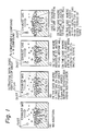
- Figs. 1(A), 1(B), 1(C) and 1(D) show the way in which an additive adheres to a denitrating catalyst in comparison with the case where no additive is employed.
- dust particles attached to the catalyst may reduce the surface area of the catalyst and therefore lower the activity.
- Fig. 1(B) shows ultrafine iron oxide particles (about 0.1 ⁇ m) blown off together with steam ahead of the position of the denitrizer by the use of a sootblower. Because of this sootblowing, the proportion of small iron oxide particles being discharged to the outside may be much larger than the amount of particles adhering to the catalyst, which is uneconomical. In addition, ultrafine iron oxide particles are very costly.
- Fig. 1(C) shows the case where an additive is added to fuel before the position of a mill and the catalyst is in its fresh state. Since dust particles which have small iron particles attached to their surfaces may adhere to the surface of the catalyst, there is no fear of the surface area of the catalyst being reduced, and since an iron compound, a vanadium compound and a tungsten compound which are active are supplied at all times, lowering of the activity of the catalyst is prevented and the activity is improved instead.
- Fig. 1(D) shows the case where an additive is added to fuel after the catalyst has been used for a given period of time.
- Iron, vanadium and tungsten compound particles (mainly in the form of oxides) which are attached to dust particles may adhere to the dust particles which have already been attached to the surface of the catalyst before the additive was used, thus preventing lowering of the activity.
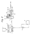
- reference numeral 1 denotes a bunker for temporarily storing coal
- 2 is a coal feeder which weighs the coal delivered from the bunker and feeds a fixed amount of coal
- 3 is a mill which pulverizes the coal to a particle size of less than 100 mesh preferably less than 200 mesh
- 4 is a blower which uses air to convey the pulverized coal toward a burner
- 6 is a storage tank containing an additive
- 5 is a pump which injects the additive. This is a constant delivery pump which is capable of feeding a fixed amount of additive for a given amount of fuel.
- the injection point is located at an inlet of the mill 3, where the additive is blended with the pulverized coal.
- the mill inlet is the most suitable point for injection because the iron compound is strongly pressed against the surface of coal particles by a roller in the mill. This leads to an increase in the oxidizing catalytic function of the iron carried on carbon.
- it is effective to add an equal amount of additive at a point upstream of each mill.
- Reference numeral 8 is a boiler
- 9 is a superheater (SH) which superheats vapor
- 10 is an economizer (ECO) which heats feedwater
- 11 is an ammonia-injecting line for denitrating
- 12 is an injection nozzle
- 13 is an exhaust gas duct
- 14 is a reaction vessel in which the reaction between ammonia and NOx takes place.
- NOx is reduced on a catalytic layer that is present in the reaction vessel into N2 and H2O.
- the amount of ammonia to be injected is measured at the inlet and outlet of the reaction vessel 14, and is automatically controlled so as not to give a lower rate than a predetermined denitration rate. Consequently, when the catalyst is deactivated to result in a lowered denitration rate, the amount of ammonia to be injected is increased.
- Reference numeral 15 denotes an air heater which heats air utilizing the heat of an exhaust gas. Once the exhaust gas has left the air heater it is discharged from a stack to the atmosphere via an electrostatic precipitator, a desulfurizer, and so forth.
- an additive which is in the form of an oil slurry or an oil-soluble organic acid salt is supplied to the high-pressure area immediately before the position of the burner by means of a constant delivery pump.
- the arrangement of the other section is the same as that in the case of a coal combustion boiler.
- the denitrating catalyst used was prepared by coating a mixture consisting of 30% vanadium oxide, 55% iron oxide, and 15% tungsten oxide onto a TiO2 carrier.
- the burning conditions of the boiler and the fuel properties were as follows:
- Table 1 shows the results obtained by charging an aqueous solution of ferrous sulfate into a mill installed in a coal fuel line according to the method of the present invention.
- the load of the boiler and the O2 ratio at the ECO outlet were set to 175 MW and 4%, respectively.
- the amount of ammonia injected decreased from 61 kg/H to 45 kg/H corresponding to the reduction in NOx, showing that the amount of NOx was definitely reduced at the outlet of the denitrizer.
- the exhaust gas temperature at the ECO outlet was 350°C with the addition amount of 50 ppm, which is the same temperature as in the case where no additive was used. However, when the amount added was 2000 ppm, the temperature increased to 355°C, showing a 5°C rise in temperature. Any further addition had almost no effect on the reduction of NOx.
- the unreacted ammonia reacts with SO3 present in the gas to produce ammonium hydrogen sulfate NH4HSO4 which adheres to such apparatus as air heaters and causes clogging.
- an aqueous solution of ferrous sulfate is very effective because of its extremely small particle diameter of 50 ⁇ .
- a water slurry and powder are also effective, and the smaller the particle size, the greater the effect.
- Table 2 shows the results obtained by pulverizing to 100 mesh pass a water slurry consisting of ferrosoferric oxide (10% by weight in terms of Fe2O3) and 5% by weight of a surface active agent (for example, an anionic and then by charging the pulverized water slurry at a point upstream of the mill installed in a coal fuel line.
- the load of the boiler and the ratio of O2 at the ECO outlet were set to 175 MW and 4%, respectively.
- Water slurries of Fe3O4 were prepared by adding 5 ppm, 50 ppm and 2000 ppm in terms of Fe2O3 to the fuel.
- Table 3 shows the results obtained by charging a powder (100 mesh-pass) of ferrosoferric oxide (magnetite) at a point upstream of the mill installed in a coal fuel line.
- the load of the boiler and the ratio of O2 at the ECO outlet were set to 175 MW and 4%, respectively.
- the respective amounts of additive were predetermined at 5 ppm, 50 ppm and 2000 ppm.
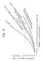
- Fig. 3 which shows the amount of un-reacted ammonia which changes during continuous operation of a boiler, it took 13 months to reach 5 ppm in the case of adding the Fe3O4 water slurry (50 ppm to fuel in terms of Fe2O3) and 12 months in the case of adding the Fe3O4 powder (50 ppm to fuel in terms of Fe2O3), thus showing that an extended life of an extra 4 to 5 months was obtainable in comparison with 8 months in the case where no additive was employed.
- an iron compound is added to a mill or at a point upstream of the mill. After burning, the added iron compound is converted to Fe2O3 or Fe3O4 while adhering to the surface of dust such as to coat catalyst poisoning substances such as alkali metals, and the coated substance adheres to the catalyst. Therefore, the period in which the catalyst is subjected to deactivation is considerably prolonged. It is apparent that because deactivation of a catalyst due to the physical erosion of coal dust is inevitable, the replacement of the catalyst will always be necessary to some extent. However, the method of the present invention provides the catalyst with a markedly extended life and represents a significant financial advantage in comparison with conventional methods.
- the method of the present invention solves such problems as physical erosion due to the use of an iron compound powder, rising drafts caused by excessive iron adhesion in a reaction vessel, and high cost due to the large amount of additive employed in comparison with a conventional method in which a powder of an iron compound is charged just before and after the denitrizer.
- Iron compounds are relatively low in cost and produce no unfavorable side effects in the range of 5 to 2000 ppm for dust coal.
- a mixed aqueous solution of ferrous sulfate, vanadium sulfate and tungstate [in amounts of 30 ppm (in terms of Fe2O3), 15 ppm (in terms of V2O5) and 5 ppm (in terms of WO3), respectively] was dropped into coal upstream of the mill.
- a powder mixture of ferrosoferric oxide, vanadium pentaoxide and tungsten oxide [in amounts of 30 ppm (in terms of Fe2O3), 15 ppm (in terms of V2O5) and 5 ppm (in terms of WO3), respectively], and silicon, as well as trichlene (about 1% by weight with resepct to the overall weight), were pulverized in a ball mill to obtain powder having an average particle diameter of 2 to 3 ⁇ m or less. The powder was then coated with silicon by means of a ribbon blender and added to coal.
- sample (1) in which no additive was used
- sample (2) in which a powder of Fe3O4 (pulverized to about 2 to 3 ⁇ m) was added in an amount of 50 ppm to coal
- sample (3) in which an aqueous solution of ferrous sulfate was added in an amount of 50 ppm to coal.
- Fig. 4 shows the results of these Examples 4 - 6 and samples (1) - (3). More specifically, the graph of Fig. 4 shows the conditions of the catalysts which had been used for 7 months after replacement. The maximum load was 520 T/H each.
- the respective activities of the catalysts may be compared with each other on the basis of the relationship between the amount of unreacted ammonia and the molar ratio in relation to injected ammonia (NH3/NOx). In general, as the molar ratio becomes higher, the amount of unreacted ammonia increases correspondingly.
- Fig. 5 shows the results of measurement of the amount of unreacted ammonia (ppm) carried out every time a predetermined operating time has elapsed by using the same catalytic additives.
- the burning conditions of the boiler and the fuel properties were substantially the same as those in the case of Fig. 4, i.e., almost the same kind of mixed coal was employed, and burning was carried out so as to give an excess air ratio of about 4% O2.
- the boiler is usually run in the normal operation mode, it was run under a maximum load of 520 T/H at the time of measurement for analysis.
- the life of the catalyst can be extended to double that of a catalyst which consists of an iron compound powder only, and the present invention is thus highly profitable for industrial purposes.
- the additive is somewhat costly, the industrial merits are so great that the slight rise in cost can be ignored.
- vanadium and tungsten oxides are strong oxidizing catalyst, there is a fear of oxidation from SO2 to SO3 proceeding at the same time to cause low temperature corrosion.
- the addition of such oxides is carried out in small amounts, and the generation of SO3 is only about 7 to 9 ppm at the outlet of denitrizer, so that substantially no difference is found when comparing the case where oxides were added with the case where no additive was employed.
- Fig. 6 shows data obtained when a powder of Fe3O4, V2O5 and WO3 having an average particle diameter of 5 ⁇ m was added immediately before the mill in the following various mixing ratios with respect to fuel:
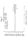
- Fig. 7 shows data obtained when a powder of Fe3O4, V2O5 and WO3 having an average particle diameter of 5 ⁇ m was added in the following various mixing ratios:
- a very small amount of at least one compound selected from the group consisting of vanadium compounds and tungsten compounds is added to a relatively small amount of an iron compound to thereby enable the rate at which the catalyst is poisoned by SOx to be lower than that in the case where an iron compound powder alone is employed. Accordingly, the life of the catalyst is greatly extended advantageously. In addition there is substantially no adverse affect on the boiler, furnace or the like. Thus, the present invention provides great industrial profitability.
Landscapes
- Chemical & Material Sciences (AREA)
- Engineering & Computer Science (AREA)
- Chemical Kinetics & Catalysis (AREA)
- Environmental & Geological Engineering (AREA)
- Organic Chemistry (AREA)
- Materials Engineering (AREA)
- Biomedical Technology (AREA)
- Oil, Petroleum & Natural Gas (AREA)
- General Chemical & Material Sciences (AREA)
- Analytical Chemistry (AREA)
- Health & Medical Sciences (AREA)
- Exhaust Gas Treatment By Means Of Catalyst (AREA)
- Catalysts (AREA)
Priority Applications (1)
| Application Number | Priority Date | Filing Date | Title |
|---|---|---|---|
| AT87111769T ATE86518T1 (de) | 1986-08-15 | 1987-08-13 | Methode, um die desaktivierung von entstickungskatalysatoren zu verhindern. |
Applications Claiming Priority (4)
| Application Number | Priority Date | Filing Date | Title |
|---|---|---|---|
| JP191514/86 | 1986-08-15 | ||
| JP61191514A JPS6349233A (ja) | 1986-08-15 | 1986-08-15 | 石炭の脱硝触媒劣化抑制方法 |
| JP62086170A JPS63252531A (ja) | 1987-04-08 | 1987-04-08 | 脱硝触媒の劣化抑制方法 |
| JP86170/87 | 1987-04-08 |
Publications (2)
| Publication Number | Publication Date |
|---|---|
| EP0256529A1 true EP0256529A1 (fr) | 1988-02-24 |
| EP0256529B1 EP0256529B1 (fr) | 1993-03-10 |
Family
ID=26427328
Family Applications (1)
| Application Number | Title | Priority Date | Filing Date |
|---|---|---|---|
| EP87111769A Expired - Lifetime EP0256529B1 (fr) | 1986-08-15 | 1987-08-13 | Méthode pour empêcher la désactivation d'un catalyseur de dénitration |
Country Status (6)
| Country | Link |
|---|---|
| US (1) | US4831942A (fr) |
| EP (1) | EP0256529B1 (fr) |
| KR (1) | KR930005291B1 (fr) |
| CN (1) | CN1008073B (fr) |
| AU (1) | AU597405B2 (fr) |
| DE (1) | DE3784586T2 (fr) |
Cited By (4)
| Publication number | Priority date | Publication date | Assignee | Title |
|---|---|---|---|---|
| FR2640160A1 (fr) * | 1988-12-12 | 1990-06-15 | United Technologies Corp | Procede de fabrication d'un catalyseur en oxyde de fer, utilisable notamment dans un propergol solide de moteur-fusee |
| EP1970429A3 (fr) * | 2007-03-16 | 2009-01-21 | Afton Chemical Corporation | Fourniture de tungstène à un système de combustion ou flux d'échappement d'un système de combustion contenant du fer |
| EP2444142A3 (fr) * | 2010-10-21 | 2014-01-22 | Babcock and Wilcox Power Generation Group, Inc. | Système et procédé de protection de catalyseur SCR et contrôle de plusieurs émissions |
| CN112844042A (zh) * | 2021-01-29 | 2021-05-28 | 中冶华天工程技术有限公司 | 防止粘性粉尘堵塞脱硝催化剂的方法及系统 |
Families Citing this family (24)
| Publication number | Priority date | Publication date | Assignee | Title |
|---|---|---|---|---|
| US5101743A (en) * | 1990-12-04 | 1992-04-07 | Amoco Corporation | Fluid bed incineration |
| US5095827A (en) * | 1991-03-05 | 1992-03-17 | Williams Robert M | Apparatus for reducing the moisture content in combustible material by utilizing the heat from combustion of such material |
| RU2107223C1 (ru) * | 1996-08-15 | 1998-03-20 | МГВП "Политехэнерго" | Топка |
| US6328911B1 (en) * | 2000-02-15 | 2001-12-11 | The Regents Of The University Of California | Method for the prevention of high temperature corrosion due to alkali sulfates and chlorides and composition for use in the same |
| US8124036B1 (en) | 2005-10-27 | 2012-02-28 | ADA-ES, Inc. | Additives for mercury oxidation in coal-fired power plants |
| US6729248B2 (en) | 2000-06-26 | 2004-05-04 | Ada Environmental Solutions, Llc | Low sulfur coal additive for improved furnace operation |
| US8439989B2 (en) * | 2000-06-26 | 2013-05-14 | ADA-ES, Inc. | Additives for mercury oxidation in coal-fired power plants |
| US6484651B1 (en) * | 2000-10-06 | 2002-11-26 | Crown Coal & Coke Co. | Method for operating a slag tap combustion apparatus |
| GB0902517D0 (en) | 2009-02-16 | 2009-04-01 | Innospec Ltd | Improvements in or relating to the combustion of coal |
| US10213738B2 (en) | 2009-04-22 | 2019-02-26 | The Babcock & Wilcox Company | System and method for increasing the service life and/or catalytic activity of an SCR catalyst and control of multiple emissions |
| US8691719B2 (en) * | 2009-04-22 | 2014-04-08 | Babcock & Wilcox Power Generation Group, Inc. | System and method for increasing the service life and/or catalytic activity of an SCR catalyst and control of multiple emissions |
| US8716169B2 (en) * | 2009-04-22 | 2014-05-06 | Babcock & Wilcox Power Generation Group, Inc. | System and method for protection of SCR catalyst and control of multiple emissions |
| US10471384B2 (en) | 2009-04-22 | 2019-11-12 | The Babcock & Wilcox Company | System and method for reducing halogen levels necessary for mercury control, increasing the service life and/or catalytic activity of an SCR catalyst and/or control of multiple emissions |
| US8784757B2 (en) | 2010-03-10 | 2014-07-22 | ADA-ES, Inc. | Air treatment process for dilute phase injection of dry alkaline materials |
| CA2792732C (fr) | 2010-03-10 | 2018-07-31 | Martin A. Dillon | Procede d'injection en phase diluee de matieres alcalines seches |
| US9017452B2 (en) | 2011-11-14 | 2015-04-28 | ADA-ES, Inc. | System and method for dense phase sorbent injection |
| US8974756B2 (en) | 2012-07-25 | 2015-03-10 | ADA-ES, Inc. | Process to enhance mixing of dry sorbents and flue gas for air pollution control |
| CN103768939A (zh) * | 2013-12-31 | 2014-05-07 | 杭州天蓝环保设备有限公司 | 一种脱硝增效剂及sncr脱硝增效方法 |
| US10350545B2 (en) | 2014-11-25 | 2019-07-16 | ADA-ES, Inc. | Low pressure drop static mixing system |
| TWI611837B (zh) * | 2016-09-23 | 2018-01-21 | 絲芙芮生醫科技有限公司 | 新穎催化劑之用途及使用該催化劑處理印刷電路板含油墨膠渣廢料之方法 |
| CN111054151B (zh) * | 2019-12-19 | 2024-09-10 | 安徽意义环保工程有限公司 | 一种脱硝除尘一体化及气流均布装置 |
| CN111044668B (zh) * | 2019-12-26 | 2022-12-02 | 中国华电科工集团有限公司 | 一种scr脱硝系统催化剂寿命在线预测方法 |
| CN114307600B (zh) * | 2021-12-22 | 2023-02-03 | 北京中德华信能源科技有限公司 | 一种脱硫增效添加剂 |
| CN117732476A (zh) * | 2023-12-14 | 2024-03-22 | 嘉庚创新实验室 | 催化剂的制备方法、催化剂及其应用 |
Family Cites Families (8)
| Publication number | Priority date | Publication date | Assignee | Title |
|---|---|---|---|---|
| US4173454A (en) * | 1977-07-18 | 1979-11-06 | Heins Sidney M | Method for removal of sulfur from coal in stoker furnaces |
| US4381718A (en) * | 1980-11-17 | 1983-05-03 | Carver George P | Low emissions process and burner |
| US4388877A (en) * | 1981-07-07 | 1983-06-21 | Benmol Corporation | Method and composition for combustion of fossil fuels in fluidized bed |
| JPS59230623A (ja) * | 1983-06-14 | 1984-12-25 | Mitsubishi Heavy Ind Ltd | 脱硝触媒の長寿命化方法 |
| JPS60202741A (ja) * | 1984-03-28 | 1985-10-14 | Mitsubishi Heavy Ind Ltd | 脱硝触媒の処理方法 |
| US4572085A (en) * | 1985-02-06 | 1986-02-25 | Amax Inc. | Coal combustion to produce clean low-sulfur exhaust gas |
| JPH0644591A (ja) * | 1991-10-21 | 1994-02-18 | Nec Home Electron Ltd | 分離型光ヘッド |
| JPH0664111A (ja) * | 1992-08-24 | 1994-03-08 | Toppan Printing Co Ltd | 紙容器 |
-
1987
- 1987-08-13 AU AU76862/87A patent/AU597405B2/en not_active Ceased
- 1987-08-13 DE DE87111769T patent/DE3784586T2/de not_active Expired - Fee Related
- 1987-08-13 EP EP87111769A patent/EP0256529B1/fr not_active Expired - Lifetime
- 1987-08-14 CN CN87106413A patent/CN1008073B/zh not_active Expired
- 1987-08-14 KR KR1019870008937A patent/KR930005291B1/ko not_active Expired - Fee Related
- 1987-08-17 US US07/086,317 patent/US4831942A/en not_active Expired - Fee Related
Non-Patent Citations (4)
| Title |
|---|
| PATENT ABSTRACTS OF JAPAN, vol. 10, no. 63 (C-332)[2120], 13th March 1986; & JP-A-60 202 741 (MITSUBISHI JUKOGYO K.K.) 14-10-1985 * |
| PATENT ABSTRACTS OF JAPAN, vol. 8, no. 138 (C-231)[1575], 27th June 1984; & JP-A-59 49 847 (NIHON GAISHI K.K.) 22-03-1984 * |
| PATENT ABSTRACTS OF JAPAN, vol. 9, no. 171 (C-291)[1894], 16th July 1985; & JP-A-60 44 040 (MITSUBISHI JUKOGYO K.K.) 08-03-1985 * |
| PATENT ABSTRACTS OF JAPAN, vol. 9, no. 175 (C-292)[1898], 19th July 1985; & JP-A-60 44 591 (MITSUBISHI JUKOGYO K.K.) 09-03-1985 * |
Cited By (8)
| Publication number | Priority date | Publication date | Assignee | Title |
|---|---|---|---|---|
| FR2640160A1 (fr) * | 1988-12-12 | 1990-06-15 | United Technologies Corp | Procede de fabrication d'un catalyseur en oxyde de fer, utilisable notamment dans un propergol solide de moteur-fusee |
| US5047382A (en) * | 1988-12-12 | 1991-09-10 | United Technologies Corporation | Method for making iron oxide catalyst |
| EP1970429A3 (fr) * | 2007-03-16 | 2009-01-21 | Afton Chemical Corporation | Fourniture de tungstène à un système de combustion ou flux d'échappement d'un système de combustion contenant du fer |
| US7794512B2 (en) | 2007-03-16 | 2010-09-14 | Afton Chemical Corporation | Supplying tungsten to a combustion system or combustion system exhaust stream containing iron |
| EP2444142A3 (fr) * | 2010-10-21 | 2014-01-22 | Babcock and Wilcox Power Generation Group, Inc. | Système et procédé de protection de catalyseur SCR et contrôle de plusieurs émissions |
| EP3156117A1 (fr) * | 2010-10-21 | 2017-04-19 | The Babcock & Wilcox Company | Procéde de protection de catalyseur scr et réglage de plusieurs émissions |
| CN112844042A (zh) * | 2021-01-29 | 2021-05-28 | 中冶华天工程技术有限公司 | 防止粘性粉尘堵塞脱硝催化剂的方法及系统 |
| CN112844042B (zh) * | 2021-01-29 | 2023-04-25 | 中冶华天工程技术有限公司 | 防止粘性粉尘堵塞脱硝催化剂的方法及系统 |
Also Published As
| Publication number | Publication date |
|---|---|
| DE3784586D1 (de) | 1993-04-15 |
| CN1008073B (zh) | 1990-05-23 |
| AU597405B2 (en) | 1990-05-31 |
| KR880002980A (ko) | 1988-05-12 |
| CN87106413A (zh) | 1988-06-08 |
| AU7686287A (en) | 1988-02-18 |
| KR930005291B1 (ko) | 1993-06-17 |
| US4831942A (en) | 1989-05-23 |
| EP0256529B1 (fr) | 1993-03-10 |
| DE3784586T2 (de) | 1993-10-14 |
Similar Documents
| Publication | Publication Date | Title |
|---|---|---|
| EP0256529B1 (fr) | Méthode pour empêcher la désactivation d'un catalyseur de dénitration | |
| EP0258708B1 (fr) | Procédé pour le contrôle de la formation de scories provenant des cendres volantes de charbon | |
| US6054408A (en) | Catalyst for reducing the nitrogen oxide concentration in a flowing medium and method for producing the catalyst | |
| US3837820A (en) | Combustion control by additives introduced in both hot and cold zones | |
| Srivastava et al. | Nitrogen oxides emission control options for coal-fired electric utility boilers | |
| US8293196B1 (en) | Additives for mercury oxidation in coal-fired power plants | |
| US8439989B2 (en) | Additives for mercury oxidation in coal-fired power plants | |
| US5658547A (en) | Simplified efficient process for reducing NOx, SOx, and particulates | |
| CA2596893C (fr) | Injection cible de reduction a so3 | |
| US4616574A (en) | Process for treating combustion systems with pressure-hydrated dolomitic lime | |
| US4891348A (en) | Catalyst for removing nitrogen oxides in exhaust gases | |
| KR20230091756A (ko) | Sncr-scr 하이브리드 질소산화물 저감 시스템 | |
| JPS63501031A (ja) | 窒素およびイオウを含有する燃料の燃焼時に酸化窒素および酸化イオウの排出を減少させる方法 | |
| EP0753701B1 (fr) | Chaudière avec appareil de dénitrification | |
| KR20140033069A (ko) | 피독에 대한 개선된 내성을 가진 촉매 | |
| US6612249B2 (en) | Zero NOx gaseous passivation process | |
| KR20040026653A (ko) | 암모니아 함유 배출 가스의 처리 방법 | |
| JPH0367729B2 (fr) | ||
| CA1245449A (fr) | Composition et methode pour le captage du soufre | |
| JPH0261293B2 (fr) | ||
| FI89741C (fi) | Saett att driva ett kraftverk | |
| JP7587225B2 (ja) | 燃焼システム | |
| JPH0696089B2 (ja) | 流動層ボイラにおける高効率脱硫脱硝方法 | |
| JPH0633373B2 (ja) | 燃料添加剤用鉄酸化物及びその使用方法 | |
| GAO et al. | Performance of a New Copper-based Sorbent with the Addition of Potassium Sulfate for SO2/NO-removal in a Powder-particle Fluidized Bed |
Legal Events
| Date | Code | Title | Description |
|---|---|---|---|
| PUAI | Public reference made under article 153(3) epc to a published international application that has entered the european phase |
Free format text: ORIGINAL CODE: 0009012 |
|
| AK | Designated contracting states |
Kind code of ref document: A1 Designated state(s): AT BE DE FR GB IT LU NL SE |
|
| 17P | Request for examination filed |
Effective date: 19880729 |
|
| 17Q | First examination report despatched |
Effective date: 19910108 |
|
| RTI1 | Title (correction) | ||
| ITTA | It: last paid annual fee | ||
| ITF | It: translation for a ep patent filed | ||
| GRAA | (expected) grant |
Free format text: ORIGINAL CODE: 0009210 |
|
| RAP1 | Party data changed (applicant data changed or rights of an application transferred) |
Owner name: TOA NEKKEN CORP., LTD. |
|
| AK | Designated contracting states |
Kind code of ref document: B1 Designated state(s): AT BE DE FR GB IT LU NL SE |
|
| REF | Corresponds to: |
Ref document number: 86518 Country of ref document: AT Date of ref document: 19930315 Kind code of ref document: T |
|
| REF | Corresponds to: |
Ref document number: 3784586 Country of ref document: DE Date of ref document: 19930415 |
|
| ET | Fr: translation filed | ||
| PLBE | No opposition filed within time limit |
Free format text: ORIGINAL CODE: 0009261 |
|
| STAA | Information on the status of an ep patent application or granted ep patent |
Free format text: STATUS: NO OPPOSITION FILED WITHIN TIME LIMIT |
|
| 26N | No opposition filed | ||
| EPTA | Lu: last paid annual fee | ||
| EAL | Se: european patent in force in sweden |
Ref document number: 87111769.3 |
|
| PGFP | Annual fee paid to national office [announced via postgrant information from national office to epo] |
Ref country code: SE Payment date: 19980622 Year of fee payment: 12 |
|
| PGFP | Annual fee paid to national office [announced via postgrant information from national office to epo] |
Ref country code: GB Payment date: 19980803 Year of fee payment: 12 Ref country code: AT Payment date: 19980803 Year of fee payment: 12 |
|
| PGFP | Annual fee paid to national office [announced via postgrant information from national office to epo] |
Ref country code: LU Payment date: 19980807 Year of fee payment: 12 |
|
| PGFP | Annual fee paid to national office [announced via postgrant information from national office to epo] |
Ref country code: NL Payment date: 19980828 Year of fee payment: 12 Ref country code: FR Payment date: 19980828 Year of fee payment: 12 Ref country code: BE Payment date: 19980828 Year of fee payment: 12 |
|
| PGFP | Annual fee paid to national office [announced via postgrant information from national office to epo] |
Ref country code: DE Payment date: 19981020 Year of fee payment: 12 |
|
| PG25 | Lapsed in a contracting state [announced via postgrant information from national office to epo] |
Ref country code: LU Free format text: LAPSE BECAUSE OF NON-PAYMENT OF DUE FEES Effective date: 19990813 Ref country code: GB Free format text: LAPSE BECAUSE OF NON-PAYMENT OF DUE FEES Effective date: 19990813 Ref country code: AT Free format text: LAPSE BECAUSE OF NON-PAYMENT OF DUE FEES Effective date: 19990813 |
|
| PG25 | Lapsed in a contracting state [announced via postgrant information from national office to epo] |
Ref country code: SE Free format text: THE PATENT HAS BEEN ANNULLED BY A DECISION OF A NATIONAL AUTHORITY Effective date: 19990814 |
|
| PG25 | Lapsed in a contracting state [announced via postgrant information from national office to epo] |
Ref country code: BE Free format text: LAPSE BECAUSE OF NON-PAYMENT OF DUE FEES Effective date: 19990831 |
|
| BERE | Be: lapsed |
Owner name: TOA NEKKEN CORP. LTD Effective date: 19990831 |
|
| PG25 | Lapsed in a contracting state [announced via postgrant information from national office to epo] |
Ref country code: NL Free format text: LAPSE BECAUSE OF NON-PAYMENT OF DUE FEES Effective date: 20000301 |
|
| GBPC | Gb: european patent ceased through non-payment of renewal fee |
Effective date: 19990813 |
|
| PG25 | Lapsed in a contracting state [announced via postgrant information from national office to epo] |
Ref country code: FR Free format text: LAPSE BECAUSE OF NON-PAYMENT OF DUE FEES Effective date: 20000428 |
|
| EUG | Se: european patent has lapsed |
Ref document number: 87111769.3 |
|
| NLV4 | Nl: lapsed or anulled due to non-payment of the annual fee |
Effective date: 20000301 |
|
| PG25 | Lapsed in a contracting state [announced via postgrant information from national office to epo] |
Ref country code: DE Free format text: LAPSE BECAUSE OF NON-PAYMENT OF DUE FEES Effective date: 20000601 |
|
| REG | Reference to a national code |
Ref country code: FR Ref legal event code: ST |
|
| PG25 | Lapsed in a contracting state [announced via postgrant information from national office to epo] |
Ref country code: IT Free format text: LAPSE BECAUSE OF NON-PAYMENT OF DUE FEES;WARNING: LAPSES OF ITALIAN PATENTS WITH EFFECTIVE DATE BEFORE 2007 MAY HAVE OCCURRED AT ANY TIME BEFORE 2007. THE CORRECT EFFECTIVE DATE MAY BE DIFFERENT FROM THE ONE RECORDED. Effective date: 20050813 |