EP0256795A2 - Appareil pour accélérer d'une manière variable un organe d'entraînement rotatif - Google Patents
Appareil pour accélérer d'une manière variable un organe d'entraînement rotatif Download PDFInfo
- Publication number
- EP0256795A2 EP0256795A2 EP87306998A EP87306998A EP0256795A2 EP 0256795 A2 EP0256795 A2 EP 0256795A2 EP 87306998 A EP87306998 A EP 87306998A EP 87306998 A EP87306998 A EP 87306998A EP 0256795 A2 EP0256795 A2 EP 0256795A2
- Authority
- EP
- European Patent Office
- Prior art keywords
- drive member
- planet gear
- rotation
- axis
- sun gear
- Prior art date
- Legal status (The legal status is an assumption and is not a legal conclusion. Google has not performed a legal analysis and makes no representation as to the accuracy of the status listed.)
- Granted
Links
Images



Classifications
-
- B—PERFORMING OPERATIONS; TRANSPORTING
- B65—CONVEYING; PACKING; STORING; HANDLING THIN OR FILAMENTARY MATERIAL
- B65H—HANDLING THIN OR FILAMENTARY MATERIAL, e.g. SHEETS, WEBS, CABLES
- B65H29/00—Delivering or advancing articles from machines; Advancing articles to or into piles
- B65H29/38—Delivering or advancing articles from machines; Advancing articles to or into piles by movable piling or advancing arms, frames, plates, or like members with which the articles are maintained in face contact
- B65H29/40—Members rotated about an axis perpendicular to direction of article movement, e.g. star-wheels formed by S-shaped members
-
- B—PERFORMING OPERATIONS; TRANSPORTING
- B65—CONVEYING; PACKING; STORING; HANDLING THIN OR FILAMENTARY MATERIAL
- B65H—HANDLING THIN OR FILAMENTARY MATERIAL, e.g. SHEETS, WEBS, CABLES
- B65H29/00—Delivering or advancing articles from machines; Advancing articles to or into piles
- B65H29/68—Reducing the speed of articles as they advance
-
- F—MECHANICAL ENGINEERING; LIGHTING; HEATING; WEAPONS; BLASTING
- F16—ENGINEERING ELEMENTS AND UNITS; GENERAL MEASURES FOR PRODUCING AND MAINTAINING EFFECTIVE FUNCTIONING OF MACHINES OR INSTALLATIONS; THERMAL INSULATION IN GENERAL
- F16H—GEARING
- F16H35/00—Gearings or mechanisms with other special functional features
- F16H35/02—Gearings or mechanisms with other special functional features for conveying rotary motion with cyclically varying velocity ratio
Definitions
- This invention relates to apparatus for variably accelerating a rotatable drive member and in particular to a decelerating apparatus for receiving a high speed product and delivering it at a relatively lower speed. More particularly the invention relates to an apparatus for decelerating printed copies received from a folding mechanism which are then to be delivered at a relatively lower speed onto and synchronous with a conveyor belt on which the copies must be laid in a controlled manner.
- the printed copies are folded by a folding mechanism and emitted therefrom at high speed.
- the direction of travel of the emitted printed copy must then be changed through 90° and also the speed of the copy reduced to the lower speed of a conveyor belt on which the copies must be laid in a controlled manner.
- an apparatus to both receive the high speed copies and decelerate them in a controlled manner and to deliver the slower moving copies onto a conveyor belt in a neat fashion without intefering with the laid copies.
- Prior art slow down apparatus has employed designs to slow down the copies by impacting upon slower moving and or static stops leading to uncontrolled slowing down of the copies which can cause damage.
- the slow down apparatus has been unable to achieve the required performance characteristics with controlled copy kinematics.
- the complex prior art slow down apparatus are both difficult and expensive to produce. There is therefore a need for an apparatus to provide controlled deceleration of the copy.
- apparatus for variably accelerating a rotatable drive member comprising a planetry gear system having a sun gear with planet gear arranged to orbit therearound in use, a rotation element located off axis relative to the planet gear axis but being rotatably driven by the planet gear orbitting, and the drive member being linked for rotation by the movement of the rotation element.
- variable velocity the drive member rotates with a variable velocity between a maximum and minimum velocity.
- acceleration of the drive member is variable.
- variable acceleration encompasses the term positive acceleration, and negative acceleration or deceleration.
- the variable velocity movement of the drive member can be employed in many ways to accelerate products or decelerate them.
- the orbit velocity about the sun gear axis of the rotation element is greater when its passage with regard to the planet gear is remote from the axis of the sun gear.
- the minimum orbit velocity about the sun gear axis occurs when the planet gear rotation during orbit brings the rotation element closest to the sun gear.
- the drive member can be arranged to rotate a drive shaft operating a belt system which may be employed in an apparatus to decelerate printed copies received from a folding mechanism.
- the drive member can be employed to accelerate copies within known conveyor and bundling equipment in the printing industry.
- the rotation element comprises at least one cam, a single can being rotatably mounted on the or each planet gear; and the drive member is rotatably mounted on the sun gear axis and includes slot means formed for slidably receiving the or each cam.
- the cam rotates about the planet gear axis, it acts to cause the drive member to rotate about the sun gear axis and at the same time slides towards and away from the sun gear axis within the slot means.
- the rotation of the drive member has a variable velocity about sun gear axis, inbetween a maximum and minium velocity.
- any indirectly or directly driven gear can be simply arranged to catch products at a high speed and deliver them at a low speed or catch products at a low speed and deliver them at a high speed.
- the choice of direct and indirect drive will be apparent to a person skilled in the art.
- An alternative apparatus has the rotation element comprising at least one crank, a single crank having one end mounted to the axis of the or each planet gear and the other end of the crank being offset relative to the planet gear axis; and the drive member is rotatably mounted on the sun gear axis and is rotated by the movement of said other end of the or each crank.
- the other end of the or each crank caninclude a cam and the drive member can include a slot means formed for slidably receiving the or each cam.
- the drive member can include slide menas capable of sliding movement towards and away from the sun axis, the slide means receiving the other end of the crank. This latter embodiment provides more uniform kinematics.
- two planet gears are provided, preferably on opposite sides of the sun axis. Consequently, the movement of the rotation elements is balanced about the sun gear as the drive member rotates.
- a further drive member is rotatably mounted on the sun gear axis, the further drive member being linked for rotation by one or more further rotation elements mounted offset to the or each planet gear in manner to provide rotational movement in counterpoint to the movement from the or each first mentioned rotation element on that planet gear.
- a further drive member is rotatably mounted on the sun gear axis, the further drive member being linked for rotation by one or more rotation elements, each mounted to a respective extra planet gear arranged to orbit the sun gear, the further rotation elements being mounted on the extra planet gear offset relative to the extra planet gear axis to provide rotational movement in counterpoint to the movement from the or each first mentioned rotation element.
- inventions have the advantage that a variable velocity between a maximum and a minimum velocity can be provided which is directly opposite to that provided from the first mentioned rotation elements.
- the further drive member can be mechanically linked to a counterbalance provided to balance inertia changes transmitted to the first mentioned drive member.
- a counter weight can be simply provided and driven by the further drive member, which counterweight movement reduces the stresses on the apparatus resulting from changes in energy given and received by elements rotated by the drive member, which changes result from the variable rotation velocity thereof.
- the first mentioned drive member is mechanically linked to drive a drive shaft having mounted thereon gripper means defining a circumferential path about the drive shaft during rotation, the gripper means being operable to grip and release a received product during passage about the circumferential path.
- the gripper means are conveniently mounted on at least two hubs fixedly mounted on said drive shaft, each hub including a respective gripper means for gripping a received product and wherein the space between said hubs is adjusatible along the drive shaft.
- the width of the product received can be simply changed by the movement of the hubs along the path in a manner to optimise the gipping effect dependant on the size of the received product.
- the apparatus comprises a printed product decelerating apparatus.
- the present apparatus is considerably simpler than hitherto known apparatus thereby reducing the cost of the apparatus and improving the effectiveness of the deceleration of the received products. It should be noted that if the gripper means is arranged to release the received product at the gripper means miminum velocity point, then immediately thereafter, the gripper means accelerates away from the released product thereby ensuring a cleans release of the product.
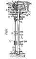
- a drive shaft 1 has mounted thereon a pair of hubs 2, 2 ⁇ , each with a pair of gripping arrangements 3 provided at opposing circumferential positions. These have been omitted from Figure 1 for the purposes of clarity.
- Each of the hubs 2 are located onto the shaft 1 and are also fixed to a further shaft 20 extending between end plates 21 and 22 which are mounted to the drive shaft 1 so that the shaft 20 rotates with the hubs 2 and 2 ⁇ .
- the hubs 2 and 2 ⁇ are slidably mounted on the shaft 1 but are locked to the rotation of the shaft 1 by means of a key screw 23 in shaft 1.
- the position of the hubs 2 and 2 ⁇ on the shaft 20 can be adjusted by releasing the key screw 23 which can be urged into contact with the shaft 1 to lock the position of the hub 2 to the position on the shaft 1.
- a similar adjusting means can also be provided on the hub 2 ⁇ but has been omitted from Figure 1 for the purposes of clarity. Consequently, the distance between the two hubs 2 and 2 ⁇ , and hence the gripping means thereon can be adjusted to allow different width printed copies to be received by the apparatus.
- a printed product for example that issuing from a folding cylinder making a first cross fold, sends the printed product in the direction of arrow 4 between a conveyor belt 5 and a fixed side member 6.
- the printed product falls with high velocity to be received by one of the respective grippers mounted on the hubs 2 and 2 ⁇ .
- the grippers 3 are arranged to be in their open position when they rotate to a position of about 4 O'Clock relative to the upward direction of Figure 2.As will be apparent to a person skilled in the art, by means of suitable cams, the gripper means 3 are arranged to close immediately thereafter so that a printed product is gripped between the gripper 3 and the outer circumference of the hubs 2, 2 ⁇ .
- the shaft 1 is mounted for rotation in bearings 7 at one end towards plate 21 and bearings 8 at the other end towards plate 20.
- rotation of the shaft 1 also rotates the hubs 2 and 2 ⁇ .
- the cam arrangement is arranged to cause the gripper means to open so that the printed product held therein is delivered onto a conveyor belt 10 located immediately below the hubs. It can be seen that the cams are arranged to close and open the gripper means 3 at approximately 90° intervals around the axis of the drive shaft 1. It will be apparent that the copy is positively gripped throughout the deceleration process so that the copy cannot deviate from its prescribed path.
- the printed product emerging in the direction of arrow 4 has a considerable velocity compared with the velocity of the conveyor belt 10.
- the rotation of the hubs 2 and 2 ⁇ needs to be variable to accept the product from the direction of arrow 4 with a high velocity but to then slow rotational movement to deliver the printed product to the conveyor belt with substantially the same speed as that of the conveyor belt 10.
- This receipt and delivery must also occur with a predetermined periodicity.
- the drive shaft 1 must be driven in order to achieve an angular velocity profile of the grippers 3 substantially as that shown in Figure 4.
- a planetary gear system is provided around the shaft 1.
- a fixed sun gear 30 is mounted on bearings 11 so that the sun gear does not rotate with the drive shaft 1.
- Two opposingly situated planet gears 12 are mounted to mesh with the sun gear 30 and are driven by an annular gear 13. This annular gear is driven by an external gear 14 with a rotational velocity w.
- Each planet gear has a cam member 14 mounted off axis in a symmetrical manner with each other.
- a slotted drive member 15 is fixed to the drive shaft 1 in a manner whereby the slots receive the cam members 14 which typically comprise rotatable discs.
- the annular gear 13 is driven with an angular velocity w which imparts rotation to the planet gears 12.
- the rotation of the planet gear causes the cam members 14 to act on the drive member 15 to rotate it with an angular velocity It will be apparent that as the planet gears rotate, the cam members 14 travel towards and away from the sun gear 30 as well as orbiting therearound This movment causes the actual rotational movement applied to the drive member 15 to vary.
- Maximum and minimum angular velocity are determined from the following formula, where "r", is negative at its closest position to shaft 1.
- the drive member 15 executes a velocity pattern identical with that of Figure 4 and since the drive member 15 is fixed to the drive shaft 1, the rotation of the driver member 15 is replicated in the rotation of the hubs 2 and 2 ⁇ . It will be apparent that the rotation of the drive member 15 could be achieved by the use of one planet gear or alternatively four planet gears phased together to give the same effect.
- each planetary gear 12 includes a further cam member 16 mounted thereon so that when the cam member 14 is at its most remote position from the sun gear 1, the cam members 16 are located closest to the sun 30.
- a corresponding slotting drive member 17 is mounted on bearings 18 for rotation about the drive shaft 1.
- the drive member 17 includes a slot to receive the cam members 16 so taht the cam members act thereon to rotate the drive member 17.
- the drive member 17 is fixed to a counter weight 22 balancing the inertia of the hubs 2 and 2 ⁇ .
- the rotation of the drive member 17 by the cams 16 is out of phase with the rotation of the drive member 15 so that the rotation of the counter balance 22 balances the rotation changes of the hubs 2 and 2 ⁇ , that is to say when the hubs 2 and 2 ⁇ slow down, the counter balance speeds up and vica versa.
- the counter balance receives the energy given up by the hubs in the first half of the cycle and returns that energy to those masses as they accelerate in the second half of the cycle. In this way, the effects of stress on the apparatus resulting from the energy changes in hubs 2 and 2 ⁇ are reduced.
- Both drive members 17 and 15 can include shims 19, as shown in Figure 3, which are employed to eliminate back lash in the rotation.
- the maximum speed of the grippers is approximately 20-25 % slower than the printed products being received in order to assure suitable docking between the gripper and the printed copy.
- the opening and closing of the gripper means 3 are not illustrated since the action of these do not impinge on the invention.
- the grippers are opened and closed by means of a cam follower arrangement driven by the main shaft 1.
- the preferred embodiment of the invention includes gripper means opened and closed by suitable cam arrangement.
- gripper means opened and closed by suitable cam arrangement.
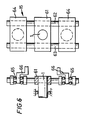
- the drive member comprises a drive block 61 fixed to the drive shaft 1.
- the rotation of the drive member 15 is replicated in the rotation of the hubs 2 and 2 ⁇ .
- the drive block 61 has a pair of fixed rods 62 and 63 each slidably mounting slide blocks 64 and 65.
- each block 64 includes a bearing 65 for receiving one end of a crank 66.
- Each crank 66 is fixed to the axis of a respective planet gear 12. It will be apparent that the location of the crank in bearing 65 is offset relative to the axis of teh planet gear 12.
- Figure 5 illustrates the embodiment fo Figure 6 wherein a further means of driving a counterbalance is provided.
- the sun gear 30 includes a pair of first planet gear 12 substantially as shown in Figure 3 and also further planet gear 12 ⁇ which are meshed with the planet gear 12.
- the planet gear 12 include the pair of cranks 66 to rotate drive member 15 whereas the planet gear 12 ⁇ include cranks 66 ⁇ which are arranged in a similar manner to that shown in Figure 6 but drive a further drive member schematically represented by the numeral 15 ⁇ .
- the crank 66 ⁇ is arranged in an opposite sense to that of crank 66 so that the drive member 15; has a rotational movement which is in counterpoint to the movement from the drive member 15.
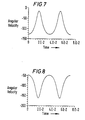
- the angular velocity and acceleration pattern is as shown in Figures 7 and 9 respectively which can be seen to be in opposition or in counterpoint to the angular velocity and acceleration pattern of a gripper means driven by the drive member 15.
- the present invention can take many different forms, which will be apparent to a person skilled in the art.
- suitable selection of the gearing of planetary gears 12 and sun gear 30 and annular gear 13 different numbers of velocity peaks can be produced during a single rotation of the hubs 2 and 2 ⁇ .
- the invention is preferably for use in the printing industry for receiving printed products in the grippers 3.
- the invention of receiving a rapidly moving product and slowing it down before delivery onto a conveyor means applies to many products.
Landscapes
- Engineering & Computer Science (AREA)
- Mechanical Engineering (AREA)
- General Engineering & Computer Science (AREA)
- Transmission Devices (AREA)
- Discharge By Other Means (AREA)
Applications Claiming Priority (2)
| Application Number | Priority Date | Filing Date | Title |
|---|---|---|---|
| GB8619504 | 1986-08-11 | ||
| GB868619504A GB8619504D0 (en) | 1986-08-11 | 1986-08-11 | Accelerating drive member |
Publications (3)
| Publication Number | Publication Date |
|---|---|
| EP0256795A2 true EP0256795A2 (fr) | 1988-02-24 |
| EP0256795A3 EP0256795A3 (en) | 1988-11-09 |
| EP0256795B1 EP0256795B1 (fr) | 1991-07-17 |
Family
ID=10602531
Family Applications (1)
| Application Number | Title | Priority Date | Filing Date |
|---|---|---|---|
| EP87306998A Expired EP0256795B1 (fr) | 1986-08-11 | 1987-08-07 | Appareil pour accélérer d'une manière variable un organe d'entraînement rotatif |
Country Status (5)
| Country | Link |
|---|---|
| US (1) | US4993702A (fr) |
| EP (1) | EP0256795B1 (fr) |
| JP (1) | JPS63115963A (fr) |
| DE (1) | DE3771414D1 (fr) |
| GB (1) | GB8619504D0 (fr) |
Cited By (3)
| Publication number | Priority date | Publication date | Assignee | Title |
|---|---|---|---|---|
| EP0484653A1 (fr) * | 1990-11-05 | 1992-05-13 | Heidelberger Druckmaschinen Aktiengesellschaft | Système de décélération dans une plieuse pour machine à imprimer rotative |
| EP0508572A1 (fr) * | 1991-02-22 | 1992-10-14 | Kabushiki Kaisha Toshiba | Appareil d'alimentation de matériaux en feuille |
| EP0972733A3 (fr) * | 1998-07-13 | 2000-10-11 | Heidelberger Druckmaschinen Aktiengesellschaft | Dispositif pour changer la vitesse d'exemplaires |
Families Citing this family (8)
| Publication number | Priority date | Publication date | Assignee | Title |
|---|---|---|---|---|
| FR2654981B1 (fr) * | 1989-11-28 | 1995-06-16 | Marinoni Harris Sa | Plieuse d'imprimerie. |
| US5326088A (en) * | 1992-08-27 | 1994-07-05 | Newsome John R | Apparatus for feeding signatures to a rotary drum with angularly spaced grippers |
| US5531433A (en) * | 1994-10-17 | 1996-07-02 | Am International, Inc. | Sheet material handling apparatus |
| DE10113165B4 (de) * | 2000-04-06 | 2014-05-15 | Heidelberger Druckmaschinen Ag | Einrichtung zur Überführung von Bogen |
| DE50304947D1 (de) * | 2003-05-20 | 2006-10-19 | Mueller Martini Holding Ag | Einrichtung zum Beschicken einer Verarbeitungsstrecke |
| JP2008504186A (ja) * | 2004-06-24 | 2008-02-14 | ゴス インターナショナル アメリカス インコーポレイテッド | 被印刷製品を供給するための方法及び装置 |
| EP2107021B1 (fr) * | 2008-04-03 | 2016-11-09 | Neopost Technologies | Dispositif pour rassembler des articles postaux et procédé correspondant |
| EP3843527B1 (fr) | 2018-08-29 | 2024-02-28 | CNH Industrial France S.A.S. | Unité de récolte |
Family Cites Families (32)
| Publication number | Priority date | Publication date | Assignee | Title |
|---|---|---|---|---|
| US1033968A (en) * | 1908-05-19 | 1912-07-30 | Franklin C Waldron | Wrapping or mailing machine. |
| US1063336A (en) * | 1910-01-15 | 1913-06-03 | Addressograph Co | Envelop-feeding mechanism. |
| US1365534A (en) * | 1920-08-14 | 1921-01-11 | Neihart Daniel | Sheet-feeding device |
| US2084783A (en) * | 1936-04-03 | 1937-06-22 | American Type Founders Inc | Printing press |
| US2248079A (en) * | 1939-09-15 | 1941-07-08 | Harris Seybold Potter Co | Sheet feeding mechanism |
| US2399493A (en) * | 1944-04-22 | 1946-04-30 | Cottrell C B & Sons Co | Change-speed mechanism |
| US2535774A (en) * | 1949-04-15 | 1950-12-26 | Etudes De Machines Speciales | Mechanism for converting a uniform motion into a variable motion |
| US2715975A (en) * | 1950-08-23 | 1955-08-23 | Cheshire Mailing Machines Inc | Label applying machines |
| DE1129029B (de) * | 1954-06-03 | 1962-05-03 | Saint Gobain | Umlaufkurbelgetriebe |
| US2956801A (en) * | 1958-04-23 | 1960-10-18 | Bemis Bro Bag Co | Bag manufacture |
| US3363482A (en) * | 1965-07-19 | 1968-01-16 | John S. Case | Power transmission arrangement |
| GB1217578A (en) * | 1968-03-22 | 1970-12-31 | Int Computers Ltd | Improvements in or relating to document feeding apparatus |
| DE1913844C3 (de) * | 1968-04-09 | 1973-10-25 | Adamovske Strojirny, N.P., Adamov (Tschechoslowakei) | Antriebsvorrichtung einer rotie renden Vorgreifertrommel mit Vorgreifern zur Anlage von Bogen an einem Zylinder |
| FR2050828A5 (fr) * | 1969-06-26 | 1971-04-02 | Palkhiwala Jagat | |
| GB1327882A (en) * | 1970-05-19 | 1973-08-22 | Windmoeller & Hoelscher | Apparatus for forming and conveying stacks of flat articles |
| GB1395725A (en) * | 1971-10-06 | 1975-05-29 | Beasley French & Co Ltd | Transmissions |
| DE2206682B2 (de) * | 1972-02-12 | 1976-09-09 | Windmöller & Hölscher, 4540 Lengerich | Vorrichtung zum bilden und weiterfoerdern von stapeln aus flachen werkstuecken |
| DE2224210C2 (de) * | 1972-05-18 | 1974-04-04 | Heidelberger Druckmaschinen Ag, 6900 Heidelberg | Antriebsvorrichtung für intermittierend umlaufende Anlegezylinder in Druck - und Stanzmaschinen |
| CH544026A (de) * | 1972-09-21 | 1973-11-15 | Grapha Holding Ag | Vorrichtung zum Umsetzen eines Papierbogenstapels in einen Schuppenstrom |
| IT991860B (it) * | 1973-07-25 | 1975-08-30 | Nebiolo Spa | Macchina rotativa da stampa per fogli singoli |
| US3955435A (en) * | 1974-10-18 | 1976-05-11 | Arick Robert E | Variable speed drive mechanism |
| IT1033362B (it) * | 1975-03-03 | 1979-07-10 | Omg Pessina Perobelli | Meccanismo per azionare con velcocita variabile il tamburo girevole di un metti foglio |
| US4334440A (en) * | 1978-10-10 | 1982-06-15 | Hugo Fonck | Automatic transmission |
| US4269076A (en) * | 1979-01-18 | 1981-05-26 | Easom Engineering & Manufacturing, Corp. | Motion generating mechanism |
| DE3036930C2 (de) * | 1980-09-30 | 1982-06-16 | Windmöller & Hölscher, 4540 Lengerich | Ungleichförmigkeitsgetriebe, vorzugsweise zum Antrieb von Messerwalzen |
| EP0075057B1 (fr) * | 1981-09-18 | 1986-01-29 | Maschinenfabrik GOEBEL GmbH | Mécanisme pour entraîner un appareil de délivrance de feuilles |
| FR2558556B1 (fr) * | 1984-01-23 | 1989-04-07 | Manutention Stockage Cie | Dispositif mecanique de transformation d'un mouvement circulaire a vitesse constante en mouvement circulaire a vitesse variable periodiquement |
| US4569240A (en) * | 1984-03-05 | 1986-02-11 | Easom Engineering & Manufacturing Corp. | Motion generating mechanism |
| JPS62269829A (ja) * | 1986-05-16 | 1987-11-24 | Yamada Kikai Kogyo Kk | シ−ト状物の供給装置 |
| DE3621385A1 (de) * | 1986-06-26 | 1988-01-14 | Roland Man Druckmasch | Vorrichtung zum antrieb eines schwingenden vorgreifers einer druckmaschine |
| JPS6357441A (ja) * | 1986-08-27 | 1988-03-12 | Mita Ind Co Ltd | シ−ト用送りロ−ラ |
| DE3726780A1 (de) * | 1987-08-12 | 1989-02-23 | Roland Man Druckmasch | Vorrichtung zur uebergabe von bogen |
-
1986
- 1986-08-11 GB GB868619504A patent/GB8619504D0/en active Pending
-
1987
- 1987-08-07 DE DE8787306998T patent/DE3771414D1/de not_active Expired - Lifetime
- 1987-08-07 EP EP87306998A patent/EP0256795B1/fr not_active Expired
- 1987-08-11 JP JP62200721A patent/JPS63115963A/ja active Pending
-
1989
- 1989-06-30 US US07/374,629 patent/US4993702A/en not_active Expired - Fee Related
Cited By (4)
| Publication number | Priority date | Publication date | Assignee | Title |
|---|---|---|---|---|
| EP0484653A1 (fr) * | 1990-11-05 | 1992-05-13 | Heidelberger Druckmaschinen Aktiengesellschaft | Système de décélération dans une plieuse pour machine à imprimer rotative |
| EP0508572A1 (fr) * | 1991-02-22 | 1992-10-14 | Kabushiki Kaisha Toshiba | Appareil d'alimentation de matériaux en feuille |
| US5224698A (en) * | 1991-02-22 | 1993-07-06 | Kabushiki Kaisha Toshiba | Apparatus for feeding sheet-like object |
| EP0972733A3 (fr) * | 1998-07-13 | 2000-10-11 | Heidelberger Druckmaschinen Aktiengesellschaft | Dispositif pour changer la vitesse d'exemplaires |
Also Published As
| Publication number | Publication date |
|---|---|
| EP0256795B1 (fr) | 1991-07-17 |
| JPS63115963A (ja) | 1988-05-20 |
| EP0256795A3 (en) | 1988-11-09 |
| US4993702A (en) | 1991-02-19 |
| DE3771414D1 (de) | 1991-08-22 |
| GB8619504D0 (en) | 1986-09-24 |
Similar Documents
| Publication | Publication Date | Title |
|---|---|---|
| EP0256795B1 (fr) | Appareil pour accélérer d'une manière variable un organe d'entraînement rotatif | |
| US6450321B1 (en) | Method and apparatus utilizing servo motors for placing parts onto a moving web | |
| US5417416A (en) | Apparatus for slowing down signatures sent to a quarter fold of a folder for a printing machine | |
| US4434979A (en) | Printed goods removal apparatus | |
| EP0254897A1 (fr) | Transmission pour la formation d'un mouvement de va-et-vient répétitif à partir d'un mouvement de rotation | |
| JPS60204568A (ja) | シ−ト製品を流れ状に供給して送り出す方法及び装置 | |
| US4600186A (en) | Method and apparatus for reducing the impact speed of a printed product which is delivered to a fly pocket of a fly delivery wheel in a rotary printing press | |
| GB1584225A (en) | Apparatuses for forming a succession of mutually overlapping folded printed products | |
| US5141221A (en) | Deceleration device in the folder of a rotary printing machine | |
| CA1287255C (fr) | Dispositif d'alimentation en feuilles pour machine d'impression | |
| EP0972733B1 (fr) | Dispositif pour changer la vitesse d'exemplaires | |
| JPS5926577B2 (ja) | ロ−ラ輪転印刷機用折たたみ機械 | |
| US3918313A (en) | Drive mechanism | |
| EP0181079A2 (fr) | Commande à soupapes variable | |
| EP1201586B1 (fr) | Méthode et dispositif pour faire varier la vitesse de produits en forme de feuilles | |
| US2226674A (en) | Sheet delivery mechanism | |
| EP1303240B1 (fr) | Procede et appareil utilisant des servomoteurs pour mettre en place des pieces sur une bande en defilement | |
| US2926909A (en) | Sheet transfer mechanism | |
| US5531433A (en) | Sheet material handling apparatus | |
| US6244593B1 (en) | Sheet diverter with non-uniform drive for signature collation and method thereof | |
| US2027818A (en) | Drive mechanism | |
| EP2878560B1 (fr) | Dispositif d'entraînement d'une paire de rouleaux pinceurs à vitesse de rotation variable | |
| US5813338A (en) | Gripper opening/closing mechanism of sheet transfer cylinder in sheet-fed printing machine | |
| US4459866A (en) | Non-uniform drive with balancing of masses | |
| EP0508572B1 (fr) | Appareil d'alimentation de matériaux en feuille |
Legal Events
| Date | Code | Title | Description |
|---|---|---|---|
| PUAI | Public reference made under article 153(3) epc to a published international application that has entered the european phase |
Free format text: ORIGINAL CODE: 0009012 |
|
| AK | Designated contracting states |
Kind code of ref document: A2 Designated state(s): CH DE FR GB IT LI SE |
|
| PUAL | Search report despatched |
Free format text: ORIGINAL CODE: 0009013 |
|
| AK | Designated contracting states |
Kind code of ref document: A3 Designated state(s): CH DE FR GB IT LI SE |
|
| 17P | Request for examination filed |
Effective date: 19890412 |
|
| 17Q | First examination report despatched |
Effective date: 19890731 |
|
| GRAA | (expected) grant |
Free format text: ORIGINAL CODE: 0009210 |
|
| AK | Designated contracting states |
Kind code of ref document: B1 Designated state(s): CH DE FR GB IT LI SE |
|
| PG25 | Lapsed in a contracting state [announced via postgrant information from national office to epo] |
Ref country code: IT Free format text: LAPSE BECAUSE OF FAILURE TO SUBMIT A TRANSLATION OF THE DESCRIPTION OR TO PAY THE FEE WITHIN THE PRE;WARNING: LAPSES OF ITALIAN PATENTS WITH EFFECTIVE DATE BEFORE 2007 MAY HAVE OCCURRED AT ANY TIME BEFORE 2007. THE CORRECT EFFECTIVE DATE MAY BE DIFFERENT FROM THE ONE RECORDED.SCRIBED TIME-LIMIT Effective date: 19910717 Ref country code: LI Effective date: 19910717 Ref country code: CH Effective date: 19910717 Ref country code: SE Effective date: 19910717 Ref country code: FR Effective date: 19910717 |
|
| REF | Corresponds to: |
Ref document number: 3771414 Country of ref document: DE Date of ref document: 19910822 |
|
| REG | Reference to a national code |
Ref country code: CH Ref legal event code: PL |
|
| EN | Fr: translation not filed | ||
| PLBE | No opposition filed within time limit |
Free format text: ORIGINAL CODE: 0009261 |
|
| STAA | Information on the status of an ep patent application or granted ep patent |
Free format text: STATUS: NO OPPOSITION FILED WITHIN TIME LIMIT |
|
| 26N | No opposition filed | ||
| REG | Reference to a national code |
Ref country code: GB Ref legal event code: 732E |
|
| REG | Reference to a national code |
Ref country code: GB Ref legal event code: IF02 |
|
| PGFP | Annual fee paid to national office [announced via postgrant information from national office to epo] |
Ref country code: GB Payment date: 20060825 Year of fee payment: 20 |
|
| PGFP | Annual fee paid to national office [announced via postgrant information from national office to epo] |
Ref country code: DE Payment date: 20061002 Year of fee payment: 20 |
|
| PG25 | Lapsed in a contracting state [announced via postgrant information from national office to epo] |
Ref country code: GB Free format text: LAPSE BECAUSE OF EXPIRATION OF PROTECTION Effective date: 20070806 |