EP0256807A2 - Optische Aufzeichnungskarte und Lesemethode - Google Patents
Optische Aufzeichnungskarte und Lesemethode Download PDFInfo
- Publication number
- EP0256807A2 EP0256807A2 EP87307018A EP87307018A EP0256807A2 EP 0256807 A2 EP0256807 A2 EP 0256807A2 EP 87307018 A EP87307018 A EP 87307018A EP 87307018 A EP87307018 A EP 87307018A EP 0256807 A2 EP0256807 A2 EP 0256807A2
- Authority
- EP
- European Patent Office
- Prior art keywords
- data
- pit
- pits
- column
- optical recording
- Prior art date
- Legal status (The legal status is an assumption and is not a legal conclusion. Google has not performed a legal analysis and makes no representation as to the accuracy of the status listed.)
- Granted
Links
Images




Classifications
-
- G—PHYSICS
- G06—COMPUTING OR CALCULATING; COUNTING
- G06K—GRAPHICAL DATA READING; PRESENTATION OF DATA; RECORD CARRIERS; HANDLING RECORD CARRIERS
- G06K7/00—Methods or arrangements for sensing record carriers, e.g. for reading patterns
- G06K7/10—Methods or arrangements for sensing record carriers, e.g. for reading patterns by electromagnetic radiation, e.g. optical sensing; by corpuscular radiation
- G06K7/14—Methods or arrangements for sensing record carriers, e.g. for reading patterns by electromagnetic radiation, e.g. optical sensing; by corpuscular radiation using light without selection of wavelength, e.g. sensing reflected white light
- G06K7/1404—Methods for optical code recognition
- G06K7/1439—Methods for optical code recognition including a method step for retrieval of the optical code
- G06K7/1443—Methods for optical code recognition including a method step for retrieval of the optical code locating of the code in an image
-
- G—PHYSICS
- G06—COMPUTING OR CALCULATING; COUNTING
- G06K—GRAPHICAL DATA READING; PRESENTATION OF DATA; RECORD CARRIERS; HANDLING RECORD CARRIERS
- G06K19/00—Record carriers for use with machines and with at least a part designed to carry digital markings
- G06K19/06—Record carriers for use with machines and with at least a part designed to carry digital markings characterised by the kind of the digital marking, e.g. shape, nature, code
- G06K19/08—Record carriers for use with machines and with at least a part designed to carry digital markings characterised by the kind of the digital marking, e.g. shape, nature, code using markings of different kinds or more than one marking of the same kind in the same record carrier, e.g. one marking being sensed by optical and the other by magnetic means
-
- G—PHYSICS
- G06—COMPUTING OR CALCULATING; COUNTING
- G06K—GRAPHICAL DATA READING; PRESENTATION OF DATA; RECORD CARRIERS; HANDLING RECORD CARRIERS
- G06K7/00—Methods or arrangements for sensing record carriers, e.g. for reading patterns
- G06K7/10—Methods or arrangements for sensing record carriers, e.g. for reading patterns by electromagnetic radiation, e.g. optical sensing; by corpuscular radiation
- G06K7/14—Methods or arrangements for sensing record carriers, e.g. for reading patterns by electromagnetic radiation, e.g. optical sensing; by corpuscular radiation using light without selection of wavelength, e.g. sensing reflected white light
-
- G—PHYSICS
- G06—COMPUTING OR CALCULATING; COUNTING
- G06K—GRAPHICAL DATA READING; PRESENTATION OF DATA; RECORD CARRIERS; HANDLING RECORD CARRIERS
- G06K7/00—Methods or arrangements for sensing record carriers, e.g. for reading patterns
- G06K7/10—Methods or arrangements for sensing record carriers, e.g. for reading patterns by electromagnetic radiation, e.g. optical sensing; by corpuscular radiation
- G06K7/14—Methods or arrangements for sensing record carriers, e.g. for reading patterns by electromagnetic radiation, e.g. optical sensing; by corpuscular radiation using light without selection of wavelength, e.g. sensing reflected white light
- G06K7/1404—Methods for optical code recognition
- G06K7/1439—Methods for optical code recognition including a method step for retrieval of the optical code
- G06K7/1456—Methods for optical code recognition including a method step for retrieval of the optical code determining the orientation of the optical code with respect to the reader and correcting therefore
-
- G—PHYSICS
- G11—INFORMATION STORAGE
- G11B—INFORMATION STORAGE BASED ON RELATIVE MOVEMENT BETWEEN RECORD CARRIER AND TRANSDUCER
- G11B7/00—Recording or reproducing by optical means, e.g. recording using a thermal beam of optical radiation by modifying optical properties or the physical structure, reproducing using an optical beam at lower power by sensing optical properties; Record carriers therefor
- G11B7/002—Recording, reproducing or erasing systems characterised by the shape or form of the carrier
- G11B7/0033—Recording, reproducing or erasing systems characterised by the shape or form of the carrier with cards or other card-like flat carriers, e.g. flat sheets of optical film
Definitions
- the present invention relates to an optical recording card.
- optical recording card is often used as synonymous with optical memory card.
- Cards of this type are recorded with various information such as personal data, company data and so on. Such information has been recorded at an earlier stage in the form of visible characters or symbols and at a later stage in the form of electric signals using magnetization. However, there is a need of preventing falsification and of increasing the amount of information.
- a laser card has recently been developed using the semi-conductor laser technology.
- a laser card is provided with information recording medium (optical recording medium) having an optical reflective surface on which concavity and convexity serving as data pits are formed. Data pits are detected to read the information, using a semiconductor laser in accordance with a difference in reflection factors of the concavity and convexity.
- an optical recording card 101 has a data truck 102 thereon.
- the data truck 102 has a plurality of pit columns 104d, 104e, 104f, 104g,... composed of a number of pits 103 aligned on a straight line in the column direction.
- the data truck is read one pit column after another with an optical reading element 106 by displacing the card 101.
- a number of optical reading elements 106 aligned on a straight line constitutes a line sensor 105.
- the line sensor 105 disposed over one pit column is sequentially scanned to read one pit column by one scan.
- Figs.13 and 14 show examples of arrangements of the pit column 104 and the line sensor 105 reading the pit column.
- the line sensor 105 Assuming the lateral width of the pit 103 is b and the length of the pit column 104 is c , if the inclination of the line sensor relative to the pit column becomes greater than an angle ⁇ , the line sensor 105 becomes displaced from one pit column to another. Thus, the line sensor 105 will read the gap between pit columns or the other pit column. Even if the inclination is smaller than ⁇ , the line sensor 105 may become displaced from a pit column to be read and may read the gap or the other pit column on condition a read start position d is near the other pit column.
- the present invention has been made in consideration of the above circumstances and seeks to provide an optical recording card and a method of reading the same which needs not an inclination correction even if the pit column on the data truck and a line sensor are disposed inclined, and can produce an alarm signal when a next pit column is read due to the inclination, to thereby attain a reading precision.
- the optical recording card of this invention is characterized in that a data truck is constructed of a number of pits in matrix arrangement and the start and end pits in each column of the data truck are used as discriminator pits.
- the optical recording card reading method wherein the optical recording card comprises a plurality of data pit groups with a guide bar interposed therebetween, each group having a plurality of data pits arranged in matrix of columns and rows and having discriminator pits at the start and end pits of each pit column, comprises the steps of: dividing data pit columns in accordance with a strobe signal from said guide bar, using a line sensor, a memory selector and a plurality of data processing memories; judging based upon a readout signal of said discriminator pits if each data pit column has been read correctly; and if the data pit column has been read correctly, causing said memory selector to select said data processing memories and writing the pit column data belonging to a same data pit group into a same data processing memory.
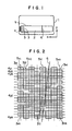
- a data truck 2 is provided on an optical recording card 1.
- Information written in the data truck 2 is an object to be read.
- the data truck 2 is composed of a plurality of pits 3 as shown in Figs. 2 and 3.
- a plurality of pits 3 are arranged in matrix of pit rows (4 y,1 , 4 y,2 . ...4 y,i ,...4 y,n ) and pit columns (5 x,1 , 5 x,2 ,...5 x,n ).
- pits 3 i,i represent the contents of information to be read except those start pits 3 1,1 , 3 2,1 ,...3 n,1 and those end pits 3 1,n , 3 2,n ,...3 n,n which are discriminator pits for indicating the position of the card 1.
- the start and end pits in each column have different binary values. For example, if the start discriminator pit 3 i,1 in a pit column 5 x,i is "1", the end discriminator pit 3 i,n is "0". Similarly, if the start discriminator pit 3 i+1,1 in a pit column 5 x,i+1 is "0", the end discriminator pit 3 i+1,n is "1".
- respective adjacent pits have different binary values. For example, if the discriminator pit 3 i,1 is "1", the adjacent discriminator pits 3 i-1,1 and 3 i+1,1 are "0".
- a pit row 4 y,n composed of the end discriminator pits 3 1,n , 3 2,n ,...3 n,n of pit columns, respective adjacent pits have different binary values. For example, since the discriminator pits 3 i,n is "0" in the above example, the discriminator pits 3 i-1,n and 3 i+1,n are "1".
- a line sensor 6 for reading data pits 3 has optical reading elements 7 (7a, 7b, 7c, 7d, 7e...) disposed densely in the Y-axis direction.
- the line sensor 6 is disposed at a predetermined position. While the optical recording card 1 is moved and the data truck 2 comes to the position of the line sensor 6, a certain pit column 5 x,i becomes aligned with the line sensor 6. At this time, a number of optical reading elements 7 of the line sensor 6 is sequentially scanned in the y-axis direction to read data pits 3 of the pit column 5 x,i .
- the line sensor 6 is connected via a binarization circuit 8 and a data compression unit 11, and if necessary via a memory selector 12, to a memory unit 9.
- Signals from the optical reading elements 7 are stored in the memory unit 9 in synchro with clock signals from a timing control unit 13.
- the signals stored in the memory unit 9 are applied to and processed by a processor 14.
- the binarization circuit 8 compares signals read from the line sensor 6 in synchro with clock signals with a threshold level S to obtain signals from data pits 3.
- the data compression unit 11 compresses a plurality of signals into one signal.
- Fig.5 shows a line sensor 6 (A-A ⁇ ) reading two pit columns 5 and a line sensor 6 (B-B ⁇ ) correctly reading one pit column 5.
- the procedure of signal processing is shown in the flow chart of Fig.6.
- the flow starts at step 601.
- a card is finely fed at step 602.
- a line sensor is scanned at step 603.
- An exclusive OR of the start and end pits is obtained at step 604. It is judged if the exclusive OR is 1 or 0 at step 605. If 1, the read operation is stopped at step 606. If 0, it is decided if the scan is to be stopped or repeated at step 607. If the scan is to be repeated, the flow returns to step 602. If the scan is to be stopped, the flow completes at step 608.
- Information sensed by the line sensor is binarized by the A/D converter 8 and data-compressed at the data compression unit 11.
- the compressed data is serial/parallel converted and stored in the memory unit in the form of 8 bit data.
- the memory unit 7 has a capacity sufficient for storing several tens data trucks and sends the data to the processor 14 by means of the time sharing method or the like.
- a data truck l is constructed of pits disposed in matrix and having a pit size of 10 microns in length and 20 microns in width, one column having 50 pits.
- Fig.7(a) shows a limit angle ⁇ A with which one column can be read correctly
- Fig.7(b) shows a limit angle ⁇ B with which two columns are read.
- the line sensor reads two or more columns and if larger than the angle ⁇ B , three or more columns.
- Fig.8 shows one embodiment of an optical reading card of this invention.
- the card inclination angle ⁇ becomes 2.30° and the displacement amount of the card edges becomes 3.44mm assuming the following setting values.
- a presently available line sensor can be used to correctly read the card.
- the information amount * represents the number of pits contained in the data area of 19.0 mm ⁇ 72.0 mm on condition that no gap between pits is assumed.
- the value shown in the parentheses represents that when formatted.
- an inclination between a line sensor and pit columns which might be caused during reading the information written in the card, can be corrected without a need of an inclination correction mechanism. Therefore, a certain reading precision can be easily retained, without an expensive reader of complicated construction.
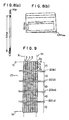
- Figs.9 and 10 show another embodiment of an optical recording card according to the invention, wherein a data truck 2b is shown.
- the data truck 2b is constructed of a Y1 to Y n rows and X1 to X n columns.
- a number of pits 3 arranged in columns constitute a number of pit columns 5.
- a plurality of pit columns 5 (in case of Fig.9, seven data pit columns) are arranged in rows to constitute a data pit group 10.
- a plurality of data pit groups 10 are arranged in columns.
- a division signal pit 20 is positioned between adjacent data pit columns, the division signal pit 20 indicating the boundary between data pit groups 10.
- the division signal pit 20 may be constructed of special data pits.
- a guide bar representative of photo signals as in the case of a data pit is used as the division signal pit 20.
- Guide bars k,l,m and o separate adjacent data pit groups in the column direction and guide the movement of a card.
- discriminator pits 3a and 3b are formed.
- the discriminator pits 3a and 3b are the pits indicating the start and end of each data pit column and have predesignated information.
- the length of a data pit column 5 is l and the width of a pit 3 is b which are set to have proper
- a line sensor 6 for reading pits 3 has a plurality of optical reading elements 7 aligned densely on a straight line.
- the line sensor 6 is disposed at a predetermined position as shown in Fig.10. While the optical recording card 1 is guided by guide bars k, l, m and o and moved to the position of the line sensor 6, the data truck 2b comes to the line sensor 6. Then, the line sensor 6 reads pits 3 of each data pit column.
- the line sensor 6 is connected via a binarization circuit 8, a data compression unit 11, and a memory selector 12, to data processing memories 21 (211 to 21 n ).
- the data processed by the data processing memories 211 to 21 n are combined at a data coupling unit 22.
- the binarization circuit 8 compares signals read from the line sensor 6 in synchro with clock signals with a threshold level to obtain signals from data pits 3.
- the data compression unit 11 compresses a plurality of signals into one signal.
- the line sensor 6 is shifted finely relative to the card to scan the data truck 102.
- the line sensor 6 may ride on several pit columns 5 during one scan, as described previously.
- the line sensor 6 rides on data pit columns 5 f,1 , 5 f,2 , 5 f,3 , 5 e,3 , 5 e,4 and 5 e,5 .
- Information sensed by the line sensor is binarized by the binarization circuit 8 and data-compressed by the data compression unit 11. Simultaneously therewith, it is confirmed if the data in each column has been correctly read using the discriminator pits at both ends of the pit column. The readout data of each column is sent to the memory selector 12.
- the compressed data is serial/parallel converted and stored in th data processing memories 211 to 21 n , processed and combined by the data coupling unit 22 to be sent to the main processor 23.
- the data pit column divided by the memory selector 12 is subjected to data pit compression in the row direction in accordance with discriminator pits. Next, an error detection and correction is performed to complete the readout operation.
- the line sensor 6 is inclined relative to a data pit column 5 and rides on six data pit columns 5 f,1 , 5 f,2 , 5 f,3 , 5 e,3 , 5 e,4 and 5 e,5 . Therefore, during one scan by the line sensor 6, information on the data pit columns 5 f,1 , 5 f,2 , 5 f,3 , 5 e,3 , 5 e,4 and 5 e,5 is mixed. Thus, there is a possibility of erroneously reading the information on another data pit column.
- strobe signals generated by the guide bars k, l, m and o between data pit columns are used while the line sensor 6 is scanning the data truck 2b.
- the readout data is separated and processed.
- the line sensor 6 reads the data pit columns, 5 f,1 , 5 f,2 , 5 f,3 , 5 e,3 , 5 e,4 and 5 e,5 .
- the data pit columns 5 f,1 , 5 f,2 , 5 e,4 and 5 e,5 can be correctly read, and the data pit columns 5 f,3 and 5 e,3 are not correctly read since the line sensor 6 rides on the two pit columns.
- the memory selector 12 is notified by the discriminator pits 3a and 3b that the data pit columns 5 f,3 and 5 e,3 at the third data pit group were not correctly read, to thus make the third pit group data invalid.
- the memory selector 12 separates data for the transmission thereof.
- the data processing memories 211 to 21 n stops immediately the processing and waits for the reception of data. In other cases, i.e., if the memory selector 12 does not access the data processing memories, the former and the latter are completely isolated to perform data processing during such a period.
- each data processing memory 21 it is checked if the effective data read at the previous scan is overlapped upon the present effective data confirmed by an output of the exclusive OR of the discriminator pits. If it is overlapped, it is compressed as a same data. The data is further subjected to an error detection and correction to restore the original data which is temporarily stored. When the stored data becomes more than a necessary data amount, the data coupling unit is notified of such an effect and if it requests, the data is sent out.
- optical recording card with the data truck 2b and the reading method according to the present invention have the following advantages:
- the inclination between a line sensor for reading information written in the card and a data pit column can be corrected without mechanical inclination correction means.
- a reading precision can be retained easily.
- several short data pit columns can be read collectively at a time, thus improving a reading speed.
- a high speed data transfer by a line sensor is not degraded, and the signal processing can be performed in parallel.
- the data of a data bit column at a certain row is arranged to be transferred to a predetermined data processing memory, the data of the upper and lower data pit columns will not be mixed.
- the amount of data to be handled becomes small and the reliability is improved.
- the development cost can be reduced because the same signal processing can be used for all the columns.
Landscapes
- Physics & Mathematics (AREA)
- Engineering & Computer Science (AREA)
- General Physics & Mathematics (AREA)
- Theoretical Computer Science (AREA)
- Health & Medical Sciences (AREA)
- Electromagnetism (AREA)
- General Health & Medical Sciences (AREA)
- Toxicology (AREA)
- Artificial Intelligence (AREA)
- Computer Vision & Pattern Recognition (AREA)
- Optical Recording Or Reproduction (AREA)
- Signal Processing For Digital Recording And Reproducing (AREA)
Priority Applications (1)
| Application Number | Priority Date | Filing Date | Title |
|---|---|---|---|
| AT87307018T ATE99815T1 (de) | 1986-08-09 | 1987-08-07 | Optische aufzeichnungskarte und lesemethode. |
Applications Claiming Priority (4)
| Application Number | Priority Date | Filing Date | Title |
|---|---|---|---|
| JP187475/86 | 1986-08-09 | ||
| JP61187475A JPS6344333A (ja) | 1986-08-09 | 1986-08-09 | 光学記録再生カ−ド |
| JP61250460A JPS63104222A (ja) | 1986-10-21 | 1986-10-21 | 光記録カードの読取り方法 |
| JP250460/86 | 1986-10-21 |
Publications (3)
| Publication Number | Publication Date |
|---|---|
| EP0256807A2 true EP0256807A2 (de) | 1988-02-24 |
| EP0256807A3 EP0256807A3 (en) | 1989-04-26 |
| EP0256807B1 EP0256807B1 (de) | 1994-01-05 |
Family
ID=26504367
Family Applications (1)
| Application Number | Title | Priority Date | Filing Date |
|---|---|---|---|
| EP87307018A Expired - Lifetime EP0256807B1 (de) | 1986-08-09 | 1987-08-07 | Optische Aufzeichnungskarte und Lesemethode |
Country Status (4)
| Country | Link |
|---|---|
| US (1) | US4860275A (de) |
| EP (1) | EP0256807B1 (de) |
| CA (1) | CA1298652C (de) |
| DE (1) | DE3788688T2 (de) |
Cited By (1)
| Publication number | Priority date | Publication date | Assignee | Title |
|---|---|---|---|---|
| WO2007049212A3 (en) * | 2005-10-27 | 2007-09-13 | Koninkl Philips Electronics Nv | System for scanning an information carrier with a plurality of light spots |
Families Citing this family (22)
| Publication number | Priority date | Publication date | Assignee | Title |
|---|---|---|---|---|
| US5280160A (en) * | 1987-02-27 | 1994-01-18 | Canon Kabushiki Kaisha | Recording and reproducing method and apparatus compensating for predicted deviation based on detected relative skewing of recording medium |
| JP2649231B2 (ja) * | 1987-11-20 | 1997-09-03 | 株式会社 日本コンラックス | 光学的情報再生装置 |
| GB8815490D0 (en) * | 1988-06-29 | 1988-08-03 | Key Strip Ltd | Swipe reader |
| JPH02105333A (ja) * | 1988-10-14 | 1990-04-17 | Hitachi Ltd | 光記録シートならびにその再生方法および再生装置 |
| JPH0415774A (ja) * | 1990-05-02 | 1992-01-21 | Eastman Kodak Japan Kk | バーコードリーダ |
| US5132522A (en) * | 1991-01-30 | 1992-07-21 | Olympus Optical Co., Ltd. | Information-reading method |
| US8131570B2 (en) * | 1998-03-10 | 2012-03-06 | Discovery Holdings Limited | Managing the business of a medical insurance plan |
| US8359208B2 (en) | 1999-03-09 | 2013-01-22 | Discover Holdings Limited | Wellness program management and integration with payroll vendor systems |
| US8306899B2 (en) | 2000-08-07 | 2012-11-06 | Discovery Life Ltd. | Managing a life insurance investment |
| GB2369778A (en) | 2000-09-06 | 2002-06-12 | Discovery Health Ltd | Incentivising compliance in members of a disease management programme |
| US7908156B2 (en) | 2002-09-20 | 2011-03-15 | Discovery Holdings Limited | Method of calculating a premium payable by an insured person on a life insurance policy |
| WO2006003537A2 (en) * | 2004-06-28 | 2006-01-12 | Koninklijke Philips Electronics N.V. | Apparatus for reading an information carrier |
| CN101027689A (zh) | 2004-07-26 | 2007-08-29 | 发现控股有限公司 | 用于精确计算医疗保险计划中投保人的折扣的数据处理系统及其方法 |
| WO2007141695A2 (en) | 2006-06-07 | 2007-12-13 | Discovery Holdings Limited | A system and method of managing an insurance scheme |
| CN101553839A (zh) * | 2006-06-07 | 2009-10-07 | 发现控股有限公司 | 管理人寿保险计划的方法及系统 |
| ZA200901041B (en) * | 2006-09-18 | 2010-05-26 | Discovery Holdings Ltd | A method of managing the wellness of an organisation and a system therefor |
| WO2009147592A1 (en) | 2008-06-03 | 2009-12-10 | Discovery Holdings Limited | A system and method of managing an insurance scheme |
| WO2009147591A2 (en) | 2008-06-03 | 2009-12-10 | Discovery Holdings Limited | A system and method of managing an insurance scheme |
| CN102057392A (zh) | 2008-06-03 | 2011-05-11 | 发现控股有限公司 | 管理保险方案的系统和方法 |
| CN101847243A (zh) | 2009-03-11 | 2010-09-29 | 发现控股有限公司 | 运作保险方案以保障个人业绩奖金的系统 |
| KR20120093316A (ko) * | 2009-10-26 | 2012-08-22 | 디스커버리 라이프 리미티드 | 보험 설계를 관리하는 시스템 및 방법 |
| ZA201308624B (en) | 2012-12-21 | 2015-02-25 | Destiny Health Inc | A method of determining the attendance of an individual at a location and a system therefor |
Family Cites Families (3)
| Publication number | Priority date | Publication date | Assignee | Title |
|---|---|---|---|---|
| DE2833908C2 (de) * | 1978-08-02 | 1982-05-06 | Computer Gesellschaft Konstanz Mbh, 7750 Konstanz | Verfahren und Einrichtung zum automatischen Erkennen von Markierungen |
| US4588882A (en) * | 1984-06-06 | 1986-05-13 | Drexler Technology Corporation | Skew detection system for optically read data |
| US4782221A (en) * | 1985-04-01 | 1988-11-01 | Cauzin Systems, Incorporated | Printed data strip including bit-encoded information and scanner control |
-
1987
- 1987-08-05 US US07/082,820 patent/US4860275A/en not_active Expired - Lifetime
- 1987-08-07 EP EP87307018A patent/EP0256807B1/de not_active Expired - Lifetime
- 1987-08-07 CA CA000543974A patent/CA1298652C/en not_active Expired - Lifetime
- 1987-08-07 DE DE87307018T patent/DE3788688T2/de not_active Expired - Fee Related
Cited By (1)
| Publication number | Priority date | Publication date | Assignee | Title |
|---|---|---|---|---|
| WO2007049212A3 (en) * | 2005-10-27 | 2007-09-13 | Koninkl Philips Electronics Nv | System for scanning an information carrier with a plurality of light spots |
Also Published As
| Publication number | Publication date |
|---|---|
| EP0256807B1 (de) | 1994-01-05 |
| DE3788688T2 (de) | 1994-04-28 |
| CA1298652C (en) | 1992-04-07 |
| US4860275A (en) | 1989-08-22 |
| DE3788688D1 (de) | 1994-02-17 |
| EP0256807A3 (en) | 1989-04-26 |
Similar Documents
| Publication | Publication Date | Title |
|---|---|---|
| EP0256807B1 (de) | Optische Aufzeichnungskarte und Lesemethode | |
| US5343031A (en) | Method of decoding a two-dimensional code symbol mark | |
| US4634850A (en) | Quad density optical data system | |
| US7175088B2 (en) | Two-dimensional code having superior decoding property which is possible to control the level of error correcting codes, and method for encoding and decoding the same | |
| JP2881306B2 (ja) | 透過的読出高密度光学データシステム | |
| US4734565A (en) | Read-only optical card and system | |
| US5442164A (en) | Bar code reader for reading two-dimensional bar codes by using length information derived from a sensed signal | |
| EP0160008B1 (de) | Optisches datensystem mit vierfachdichte | |
| EP0085749B1 (de) | Maschinell lesbare Aufzeichnung | |
| US6097875A (en) | Information reproducing apparatus for optically reading a data code pattern from an information recording medium where information is recorded as an optically readable data code pattern, and for reproducing such information | |
| US5051569A (en) | Method for recording data onto optical data recording cards including data regions and sync regions | |
| KR920006772B1 (ko) | 매체정보 판독인자장치 및 방법 | |
| JP2515282B2 (ja) | 光デ―タ記録カ―ド | |
| JP2002259902A (ja) | データ記録媒体及びコード読取装置 | |
| JPH0555931B2 (de) | ||
| JPH0359489B2 (de) | ||
| JPS6151627A (ja) | 光メモリカ−ド読出し装置 | |
| JPS6220033Y2 (de) | ||
| JP2619915B2 (ja) | 情報処理方法および装置 | |
| JPH0430648B2 (de) | ||
| JPS62205530A (ja) | 光カ−ドの読取装置 | |
| JPS5914080A (ja) | スキユ−検出方式 | |
| JPS62145590A (ja) | 光デジタルデ−タの記録方法 | |
| JPH0685219B2 (ja) | 光デジタルデータの読取り制御方法 | |
| JPH0214391A (ja) | 異種カードのデータ読取方法 |
Legal Events
| Date | Code | Title | Description |
|---|---|---|---|
| PUAI | Public reference made under article 153(3) epc to a published international application that has entered the european phase |
Free format text: ORIGINAL CODE: 0009012 |
|
| 17P | Request for examination filed |
Effective date: 19870820 |
|
| AK | Designated contracting states |
Kind code of ref document: A2 Designated state(s): AT BE CH DE FR GB IT LI NL SE |
|
| PUAL | Search report despatched |
Free format text: ORIGINAL CODE: 0009013 |
|
| AK | Designated contracting states |
Kind code of ref document: A3 Designated state(s): AT BE CH DE FR GB IT LI NL SE |
|
| RHK1 | Main classification (correction) |
Ipc: G06K 7/015 |
|
| 17Q | First examination report despatched |
Effective date: 19911125 |
|
| GRAA | (expected) grant |
Free format text: ORIGINAL CODE: 0009210 |
|
| AK | Designated contracting states |
Kind code of ref document: B1 Designated state(s): AT BE CH DE FR GB IT LI NL SE |
|
| REF | Corresponds to: |
Ref document number: 99815 Country of ref document: AT Date of ref document: 19940115 Kind code of ref document: T |
|
| REF | Corresponds to: |
Ref document number: 3788688 Country of ref document: DE Date of ref document: 19940217 |
|
| ITF | It: translation for a ep patent filed | ||
| ET | Fr: translation filed | ||
| PLBE | No opposition filed within time limit |
Free format text: ORIGINAL CODE: 0009261 |
|
| STAA | Information on the status of an ep patent application or granted ep patent |
Free format text: STATUS: NO OPPOSITION FILED WITHIN TIME LIMIT |
|
| 26N | No opposition filed | ||
| EAL | Se: european patent in force in sweden |
Ref document number: 87307018.9 |
|
| PGFP | Annual fee paid to national office [announced via postgrant information from national office to epo] |
Ref country code: GB Payment date: 19990121 Year of fee payment: 12 |
|
| PGFP | Annual fee paid to national office [announced via postgrant information from national office to epo] |
Ref country code: DE Payment date: 19990125 Year of fee payment: 12 |
|
| PGFP | Annual fee paid to national office [announced via postgrant information from national office to epo] |
Ref country code: SE Payment date: 19990126 Year of fee payment: 12 Ref country code: FR Payment date: 19990126 Year of fee payment: 12 |
|
| PGFP | Annual fee paid to national office [announced via postgrant information from national office to epo] |
Ref country code: AT Payment date: 19990127 Year of fee payment: 12 |
|
| PGFP | Annual fee paid to national office [announced via postgrant information from national office to epo] |
Ref country code: NL Payment date: 19990131 Year of fee payment: 12 |
|
| PGFP | Annual fee paid to national office [announced via postgrant information from national office to epo] |
Ref country code: CH Payment date: 19990210 Year of fee payment: 12 |
|
| PGFP | Annual fee paid to national office [announced via postgrant information from national office to epo] |
Ref country code: BE Payment date: 19990215 Year of fee payment: 12 |
|
| PG25 | Lapsed in a contracting state [announced via postgrant information from national office to epo] |
Ref country code: GB Free format text: LAPSE BECAUSE OF NON-PAYMENT OF DUE FEES Effective date: 19990807 |
|
| PG25 | Lapsed in a contracting state [announced via postgrant information from national office to epo] |
Ref country code: AT Free format text: LAPSE BECAUSE OF NON-PAYMENT OF DUE FEES Effective date: 19990808 |
|
| PG25 | Lapsed in a contracting state [announced via postgrant information from national office to epo] |
Ref country code: SE Free format text: THE PATENT HAS BEEN ANNULLED BY A DECISION OF A NATIONAL AUTHORITY Effective date: 19990830 |
|
| PG25 | Lapsed in a contracting state [announced via postgrant information from national office to epo] |
Ref country code: LI Free format text: LAPSE BECAUSE OF NON-PAYMENT OF DUE FEES Effective date: 19990831 Ref country code: CH Free format text: LAPSE BECAUSE OF NON-PAYMENT OF DUE FEES Effective date: 19990831 Ref country code: BE Free format text: LAPSE BECAUSE OF NON-PAYMENT OF DUE FEES Effective date: 19990831 |
|
| BERE | Be: lapsed |
Owner name: KYODO PRINTING CO. LTD Effective date: 19990831 |
|
| PG25 | Lapsed in a contracting state [announced via postgrant information from national office to epo] |
Ref country code: NL Free format text: LAPSE BECAUSE OF NON-PAYMENT OF DUE FEES Effective date: 20000301 |
|
| GBPC | Gb: european patent ceased through non-payment of renewal fee |
Effective date: 19990807 |
|
| REG | Reference to a national code |
Ref country code: CH Ref legal event code: PL |
|
| PG25 | Lapsed in a contracting state [announced via postgrant information from national office to epo] |
Ref country code: FR Free format text: LAPSE BECAUSE OF NON-PAYMENT OF DUE FEES Effective date: 20000428 |
|
| EUG | Se: european patent has lapsed |
Ref document number: 87307018.9 |
|
| NLV4 | Nl: lapsed or anulled due to non-payment of the annual fee |
Effective date: 20000301 |
|
| PG25 | Lapsed in a contracting state [announced via postgrant information from national office to epo] |
Ref country code: DE Free format text: LAPSE BECAUSE OF NON-PAYMENT OF DUE FEES Effective date: 20000601 |
|
| REG | Reference to a national code |
Ref country code: FR Ref legal event code: ST |
|
| PG25 | Lapsed in a contracting state [announced via postgrant information from national office to epo] |
Ref country code: IT Free format text: LAPSE BECAUSE OF NON-PAYMENT OF DUE FEES;WARNING: LAPSES OF ITALIAN PATENTS WITH EFFECTIVE DATE BEFORE 2007 MAY HAVE OCCURRED AT ANY TIME BEFORE 2007. THE CORRECT EFFECTIVE DATE MAY BE DIFFERENT FROM THE ONE RECORDED. Effective date: 20050807 |
|
| APAH | Appeal reference modified |
Free format text: ORIGINAL CODE: EPIDOSCREFNO |