EP0256991A2 - Dispositif de transfert et de retournement simultanés d'objets - Google Patents
Dispositif de transfert et de retournement simultanés d'objets Download PDFInfo
- Publication number
- EP0256991A2 EP0256991A2 EP87830140A EP87830140A EP0256991A2 EP 0256991 A2 EP0256991 A2 EP 0256991A2 EP 87830140 A EP87830140 A EP 87830140A EP 87830140 A EP87830140 A EP 87830140A EP 0256991 A2 EP0256991 A2 EP 0256991A2
- Authority
- EP
- European Patent Office
- Prior art keywords
- articles
- positions
- cylindrical body
- grooves
- article
- Prior art date
- Legal status (The legal status is an assumption and is not a legal conclusion. Google has not performed a legal analysis and makes no representation as to the accuracy of the status listed.)
- Granted
Links
Images

Classifications
-
- B—PERFORMING OPERATIONS; TRANSPORTING
- B65—CONVEYING; PACKING; STORING; HANDLING THIN OR FILAMENTARY MATERIAL
- B65G—TRANSPORT OR STORAGE DEVICES, e.g. CONVEYORS FOR LOADING OR TIPPING, SHOP CONVEYOR SYSTEMS OR PNEUMATIC TUBE CONVEYORS
- B65G47/00—Article or material-handling devices associated with conveyors; Methods employing such devices
- B65G47/22—Devices influencing the relative position or the attitude of articles during transit by conveyors
- B65G47/24—Devices influencing the relative position or the attitude of articles during transit by conveyors orientating the articles
- B65G47/248—Devices influencing the relative position or the attitude of articles during transit by conveyors orientating the articles by turning over or inverting them
- B65G47/252—Devices influencing the relative position or the attitude of articles during transit by conveyors orientating the articles by turning over or inverting them about an axis substantially perpendicular to the conveying direction
Definitions
- the present invention is directed to a device for transferring and tilting articles, in particular of smaLL size', possibly for being processed on two opposite faces.
- the technique does not offer at present any efficient means but simple pushers, such as when feeding pieces in the minting of coins, and in practice it is impossible to transfer and tiLt in a quick sequence small items, especially if the smaLL size is shown by the side provided for their clamping.
- this side is also shaped so as to render difficult its taking, when it is for example with tapered waLLs, magneticaLLy or vacuum-actuated equipments for Lifting articles would be in practice useless, since sideLy clamping devices would be however necessary for the tilting action.
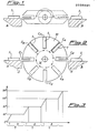
- a solution such as represented diagrammaticaLLy on Fig. 1 of the drawings could be provided, wherein an arm is formed with a recess for housing a piece 1 being pushed by a known means, and thereafter, upon a rotation of 180°, reaches the position shown in phantom Lines thus allowing piece 1 to be positioned in B, upon another operation of known pushing means.
- a solution is not satisfactory for its inherent slowness, due to the unavoidable idle time periods during which the arm carries out these rotations of 180°.
- the object of the present invention is to provide an apparatus which does not show the above-mentioned drawbacks by performing the transfer and contemporaneous tilting of the articles in such a manner not to cause idle time periods and bottleneck chokes in a high-speed automatic Line.
- the above-mentioned cylindrical body is operated by actuating means to carry out in sequence elementary rotations of a 360°:n angle, where n is the provided number of grooves on the body itself, each elementary rotation being separated from the subsequent one by a stop stage of the body itself, during which an article is pushed into a groove from said first position and at the same time another article is discharged from the diametraLLy opposite groove towards said second position.
- n is the provided number of grooves on the body itself
- each elementary rotation being separated from the subsequent one by a stop stage of the body itself, during which an article is pushed into a groove from said first position and at the same time another article is discharged from the diametraLLy opposite groove towards said second position.
- Each one of these grooves can aLso have means for holding the article during rotation of the cyLindricaL body.
- said first and second positions are both provided on one mobile, continuous supporting surface which in a first instance is made of a Linear conveyor and in a second instance corresponds to a single turntable with the said cylindrical body being mounted next to said surface, having a diametral plane thereof flush with the Latter and at a minimum distance therefrom, said grooves being charged and discharged in a direction paraLLeL to the axis of said cyLindricaL body.
- the article to be transferred and tilted designated 1
- the first, starting position of article 1 is always indicated as A, and the second, receiving or final position is indicated as B.
- the possible embodiment with rotating arm, shown in Fig. 1 and not being part of the present invention has already been discussed above.
- FIG. 2 wherein an article 1 has to be transferred and at the same time tilted from position A to position B, between these two positions there is mounted the rotation axis X of a cylindrical body 10 the diameter of which covers substantially almost the whole minimum distance between said two positions A and B, except for a smaLL clearance.
- a plurality of radiaL grooves here in number of eight, C 1 -C 8 equaLLy spaced along the periphery of body 10, each of them being arranged to receive one of said articles 1. According to the direction of arrows considered in Fig.
- the article is pushed from the position A by a means weLL-known in the art into the groove C 1 being at that moment flush with such a position.
- the cylindrical body 10 rotates as it is mounted on the axis of an actuator (not shown), so as to accomplish each time a rotation of 360°/n, if n is the number of grooves C 1 -C n .
- the article 1 intiaLLy positioned in C 1 will assume the position initially occupied by C 5 upon a total rotation of 180°, and therefrom it will be pushed to the position B by a similar known means.
- positions A, B are respectively the mutually nearest peripheral zones of a first and a second turntable 3, 5 of a grinding machine (not shown).
- the transfer of the piece from a table to the other in practice occurs at the same time and with the shortest delay required therefor without the necessity of additionaL time for each rotation from position A to B.
- the only idle time period is provided during the first 180° rotation, until the n/2 grooves of a half cylinder are Loaded, whereas with the solution of Fig. 1 this idle time period would be repeated during the whole operation.
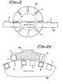
- the cylindrical body 10' still has a number of radiaL grooves C which will be open sidely to allow Loading and unloading of the articles 1 therefrom in a direction that is no Longer radiaL as in Fig. 2, but parallel to the rotation axis X of the body 10', as it is clearly shown in the plan view of Fig. 4a.
- the distance between two diametrally opposite grooves which is again substantially the same as the distance between the positions A-B, will also correspond to the distance between the positions on the mobile support 11 occupied by two non successive articles 1 having an even number of said articles therebetween.
- the article taken at A upon a rotation of 180° for its tiLting is caused to rest again on the support 11 at B being upstream of the initial position, as seen according to the arrow indicating the forward or feed direction of the conveyor 11, along which the tiLted articLe moves again. It is Like as on the conveyor 11 two alternate series of articles 1 were positioned which show opposite faces free upwards.
- the use of the device according to the invention is not meant to'be restricted to articles of smaLL size, as it can be generaLLy used with items to be transferred and tilted irrespective of their size.
- each groove C could be provided with clamping means to hold article 1 during rotation, such a means being for exampLe provided by a suitable shape of the groove or a real clamping means, such as of the spring type.
Landscapes
- Engineering & Computer Science (AREA)
- Mechanical Engineering (AREA)
- Specific Conveyance Elements (AREA)
Applications Claiming Priority (2)
| Application Number | Priority Date | Filing Date | Title |
|---|---|---|---|
| IT20056/86A IT1190620B (it) | 1986-04-11 | 1986-04-11 | Dispositivo per il trasferimento e contemporaneo ribaltamento di articoli |
| IT2005686 | 1986-04-11 |
Publications (3)
| Publication Number | Publication Date |
|---|---|
| EP0256991A2 true EP0256991A2 (fr) | 1988-02-24 |
| EP0256991A3 EP0256991A3 (en) | 1988-11-02 |
| EP0256991B1 EP0256991B1 (fr) | 1991-10-09 |
Family
ID=11163458
Family Applications (1)
| Application Number | Title | Priority Date | Filing Date |
|---|---|---|---|
| EP87830140A Expired EP0256991B1 (fr) | 1986-04-11 | 1987-04-10 | Dispositif de transfert et de retournement simultanés d'objets |
Country Status (3)
| Country | Link |
|---|---|
| EP (1) | EP0256991B1 (fr) |
| DE (1) | DE3773585D1 (fr) |
| IT (1) | IT1190620B (fr) |
Cited By (13)
| Publication number | Priority date | Publication date | Assignee | Title |
|---|---|---|---|---|
| EP0392584A1 (fr) * | 1989-04-10 | 1990-10-17 | WERNER & PFLEIDERER-HATON B.V. | Appareil pour retourner une feuille de pâte qui quitte deux rouleaux |
| EP0492950A1 (fr) * | 1990-12-21 | 1992-07-01 | Fabriques De Tabac Reunies S.A. | Procédé pour le collage de paquets d'articles pour fumeurs |
| DE4112435A1 (de) * | 1991-04-16 | 1992-12-24 | Schlafhorst & Co W | Kopslieferstation |
| GB2266046A (en) * | 1989-08-12 | 1993-10-20 | Food Machinery Design Ltd | Article orientator |
| GB2234668B (en) * | 1989-08-12 | 1994-02-16 | Food Machinery Design Ltd | Machines for cutting soft or semi-soft materials |
| DE19527264A1 (de) * | 1995-07-26 | 1997-01-30 | Heidelberger Druckmasch Ag | Druckmaschine mit geradliniger Substratführung und Wendeeinrichtungen dafür |
| DE10116481A1 (de) * | 2001-04-03 | 2002-10-10 | Hans Walter Mohr Gmbh | Vorrichtung zum Wenden |
| ES2258413A1 (es) * | 2006-02-10 | 2006-08-16 | Tecnicas De Automatizacion De Canteras Salas, S.L.L. | Aparato volteador de laminas de materiales petreos. |
| CN103287834A (zh) * | 2012-03-02 | 2013-09-11 | 广东科达机电股份有限公司 | 一种可选翻面装置 |
| CN103407772A (zh) * | 2013-08-12 | 2013-11-27 | 苏州市盛百威包装设备有限公司 | 一种用于翻转纸盒的翻转进料机构 |
| CN103693402A (zh) * | 2012-09-27 | 2014-04-02 | 昆山瀚崴自动化设备有限公司 | 一种翻板机 |
| CN109483651A (zh) * | 2018-11-20 | 2019-03-19 | 郑俊英 | 一种家具用木条多角度翻转定位设备 |
| CN111977336A (zh) * | 2019-05-24 | 2020-11-24 | 赤壁市万皇智能设备有限公司 | 一种用于pcb双面板印刷线的翻板机构 |
Family Cites Families (2)
| Publication number | Priority date | Publication date | Assignee | Title |
|---|---|---|---|---|
| BE626938A (fr) * | 1963-01-25 | |||
| DD244321B1 (de) * | 1985-12-19 | 1990-08-08 | Nagema Veb K | Vorrichtung zum wenden von dauebackwaren |
-
1986
- 1986-04-11 IT IT20056/86A patent/IT1190620B/it active
-
1987
- 1987-04-10 EP EP87830140A patent/EP0256991B1/fr not_active Expired
- 1987-04-10 DE DE8787830140T patent/DE3773585D1/de not_active Expired - Fee Related
Cited By (18)
| Publication number | Priority date | Publication date | Assignee | Title |
|---|---|---|---|---|
| EP0392584A1 (fr) * | 1989-04-10 | 1990-10-17 | WERNER & PFLEIDERER-HATON B.V. | Appareil pour retourner une feuille de pâte qui quitte deux rouleaux |
| GB2234668B (en) * | 1989-08-12 | 1994-02-16 | Food Machinery Design Ltd | Machines for cutting soft or semi-soft materials |
| GB2266046A (en) * | 1989-08-12 | 1993-10-20 | Food Machinery Design Ltd | Article orientator |
| GB2266046B (en) * | 1989-08-12 | 1994-02-02 | Food Machinery Design Ltd | Article orientation |
| EP0492950A1 (fr) * | 1990-12-21 | 1992-07-01 | Fabriques De Tabac Reunies S.A. | Procédé pour le collage de paquets d'articles pour fumeurs |
| DE4112435C2 (de) * | 1991-04-16 | 2000-07-06 | Schlafhorst & Co W | Kopslieferstation |
| DE4112435A1 (de) * | 1991-04-16 | 1992-12-24 | Schlafhorst & Co W | Kopslieferstation |
| DE19527264A1 (de) * | 1995-07-26 | 1997-01-30 | Heidelberger Druckmasch Ag | Druckmaschine mit geradliniger Substratführung und Wendeeinrichtungen dafür |
| US5732623A (en) * | 1995-07-26 | 1998-03-31 | Heidelberger Druckmaschinen Ag | Printing press with rectilinear substrate transport and turning devices therefor |
| DE10116481A1 (de) * | 2001-04-03 | 2002-10-10 | Hans Walter Mohr Gmbh | Vorrichtung zum Wenden |
| ES2258413A1 (es) * | 2006-02-10 | 2006-08-16 | Tecnicas De Automatizacion De Canteras Salas, S.L.L. | Aparato volteador de laminas de materiales petreos. |
| ES2258413B1 (es) * | 2006-02-10 | 2007-11-16 | Tecnicas De Automatizacion De Canteras Salas, S.L.L. | Aparato volteador de laminas de materiales petreos. |
| CN103287834A (zh) * | 2012-03-02 | 2013-09-11 | 广东科达机电股份有限公司 | 一种可选翻面装置 |
| CN103693402A (zh) * | 2012-09-27 | 2014-04-02 | 昆山瀚崴自动化设备有限公司 | 一种翻板机 |
| CN103407772A (zh) * | 2013-08-12 | 2013-11-27 | 苏州市盛百威包装设备有限公司 | 一种用于翻转纸盒的翻转进料机构 |
| CN109483651A (zh) * | 2018-11-20 | 2019-03-19 | 郑俊英 | 一种家具用木条多角度翻转定位设备 |
| CN109483651B (zh) * | 2018-11-20 | 2021-05-25 | 郑俊英 | 一种家具用木条多角度翻转定位设备 |
| CN111977336A (zh) * | 2019-05-24 | 2020-11-24 | 赤壁市万皇智能设备有限公司 | 一种用于pcb双面板印刷线的翻板机构 |
Also Published As
| Publication number | Publication date |
|---|---|
| IT8620056A1 (it) | 1987-10-11 |
| EP0256991B1 (fr) | 1991-10-09 |
| IT8620056A0 (it) | 1986-04-11 |
| EP0256991A3 (en) | 1988-11-02 |
| IT1190620B (it) | 1988-02-16 |
| DE3773585D1 (de) | 1991-11-14 |
Similar Documents
| Publication | Publication Date | Title |
|---|---|---|
| EP0256991A2 (fr) | Dispositif de transfert et de retournement simultanés d'objets | |
| US5407314A (en) | Apparatus for synchronizing loading and unloading of substrates with turntable movement in a coating chamber | |
| US3306442A (en) | Multi-program apparatus | |
| US5065499A (en) | Apparatus for making electric motor parts employing pallet with removable workpiece holder | |
| US5377815A (en) | Conveyor apparatus for batch treatment of objects | |
| US4325125A (en) | Apparatus for orienting out-of-round workpieces | |
| JP2001038615A5 (fr) | ||
| US5240235A (en) | Apparatus for making electric motor parts employing pallet with removable workpiece holder | |
| GB1385076A (en) | Apparatus for loading and unloading an automatic machine tool | |
| CN114929433B (zh) | 搬运装置 | |
| US3999645A (en) | Work handling apparatus | |
| JPS5840262A (ja) | 加工物の表面仕上げ装置 | |
| US6086728A (en) | Cross flow metalizing of compact discs | |
| US3565232A (en) | Article feeding mechanism | |
| JPH03149153A (ja) | 自動パレット交換装置 | |
| GB2364661A (en) | Rotating table transfer machine | |
| US4865509A (en) | Walking beam gripper | |
| EP0374489A3 (fr) | Méthode et dispositif pour la fabrication de supports cylindriques dans des dispositifs à rogner | |
| JPH02122541A (ja) | 半導体ウェーハの移載装置 | |
| SU1404259A1 (ru) | Устройство дл ориентированной подачи деталей | |
| SU1745513A1 (ru) | Устройство дл подачи деталей | |
| KR930017659A (ko) | Nc 선반의 무인 연속가공 시스템 | |
| JPH04372364A (ja) | 両面加工機 | |
| JPH04148718A (ja) | ワーク反転装置 | |
| SU908575A1 (ru) | Многопозиционный станок |
Legal Events
| Date | Code | Title | Description |
|---|---|---|---|
| PUAI | Public reference made under article 153(3) epc to a published international application that has entered the european phase |
Free format text: ORIGINAL CODE: 0009012 |
|
| AK | Designated contracting states |
Kind code of ref document: A2 Designated state(s): CH DE FR GB LI |
|
| PUAL | Search report despatched |
Free format text: ORIGINAL CODE: 0009013 |
|
| AK | Designated contracting states |
Kind code of ref document: A3 Designated state(s): CH DE FR GB LI |
|
| 17P | Request for examination filed |
Effective date: 19890408 |
|
| 17Q | First examination report despatched |
Effective date: 19900813 |
|
| GRAA | (expected) grant |
Free format text: ORIGINAL CODE: 0009210 |
|
| AK | Designated contracting states |
Kind code of ref document: B1 Designated state(s): CH DE FR GB LI |
|
| REF | Corresponds to: |
Ref document number: 3773585 Country of ref document: DE Date of ref document: 19911114 |
|
| ET | Fr: translation filed | ||
| PGFP | Annual fee paid to national office [announced via postgrant information from national office to epo] |
Ref country code: GB Payment date: 19920320 Year of fee payment: 6 |
|
| PGFP | Annual fee paid to national office [announced via postgrant information from national office to epo] |
Ref country code: CH Payment date: 19920323 Year of fee payment: 6 |
|
| PGFP | Annual fee paid to national office [announced via postgrant information from national office to epo] |
Ref country code: FR Payment date: 19920429 Year of fee payment: 6 |
|
| PGFP | Annual fee paid to national office [announced via postgrant information from national office to epo] |
Ref country code: DE Payment date: 19920527 Year of fee payment: 6 |
|
| PLBE | No opposition filed within time limit |
Free format text: ORIGINAL CODE: 0009261 |
|
| STAA | Information on the status of an ep patent application or granted ep patent |
Free format text: STATUS: NO OPPOSITION FILED WITHIN TIME LIMIT |
|
| 26N | No opposition filed | ||
| PG25 | Lapsed in a contracting state [announced via postgrant information from national office to epo] |
Ref country code: GB Effective date: 19930410 |
|
| PG25 | Lapsed in a contracting state [announced via postgrant information from national office to epo] |
Ref country code: LI Effective date: 19930430 Ref country code: CH Effective date: 19930430 |
|
| GBPC | Gb: european patent ceased through non-payment of renewal fee |
Effective date: 19930410 |
|
| PG25 | Lapsed in a contracting state [announced via postgrant information from national office to epo] |
Ref country code: FR Effective date: 19931229 |
|
| REG | Reference to a national code |
Ref country code: CH Ref legal event code: PL |
|
| PG25 | Lapsed in a contracting state [announced via postgrant information from national office to epo] |
Ref country code: DE Effective date: 19940101 |
|
| REG | Reference to a national code |
Ref country code: FR Ref legal event code: ST |