EP0257013A2 - Verfahren und Vorrichtung zum mechanischen Schleifen und Polieren der Fläche eines mineralischen Materials, insbesondere aus Glas - Google Patents
Verfahren und Vorrichtung zum mechanischen Schleifen und Polieren der Fläche eines mineralischen Materials, insbesondere aus Glas Download PDFInfo
- Publication number
- EP0257013A2 EP0257013A2 EP87870115A EP87870115A EP0257013A2 EP 0257013 A2 EP0257013 A2 EP 0257013A2 EP 87870115 A EP87870115 A EP 87870115A EP 87870115 A EP87870115 A EP 87870115A EP 0257013 A2 EP0257013 A2 EP 0257013A2
- Authority
- EP
- European Patent Office
- Prior art keywords
- axis
- grinding wheel
- rotation
- strip
- polishing
- Prior art date
- Legal status (The legal status is an assumption and is not a legal conclusion. Google has not performed a legal analysis and makes no representation as to the accuracy of the status listed.)
- Granted
Links
- 238000000227 grinding Methods 0.000 title claims abstract description 87
- 238000005498 polishing Methods 0.000 title claims abstract description 45
- 238000000034 method Methods 0.000 title claims description 51
- 239000000463 material Substances 0.000 title claims description 14
- 229910052500 inorganic mineral Inorganic materials 0.000 title claims description 6
- 239000011707 mineral Substances 0.000 title claims description 6
- 239000011521 glass Substances 0.000 title abstract description 31
- 239000003082 abrasive agent Substances 0.000 claims abstract description 19
- 229910003460 diamond Inorganic materials 0.000 claims description 43
- 239000010432 diamond Substances 0.000 claims description 43
- 229910000420 cerium oxide Inorganic materials 0.000 claims description 5
- 238000010438 heat treatment Methods 0.000 claims description 5
- BMMGVYCKOGBVEV-UHFFFAOYSA-N oxo(oxoceriooxy)cerium Chemical compound [Ce]=O.O=[Ce]=O BMMGVYCKOGBVEV-UHFFFAOYSA-N 0.000 claims description 5
- 239000000725 suspension Substances 0.000 claims description 3
- 239000002253 acid Substances 0.000 description 14
- 239000013078 crystal Substances 0.000 description 10
- 241001639412 Verres Species 0.000 description 6
- 229910010293 ceramic material Inorganic materials 0.000 description 5
- 238000005520 cutting process Methods 0.000 description 5
- 239000000243 solution Substances 0.000 description 5
- 238000005299 abrasion Methods 0.000 description 3
- 230000007547 defect Effects 0.000 description 3
- 230000000694 effects Effects 0.000 description 3
- 229920000297 Rayon Polymers 0.000 description 2
- 238000010306 acid treatment Methods 0.000 description 2
- 238000007664 blowing Methods 0.000 description 2
- 238000006073 displacement reaction Methods 0.000 description 2
- 239000012530 fluid Substances 0.000 description 2
- 239000002932 luster Substances 0.000 description 2
- 238000004519 manufacturing process Methods 0.000 description 2
- 229910052751 metal Inorganic materials 0.000 description 2
- 239000002184 metal Substances 0.000 description 2
- 230000003287 optical effect Effects 0.000 description 2
- 238000003825 pressing Methods 0.000 description 2
- 238000000746 purification Methods 0.000 description 2
- 239000002964 rayon Substances 0.000 description 2
- HBMJWWWQQXIZIP-UHFFFAOYSA-N silicon carbide Chemical compound [Si+]#[C-] HBMJWWWQQXIZIP-UHFFFAOYSA-N 0.000 description 2
- 229910010271 silicon carbide Inorganic materials 0.000 description 2
- 241001417495 Serranidae Species 0.000 description 1
- 239000000654 additive Substances 0.000 description 1
- 239000000853 adhesive Substances 0.000 description 1
- 230000001070 adhesive effect Effects 0.000 description 1
- 239000007864 aqueous solution Substances 0.000 description 1
- 239000011230 binding agent Substances 0.000 description 1
- 230000015572 biosynthetic process Effects 0.000 description 1
- 239000000919 ceramic Substances 0.000 description 1
- 238000006243 chemical reaction Methods 0.000 description 1
- 238000004140 cleaning Methods 0.000 description 1
- 239000007799 cork Substances 0.000 description 1
- 229910052593 corundum Inorganic materials 0.000 description 1
- 239000010431 corundum Substances 0.000 description 1
- 238000010586 diagram Methods 0.000 description 1
- 238000004090 dissolution Methods 0.000 description 1
- 230000035622 drinking Effects 0.000 description 1
- 239000013013 elastic material Substances 0.000 description 1
- 230000008030 elimination Effects 0.000 description 1
- 238000003379 elimination reaction Methods 0.000 description 1
- 238000005530 etching Methods 0.000 description 1
- 239000004744 fabric Substances 0.000 description 1
- 239000003517 fume Substances 0.000 description 1
- -1 lead Chemical class 0.000 description 1
- 239000007788 liquid Substances 0.000 description 1
- 230000007774 longterm Effects 0.000 description 1
- 238000012423 maintenance Methods 0.000 description 1
- 150000002739 metals Chemical class 0.000 description 1
- 239000000203 mixture Substances 0.000 description 1
- 238000007517 polishing process Methods 0.000 description 1
- 239000011148 porous material Substances 0.000 description 1
- 230000000750 progressive effect Effects 0.000 description 1
- 239000008262 pumice Substances 0.000 description 1
- 239000011347 resin Substances 0.000 description 1
- 229920005989 resin Polymers 0.000 description 1
- 230000000717 retained effect Effects 0.000 description 1
- 150000003839 salts Chemical class 0.000 description 1
- 239000004575 stone Substances 0.000 description 1
- QAOWNCQODCNURD-UHFFFAOYSA-N sulfuric acid group Chemical class S(O)(O)(=O)=O QAOWNCQODCNURD-UHFFFAOYSA-N 0.000 description 1
- 239000004094 surface-active agent Substances 0.000 description 1
- 238000011144 upstream manufacturing Methods 0.000 description 1
- 231100000925 very toxic Toxicity 0.000 description 1
- 239000002351 wastewater Substances 0.000 description 1
- 239000003643 water by type Substances 0.000 description 1
Images


Classifications
-
- B—PERFORMING OPERATIONS; TRANSPORTING
- B24—GRINDING; POLISHING
- B24B—MACHINES, DEVICES, OR PROCESSES FOR GRINDING OR POLISHING; DRESSING OR CONDITIONING OF ABRADING SURFACES; FEEDING OF GRINDING, POLISHING, OR LAPPING AGENTS
- B24B7/00—Machines or devices designed for grinding plane surfaces on work, including polishing plane glass surfaces; Accessories therefor
- B24B7/20—Machines or devices designed for grinding plane surfaces on work, including polishing plane glass surfaces; Accessories therefor characterised by a special design with respect to properties of the material of non-metallic articles to be ground
- B24B7/22—Machines or devices designed for grinding plane surfaces on work, including polishing plane glass surfaces; Accessories therefor characterised by a special design with respect to properties of the material of non-metallic articles to be ground for grinding inorganic material, e.g. stone, ceramics, porcelain
- B24B7/24—Machines or devices designed for grinding plane surfaces on work, including polishing plane glass surfaces; Accessories therefor characterised by a special design with respect to properties of the material of non-metallic articles to be ground for grinding inorganic material, e.g. stone, ceramics, porcelain for grinding or polishing glass
- B24B7/241—Methods
-
- B—PERFORMING OPERATIONS; TRANSPORTING
- B24—GRINDING; POLISHING
- B24B—MACHINES, DEVICES, OR PROCESSES FOR GRINDING OR POLISHING; DRESSING OR CONDITIONING OF ABRADING SURFACES; FEEDING OF GRINDING, POLISHING, OR LAPPING AGENTS
- B24B19/00—Single-purpose machines or devices for particular grinding operations not covered by any other main group
- B24B19/006—Single-purpose machines or devices for particular grinding operations not covered by any other main group for grinding hollow glassware, bottles
-
- B—PERFORMING OPERATIONS; TRANSPORTING
- B24—GRINDING; POLISHING
- B24B—MACHINES, DEVICES, OR PROCESSES FOR GRINDING OR POLISHING; DRESSING OR CONDITIONING OF ABRADING SURFACES; FEEDING OF GRINDING, POLISHING, OR LAPPING AGENTS
- B24B29/00—Machines or devices for polishing surfaces on work by means of tools made of soft or flexible material with or without the application of solid or liquid polishing agents
- B24B29/02—Machines or devices for polishing surfaces on work by means of tools made of soft or flexible material with or without the application of solid or liquid polishing agents designed for particular workpieces
- B24B29/04—Machines or devices for polishing surfaces on work by means of tools made of soft or flexible material with or without the application of solid or liquid polishing agents designed for particular workpieces for rotationally symmetrical workpieces, e.g. ball-, cylinder- or cone-shaped workpieces
Definitions
- the present invention relates to a method for mechanically polishing a surface of an object made of mineral material using at least one grinding wheel driven in rotation and an abrasive material, possibly in several stages, in which this is driven. surface in rotation about an axis of symmetry, by putting it in contact with the abovementioned grinding wheel (s) under an appropriate and constant application pressure for the duration of grinding and / or polishing, so as to sweep this surface and achieve a well defined depth of pass.
- the method according to the present invention is a method for mechanically polishing a flat or curved surface of an object made of glass, crystal or ceramic material such as a drinking glass, a vase, an ashtray or any other object made of mineral material with a flat surface or a radius of curvature from 150 mm to 1 m.
- This known method has the drawback of showing marks or streaks on the treated surface. To eliminate these streaks, the treated surface must be subjected to a manual sanding treatment, for example using a lapping machine.
- a method is also known for polishing or softening a flat surface of a glass object in which heavy complex machines are used in which a cup wheel with an abrasive crown performs orbital movements.
- This type of movement of the abrasive ring avoids the formation of streaks or marks on the treated surface, but requires the use of complicated and expensive equipment. This process fails to give the desired finish and in particular to restore the luster and shine to the treated surface, which retains a matt appearance.
- a first process commonly used to brighten a ground surface consists of immersing the surface to be treated in a concentrated solution of hydrofluoric and sulfuric acids.
- the acid dissolves the glass, eliminates the roughness of the rough surfaces to be treated and attacks, more or less in depth, depending on the composition of the material, the concentration of the acid bath and the duration of the contact time, the layers under - destabilized overcoats, the elimination of which gives the surface shine.
- the surface made shiny is rinsed in an alkaline aqueous solution in order to neutralize the acid still present on the surface of the glass and thus stop the chemical reactions which cause the dissolution of the glass in depth.
- the acid solution attacks glass, crystal or ceramic material on the entire surface in contact with it of the immersed part.
- the acid solution alters the initially cut, initially shiny surface portions of the workpiece. glass, crystal or ceramic material formed by pressing or blowing and then immersed in the acid solution.
- the acid attack produces a smooth surface which has retained its shiny appearance, but has pores similar to those of an orange peel. The treated surface is therefore shiny, but it is less smooth than the surface originally blown or pressed.
- edges of intersection of the cut surfaces and the surfaces produced initially by blowing or pressing are blunt and rounded by the acid attack.
- the sharpness of the sharp edges obtained by cutting is degraded by the acid treatment.
- the original luster of glass, crystal or ceramic material is tarnished. After treatment with acid, a part, although cut more evokes a pressed or molded part, depending on the extent of the acid attack.
- a second disadvantage of acid treatment is its difficult and dangerous implementation.
- the acid solution is very corrosive and the gaseous fumes from it are very toxic and a source of serious danger for operators.
- the current very strict anti-pollution standards have forced glassmakers using acid polishing facilities to invest in very expensive purification facilities.
- the purification is not always complete, although maintenance at very high costs, which leads to more or less long term authorities local or national awareness of the quality of the environment, to ban outright the use of acid polishing processes.
- the invention relates to a method for mechanically polishing a surface of an object of mineral material using at least one grinding wheel driven in rotation and an abrasive material, possibly in several stages, in which this surface is driven in rotation about an axis of symmetry, by putting it in contact with the abovementioned grinding wheel (s) under an appropriate and constant application pressure for the duration of grinding and / or polishing, so as to sweep this surface and achieve a well defined depth of pass.
- This process is essentially characterized in that in at least one of the polishing steps, the abrasive ring is rotated around an axis inclined or eccentric with respect to the geometric axis thereof.
- a grinding wheel having a side is used frustoconical or toric lined with a strip of abrasive material, and the grinding wheel is rotated about an axis inclined relative to the axis of rotation of the surface to be treated so as to apply said grinding wheel along a generator contact, against the object to be polished, under the above pressure.
- the angle of inclination of the axis of rotation of the grinding wheel relative to the surface to be treated is equal to half the angle at the top of the truncated cone of the grinding wheel.
- the side of the frustoconical or toric wheel is filled with a strip of abrasive material carried by a support of elastic compressible material so as to generate, along the generatrix of contact between the object to be polish and grindstone, a generally elliptical contact surface.
- the strip is placed eccentrically on the side of the grinding wheel and the strip of abrasive material is rotated around an axis offset from its geometric axis by a distance less than the average radius of the frustoconical or toroidal flank, the axis of rotation of the strip being inclined relative to its geometric axis and relative to the axis of rotation of the aforementioned surface.
- the wheel When the angle at the top of the frusto-conical wheel is a flat angle, the wheel is flat and the adhesive strip becomes an eccentric annular crown.
- the grinding wheel is rotated in the same plane as the surface to be polished. Therefore, the axis of rotation of the eccentric annular ring is parallel to the geometric axis of the latter.
- the eccentricity of the crown relative to the geometric axis is a distance less than the radius of the crown.
- the grindstone with a frusto-conical or toroidal side advantageously provides a restricted contact surface allowing during the polishing a very localized heating which brings the microfusion to the surface of the material to be polished.
- An appreciable advantage of the mechanical polishing method according to the invention lies in the possibility of automating and combining the roughing, the size and the polishing of a surface made of mineral material, either by using various machines with transfer members. one machine to another, either by using a single machine where the grinding stations are arranged so as to successively receive the object to be treated. In this way, the objects can be loaded continuously, which allows all the machines in the first case and all the stations in the second case to work continuously.
- the total time does not exceed the transfer time (dead time) plus the time of longest job.
- the final goal is to allow access to the perfect polish (optical) by a completely automatic process, making possible the production of glass or crystal surfaces which were only accessible by manual and empirical processes.
- the grinding and mechanical polishing operation is generally carried out in several stages by successively using abrasive wheels of increasingly fine grains.
- the last operation can for example be carried out with a strip of felt under watering using a suspension of cerium oxide.
- the felt ring is preferably mounted on an elastic sponge support.
- the invention also relates to a machine for grinding and mechanically polishing a substantially flat surface using at least one grinding wheel by the method described above, machine comprising a gripping head for clamping and centering the object to be polished, a means for rotating the gripping head and the object around an axis of rotation, means for bringing the gripping head and the object to the grinding wheel driven in rotation to apply it thereto under an appropriate and constant pneumatic pressure for the duration of grinding and or polishing, the grinding wheel having a frustoconical or toric flank, furnished with a strip of abrasive material, around a axis inclined with respect to the axis of rotation of the surface, so as to apply said grinding wheel, along a contact generator, against the object to be polished, under the above-mentioned pressure.
- the strip of abrasive material is fixed, oblique and eccentric with respect to the axis of rotation of the grinding wheel and offset with respect to this axis by a distance substantially equal to the width of the strip of abrasive material.
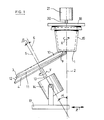
- a flat surface 1 to be treated is given a rotational movement, for example in the direction of arrow X with a diamond strip annular 3 of a rotary grinding wheel 4 of frustoconical or toric shape, the grinding wheel 4 rotating about its axis of rotation 5 inclined at an angle ⁇ relative to the axis 2.
- the strip 3 is driven in a rotational movement in the direction of the arrow Y around its geometric axis 6 inclined in turn by an angle ⁇ relative to the axis of rotation 5 of the grinding wheel 4.
- the speeds and the directions of rotation of the surface 1 and of the strip diamond 3 can be the same or different.
- the surface 1 is constantly in contact with the diamond strip 3 by a contact generator 7 which cuts the axis of rotation 2 of the surface 1.
- the surface 1 can be that of an object to be polished 19 fixed to a gripping head 18, this head being rotated around a shaft 20.
- the gripping head 18 can be moved by a supply means 21 so as to apply the surface to be treated 1 against the strip 3.
- the hatched area 8 represents a contact area of the diamond crown 3 with the surface 1.
- the contact area between the strip 3 and the surface to be treated 1 is moved by translation of a carriage 17 in the direction of the arrows Z .
- Figure 3 shows a frustoconical or toric wheel 4 carrying the diamond strip 3 eccentric.
- This wheel 4 is wedged on a floating shaft 13 of a motor 14.
- the axis 5 of the shaft 13 is inclined at an angle ⁇ relative to the geometric axis 2 of the surface to be treated 1 (see FIG. 4 ).
- a substantially constant pressure is applied by the diamond crown 3 to the surface 1 during the treatment of the latter.
- This constant pressure is ensured by the floating shaft 13 which is subject himself to a thrust exerted by a fluid as described in Belgian Patent No. 696,828. Due to the presence of a support made of elastic material, this pressure provides the grinding wheel with a generally generally elliptical contact surface 8 allowing, during polishing, a very localized heating which brings the microfusion to the surface 1 of the material to be polished.
- Grinding and polishing the glass to the conventional mechanical finish involves four stages of work: - roughing or roughing with an abrasive, generally free of silicon carbide or fixed such as diamond; - cutting with a harder abrasive such as corundum or diamond; - polishing with an abrasive such as pumice stone on a cork backing, and - buffing with an abrasive such as cerium oxide on a fabric-based support.
- an abrasive generally free of silicon carbide or fixed such as diamond
- - cutting with a harder abrasive such as corundum or diamond
- - polishing with an abrasive such as pumice stone on a cork backing
- - buffing with an abrasive such as cerium oxide on a fabric-based support.
- the first step corresponds to an abrasion work to define the desired geometry or the shape blank. It gives a rough surface.
- the size then gives a matt surface, the polishing brings back a certain shine and the buffing returns the original shine of the blown or pressed part.
- Polishing and buffing correspond to microfusion work.
- the intermediate stages combine the abrasion effect and the microfusion effect in variable proportions.
- Microfusion is an operation that occurs by heating between the glass and the polishing wheel. This results in a creep of the glass surface and a restoration of the shine. Previous abrasion defects due to roughing and size appear if the underlying layers destabilized at each grinding step have not been removed by each grinding wheel following the previous step.
- the disadvantages of the conventional system are, due to the use of various abrasives and the presentation of these, that is to say free for roughing operations using grains or agglomerated and free for finishing operations each operation must be carried out "separately".
- the total process time is therefore the sum of the separate times.
- the process which in the finishing phases is essentially manual, does not allow the control of the depth of successive passes. It is slow and expensive.
- the frustoconical or toric wheel can have an inside diameter of about 75 mm to 150 mm, preferably 90 mm, and an outside diameter of 100 mm to 200 mm, preferably 150 mm.
- the diamond strip 3 can have a width of 10 mm to 30 mm, preferably 15 mm and an outside diameter of 135 mm and an inside diameter of around 105 mm.
- the angle ⁇ of the axis of rotation 5 of the grinding wheel with the axis of rotation of the surface 1 can be approximately 2 to 45 degrees, preferably 4 degrees.
- the inclination ⁇ of the geometric axis 6 of the strip 3 depends on the eccentric position of the strip 3 on the frustoconical or toric flank of the grinding wheel 12.
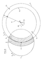
- FIG. 5 partially shows the extreme positions (areas 8 and 9 of FIG. 2) occupied by the diamond strip 3 during each rotation of the grinding wheel 5, when the diamond strip 3 such as a veiled wheel turns in contact of the surface 1 around a center of rotation moving along the axis of rotation 5 of the grinding wheel 4.
- FIG. 5 an extreme position occupied by the diamond strip 3, in which its inner edge 10 is adjacent to the axis of rotation 2 of the surface 1 is shown in solid lines, while the other extreme position in which the outer edge 11 of the crown is adjacent to the axis of rotation 2 of the surface 2 is shown in phantom.
- Cerium oxide buffing can be applied directly and in minimum time. Manually, the operator performs the work in hidden time because the previous operations are automatic.
- the buffing can also be carried out automatically on one of the work stations, similar to each other, of the machine according to the invention.
- the buffing, which is by definition, the last polishing operation is for example carried out with a strip of felt under watering using a suspension of cerium oxide.
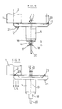
- FIG. 6 schematically shows how a flat grinding wheel provided with an eccentric abrasive strip 3 can be used.
- the abrasive strip becomes a diamond annular ring 23 driven in a rotational movement around an axis 26 distant from its geometric axis 24, by a distance less than the radius R of the ring, the axis of rotation 26 of this ring 23 being parallel to its geometric axis 24, as well as to the axis of rotation 2 of the surface to be treated.
- the hatched areas 8 and 9 represent the extreme contact areas of the diamond crown 3 with the surface 1.
- the area of contact of the latter with the surface to be treated 1 passes through the two aforementioned extreme positions shown diagrammatically by the areas 8 and 9.
- the inner edge 10 of the diamond crown 23 is adjacent to the axis of rotation 2 of the surface 1, while in the position represented by the area 9, it is the edge outside 11 of the diamond crown 23 which is adjacent thereto (see also FIG. 8).
- the diamond crown 23 is mounted eccentrically on the cup wheel 12 pivoting about the axis of rotation 26.
- the geometric axis 24 of the diamond crown 23 is offset with respect to the axis of rotation 26 by a distance D substantially equal to half the width L of the diamond crown 23.
- the cup wheel 12 is wedged on a floating shaft 13 of an electric motor 14.
- the axis of the shaft 13 is eccentric relative to the geometric axis 24 of the diamond crown 23.
- a substantially constant pressure is applied by the diamond crown 23 to the surface 1 during the treatment of the latter.
- This constant pressure is provided by the floating shaft 13 which is itself subjected to a thrust exerted by a fluid.
- the diamond crown 23 can have an outside diameter DE of 150 millimeters and the width L of the diamond crown 23 can be 15 millimeters.
- the distance D between the geometric axis 24 of the diamond crown and the axis of rotation 26 of the latter can be approximately 7.5 millimeters.
- the distance D can obviously be different from this value, but it must preferably be less than the radius R of the diamond crown 23.
- FIG. 7 shows the cup wheel 12 moved by a half-turn relative to FIG. 6.
- FIG. 7 diagrams are shown at 21 of the unbalances mounted on the grinding wheel 12 carrying the diamond crown 23, these unbalances 21 being intended to balance the grinding wheel 12 and the crown 23, so as to prevent them from undergoing vibrations during of their rotational movements around the eccentric axis 26.
- FIG. 8 partially shows the extreme positions (areas 8 and 9 of FIG. 2) occupied by the diamond crown 23 rotating around its eccentric axis 6 in contact with the surface 1.
- FIG. 8 the position of the diamond crown 23, in which its inner edge 10 is adjacent to the axis of rotation 2 of the surface 1 is shown in solid lines, while the other extreme position in which the outer edge 11 of the crown is adjacent to the axis of rotation 2 of the surface 2 is shown in phantom.
Landscapes
- Engineering & Computer Science (AREA)
- Mechanical Engineering (AREA)
- Chemical & Material Sciences (AREA)
- Ceramic Engineering (AREA)
- Inorganic Chemistry (AREA)
- Grinding And Polishing Of Tertiary Curved Surfaces And Surfaces With Complex Shapes (AREA)
- Grinding Of Cylindrical And Plane Surfaces (AREA)
Priority Applications (1)
| Application Number | Priority Date | Filing Date | Title |
|---|---|---|---|
| AT87870115T ATE71008T1 (de) | 1986-08-19 | 1987-08-18 | Verfahren und vorrichtung zum mechanischen schleifen und polieren der flaeche eines mineralischen materials, insbesondere aus glas. |
Applications Claiming Priority (4)
| Application Number | Priority Date | Filing Date | Title |
|---|---|---|---|
| BE217058 | 1986-08-19 | ||
| BE0/217058A BE905292A (fr) | 1986-08-19 | 1986-08-19 | Procede pour polir ou adoucir une surface plane d'un objet en verre. |
| BE8700437 | 1987-04-22 | ||
| BE8700437A BE1000491A5 (fr) | 1987-04-22 | 1987-04-22 | Procede et machine pour meuler et polir mecaniquement une surface en materiau mineral, plus specialement en verre. |
Publications (3)
| Publication Number | Publication Date |
|---|---|
| EP0257013A2 true EP0257013A2 (de) | 1988-02-24 |
| EP0257013A3 EP0257013A3 (en) | 1988-05-11 |
| EP0257013B1 EP0257013B1 (de) | 1992-01-02 |
Family
ID=25655021
Family Applications (1)
| Application Number | Title | Priority Date | Filing Date |
|---|---|---|---|
| EP87870115A Expired - Lifetime EP0257013B1 (de) | 1986-08-19 | 1987-08-18 | Verfahren und Vorrichtung zum mechanischen Schleifen und Polieren der Fläche eines mineralischen Materials, insbesondere aus Glas |
Country Status (3)
| Country | Link |
|---|---|
| EP (1) | EP0257013B1 (de) |
| JP (1) | JPH01121159A (de) |
| DE (1) | DE3775655D1 (de) |
Cited By (9)
| Publication number | Priority date | Publication date | Assignee | Title |
|---|---|---|---|---|
| BE1002432A4 (nl) * | 1986-09-24 | 1991-02-05 | Lindner Maschinen Gmbh W | Bewerkingstoestel voor de bewerking der randzones van glaswaren. |
| US5514025A (en) * | 1991-05-24 | 1996-05-07 | Shin-Etsu Handotai Co. Ltd. | Apparatus and method for chamfering the peripheral edge of a wafer to specular finish |
| EP0868976A3 (de) * | 1997-03-06 | 2000-08-23 | Keltech Engineering | Läppvorrichtung und Verfahren zum Hochgeschwindigkeitsläppen mit einer drehbare Schleifplatte |
| CN102452034A (zh) * | 2010-10-26 | 2012-05-16 | 洛阳北方玻璃技术股份有限公司 | 玻璃圆孔自动抛光机 |
| CN102601691A (zh) * | 2012-04-06 | 2012-07-25 | 大连理工大学 | 一种圆锥面磨削方法 |
| CN113681440A (zh) * | 2021-09-24 | 2021-11-23 | 义乌工商职业技术学院 | 加工圆柱工件的液动压抛光设备 |
| CN114425737A (zh) * | 2022-01-26 | 2022-05-03 | 黄河水利职业技术学院 | 一种接口锥智能超声抛光清洗装置 |
| CN117020911A (zh) * | 2023-10-09 | 2023-11-10 | 河南百合特种光学研究院有限公司 | 灯杯整形抛光工艺及装置 |
| CN117067051A (zh) * | 2023-10-18 | 2023-11-17 | 赣州得辉达科技有限公司 | 一种音响外壳自动打磨装置 |
Families Citing this family (4)
| Publication number | Priority date | Publication date | Assignee | Title |
|---|---|---|---|---|
| JP2006068888A (ja) * | 2004-09-06 | 2006-03-16 | Speedfam Co Ltd | 定盤の製造方法及び平面研磨装置 |
| CN106002550B (zh) * | 2016-06-08 | 2018-06-29 | 芜湖万辰电光源科技有限公司 | 玻璃杯打磨一体机 |
| CN108789124A (zh) * | 2018-07-06 | 2018-11-13 | 福建福晶科技股份有限公司 | 一种锥形产品的加工方法 |
| CN110788698B (zh) * | 2019-10-14 | 2020-11-06 | 上海交通大学 | 基于雾化CeO2辅助轴向进给的磨削加工方法、系统、介质及设备 |
Family Cites Families (11)
| Publication number | Priority date | Publication date | Assignee | Title |
|---|---|---|---|---|
| US2676439A (en) * | 1952-07-18 | 1954-04-27 | Baker Dan Dysart | Rotary sander |
| US3007288A (en) * | 1957-12-16 | 1961-11-07 | Pilkington Brothers Ltd | Production of polished bevels on glass plates |
| FR1268852A (fr) * | 1959-10-17 | 1961-08-04 | Fortuna Werke Spezialmaschinen | Procédé et appareil pour l'équilibrage dynamique et statique de machines à meuler équipées d'un indicateur d'oscillations |
| US3030744A (en) * | 1960-03-08 | 1962-04-24 | Harig Mfg Corp | Air film bearing for machine tools |
| US3119210A (en) * | 1961-08-08 | 1964-01-28 | Roland E Doeden | Air operated tool |
| BE696828A (de) * | 1967-04-10 | 1967-09-18 | ||
| DE2016615A1 (de) * | 1970-04-08 | 1971-10-28 | Vüleroy & Boch, Keramische Werke KG, 6642 Mettlach | Vorrichtung zum Schleifen des Bodens von Glasern |
| US3624969A (en) * | 1970-07-15 | 1971-12-07 | American Optical Corp | Lens generating apparatus |
| JPS5217915B1 (de) * | 1970-08-05 | 1977-05-18 | ||
| CH651773A5 (fr) * | 1983-03-31 | 1985-10-15 | Comadur Sa | Procede pour former une lentille convergente dans une plaque d'un materiau mineral transparent. |
| IT1169121B (it) * | 1983-04-27 | 1987-05-27 | Ermanno Pacini | Rullo troncoconico a superficie abrasiva per utensile levigatore a rulli troncoconici radiali |
-
1987
- 1987-08-18 EP EP87870115A patent/EP0257013B1/de not_active Expired - Lifetime
- 1987-08-18 DE DE8787870115T patent/DE3775655D1/de not_active Expired - Lifetime
- 1987-08-19 JP JP20428887A patent/JPH01121159A/ja active Pending
Cited By (13)
| Publication number | Priority date | Publication date | Assignee | Title |
|---|---|---|---|---|
| BE1002432A4 (nl) * | 1986-09-24 | 1991-02-05 | Lindner Maschinen Gmbh W | Bewerkingstoestel voor de bewerking der randzones van glaswaren. |
| US5514025A (en) * | 1991-05-24 | 1996-05-07 | Shin-Etsu Handotai Co. Ltd. | Apparatus and method for chamfering the peripheral edge of a wafer to specular finish |
| EP0868976A3 (de) * | 1997-03-06 | 2000-08-23 | Keltech Engineering | Läppvorrichtung und Verfahren zum Hochgeschwindigkeitsläppen mit einer drehbare Schleifplatte |
| CN102452034A (zh) * | 2010-10-26 | 2012-05-16 | 洛阳北方玻璃技术股份有限公司 | 玻璃圆孔自动抛光机 |
| CN102452034B (zh) * | 2010-10-26 | 2013-08-14 | 洛阳北方玻璃技术股份有限公司 | 玻璃圆孔自动抛光机 |
| CN102601691A (zh) * | 2012-04-06 | 2012-07-25 | 大连理工大学 | 一种圆锥面磨削方法 |
| CN113681440A (zh) * | 2021-09-24 | 2021-11-23 | 义乌工商职业技术学院 | 加工圆柱工件的液动压抛光设备 |
| CN113681440B (zh) * | 2021-09-24 | 2022-11-08 | 义乌工商职业技术学院 | 加工圆柱工件的液动压抛光设备 |
| CN114425737A (zh) * | 2022-01-26 | 2022-05-03 | 黄河水利职业技术学院 | 一种接口锥智能超声抛光清洗装置 |
| CN117020911A (zh) * | 2023-10-09 | 2023-11-10 | 河南百合特种光学研究院有限公司 | 灯杯整形抛光工艺及装置 |
| CN117020911B (zh) * | 2023-10-09 | 2024-01-16 | 河南百合特种光学研究院有限公司 | 灯杯整形抛光工艺及装置 |
| CN117067051A (zh) * | 2023-10-18 | 2023-11-17 | 赣州得辉达科技有限公司 | 一种音响外壳自动打磨装置 |
| CN117067051B (zh) * | 2023-10-18 | 2023-12-26 | 赣州得辉达科技有限公司 | 一种音响外壳自动打磨装置 |
Also Published As
| Publication number | Publication date |
|---|---|
| JPH01121159A (ja) | 1989-05-12 |
| DE3775655D1 (de) | 1992-02-13 |
| EP0257013A3 (en) | 1988-05-11 |
| EP0257013B1 (de) | 1992-01-02 |
Similar Documents
| Publication | Publication Date | Title |
|---|---|---|
| EP0257013B1 (de) | Verfahren und Vorrichtung zum mechanischen Schleifen und Polieren der Fläche eines mineralischen Materials, insbesondere aus Glas | |
| CN1138612C (zh) | 抛光晶片边缘的方法和设备 | |
| FR2690639A1 (fr) | Dispositif pour le travail de finition du pourtour de verres de lunettes. | |
| BE1001701A3 (fr) | Meule a boisseau et utilisation de celle-ci pour le meulage et le polissage mecaniques du verre. | |
| JPH07164293A (ja) | バリ取りブラシ装置及びマシニングセンタ装着用ホルダを有するバリ取りブラシ | |
| JPH1080849A (ja) | 半導体ウェーハ縁部の材料研削加工方法 | |
| JPH0760624A (ja) | 半導体円板のエッジを研磨する方法 | |
| EP0344142B1 (de) | Verfahren zum kombinierten Schneiden und Nachbearbeiten von Glaswaren oder Kristallwaren mittels abrasiver Werkzeuge und Vorrichtung zur Durchführung des Verfahrens | |
| BE1000491A5 (fr) | Procede et machine pour meuler et polir mecaniquement une surface en materiau mineral, plus specialement en verre. | |
| JP2000317835A5 (de) | ||
| JP3290235B2 (ja) | 研摩方法及び研摩装置 | |
| FR2677912A1 (fr) | Dispositif et procede pour arrondir les aretes de disques semiconducteurs. | |
| US3603039A (en) | Method of and apparatus for machining articles | |
| FR2575101A1 (fr) | Outil pour l'usinage de surfaces optiques et machine utilisant un tel outil | |
| BE905292A (fr) | Procede pour polir ou adoucir une surface plane d'un objet en verre. | |
| JP2000246635A (ja) | 砥石の再生方法およびその装置 | |
| BE1005799A3 (fr) | Meule pour le decoupage ou le polissage de diamants. | |
| JP2001001262A (ja) | 総型工具のツルーイング方法およびツルアー | |
| JP2561969Y2 (ja) | 平面研削盤のドレッシング装置 | |
| JP2004174673A (ja) | レンズ加工方法 | |
| JP3065395U (ja) | 流体球面研磨機 | |
| JPH0569309A (ja) | 超仕上方法 | |
| FR2752182A1 (fr) | Buse d'arrosage et de decrassage pour meule de rectification | |
| JP2008142836A (ja) | ブラシ研削装置及びブラシ研削方法 | |
| JPH06126618A (ja) | 砥石成形用の研削盤 |
Legal Events
| Date | Code | Title | Description |
|---|---|---|---|
| PUAI | Public reference made under article 153(3) epc to a published international application that has entered the european phase |
Free format text: ORIGINAL CODE: 0009012 |
|
| AK | Designated contracting states |
Kind code of ref document: A2 Designated state(s): AT BE CH DE ES FR GB GR IT LI LU NL SE |
|
| PUAL | Search report despatched |
Free format text: ORIGINAL CODE: 0009013 |
|
| AK | Designated contracting states |
Kind code of ref document: A3 Designated state(s): AT BE CH DE ES FR GB GR IT LI LU NL SE |
|
| 17P | Request for examination filed |
Effective date: 19881003 |
|
| 17Q | First examination report despatched |
Effective date: 19900209 |
|
| GRAA | (expected) grant |
Free format text: ORIGINAL CODE: 0009210 |
|
| AK | Designated contracting states |
Kind code of ref document: B1 Designated state(s): AT BE CH DE ES FR GB GR IT LI LU NL SE |
|
| PG25 | Lapsed in a contracting state [announced via postgrant information from national office to epo] |
Ref country code: NL Effective date: 19920102 Ref country code: GR Free format text: LAPSE BECAUSE OF FAILURE TO SUBMIT A TRANSLATION OF THE DESCRIPTION OR TO PAY THE FEE WITHIN THE PRESCRIBED TIME-LIMIT Effective date: 19920102 Ref country code: AT Effective date: 19920102 |
|
| REF | Corresponds to: |
Ref document number: 71008 Country of ref document: AT Date of ref document: 19920115 Kind code of ref document: T |
|
| REF | Corresponds to: |
Ref document number: 3775655 Country of ref document: DE Date of ref document: 19920213 |
|
| ITF | It: translation for a ep patent filed | ||
| PG25 | Lapsed in a contracting state [announced via postgrant information from national office to epo] |
Ref country code: ES Free format text: LAPSE BECAUSE OF FAILURE TO SUBMIT A TRANSLATION OF THE DESCRIPTION OR TO PAY THE FEE WITHIN THE PRESCRIBED TIME-LIMIT Effective date: 19920413 |
|
| GBT | Gb: translation of ep patent filed (gb section 77(6)(a)/1977) | ||
| NLV1 | Nl: lapsed or annulled due to failure to fulfill the requirements of art. 29p and 29m of the patents act | ||
| PGFP | Annual fee paid to national office [announced via postgrant information from national office to epo] |
Ref country code: GB Payment date: 19920817 Year of fee payment: 6 |
|
| PGFP | Annual fee paid to national office [announced via postgrant information from national office to epo] |
Ref country code: SE Payment date: 19920818 Year of fee payment: 6 Ref country code: DE Payment date: 19920818 Year of fee payment: 6 |
|
| PGFP | Annual fee paid to national office [announced via postgrant information from national office to epo] |
Ref country code: FR Payment date: 19920828 Year of fee payment: 6 |
|
| PG25 | Lapsed in a contracting state [announced via postgrant information from national office to epo] |
Ref country code: LU Free format text: LAPSE BECAUSE OF NON-PAYMENT OF DUE FEES Effective date: 19920831 Ref country code: LI Effective date: 19920831 Ref country code: CH Effective date: 19920831 |
|
| PGFP | Annual fee paid to national office [announced via postgrant information from national office to epo] |
Ref country code: BE Payment date: 19920903 Year of fee payment: 6 |
|
| PLBE | No opposition filed within time limit |
Free format text: ORIGINAL CODE: 0009261 |
|
| STAA | Information on the status of an ep patent application or granted ep patent |
Free format text: STATUS: NO OPPOSITION FILED WITHIN TIME LIMIT |
|
| 26N | No opposition filed | ||
| REG | Reference to a national code |
Ref country code: CH Ref legal event code: PL |
|
| PG25 | Lapsed in a contracting state [announced via postgrant information from national office to epo] |
Ref country code: GB Effective date: 19930818 |
|
| PG25 | Lapsed in a contracting state [announced via postgrant information from national office to epo] |
Ref country code: SE Effective date: 19930819 |
|
| PG25 | Lapsed in a contracting state [announced via postgrant information from national office to epo] |
Ref country code: BE Effective date: 19930831 |
|
| BERE | Be: lapsed |
Owner name: BIEBUYCK LEON Effective date: 19930831 |
|
| GBPC | Gb: european patent ceased through non-payment of renewal fee |
Effective date: 19930818 |
|
| PG25 | Lapsed in a contracting state [announced via postgrant information from national office to epo] |
Ref country code: FR Effective date: 19940429 |
|
| PG25 | Lapsed in a contracting state [announced via postgrant information from national office to epo] |
Ref country code: DE Effective date: 19940503 |
|
| REG | Reference to a national code |
Ref country code: FR Ref legal event code: ST |
|
| EUG | Se: european patent has lapsed |
Ref document number: 87870115.0 Effective date: 19940310 |
|
| PG25 | Lapsed in a contracting state [announced via postgrant information from national office to epo] |
Ref country code: IT Free format text: LAPSE BECAUSE OF NON-PAYMENT OF DUE FEES;WARNING: LAPSES OF ITALIAN PATENTS WITH EFFECTIVE DATE BEFORE 2007 MAY HAVE OCCURRED AT ANY TIME BEFORE 2007. THE CORRECT EFFECTIVE DATE MAY BE DIFFERENT FROM THE ONE RECORDED. Effective date: 20050818 |