EP0257192A1 - Procédé d'élimination d'une résine échangeuse d'ions par décomposition oxydante - Google Patents
Procédé d'élimination d'une résine échangeuse d'ions par décomposition oxydante Download PDFInfo
- Publication number
- EP0257192A1 EP0257192A1 EP87106105A EP87106105A EP0257192A1 EP 0257192 A1 EP0257192 A1 EP 0257192A1 EP 87106105 A EP87106105 A EP 87106105A EP 87106105 A EP87106105 A EP 87106105A EP 0257192 A1 EP0257192 A1 EP 0257192A1
- Authority
- EP
- European Patent Office
- Prior art keywords
- exchange resin
- resin
- ion
- decomposition
- hydrogen peroxide
- Prior art date
- Legal status (The legal status is an assumption and is not a legal conclusion. Google has not performed a legal analysis and makes no representation as to the accuracy of the status listed.)
- Granted
Links
Images







Classifications
-
- G—PHYSICS
- G21—NUCLEAR PHYSICS; NUCLEAR ENGINEERING
- G21F—PROTECTION AGAINST X-RADIATION, GAMMA RADIATION, CORPUSCULAR RADIATION OR PARTICLE BOMBARDMENT; TREATING RADIOACTIVELY CONTAMINATED MATERIAL; DECONTAMINATION ARRANGEMENTS THEREFOR
- G21F9/00—Treating radioactively contaminated material; Decontamination arrangements therefor
- G21F9/04—Treating liquids
- G21F9/06—Processing
- G21F9/14—Processing by incineration; by calcination, e.g. desiccation
-
- Y—GENERAL TAGGING OF NEW TECHNOLOGICAL DEVELOPMENTS; GENERAL TAGGING OF CROSS-SECTIONAL TECHNOLOGIES SPANNING OVER SEVERAL SECTIONS OF THE IPC; TECHNICAL SUBJECTS COVERED BY FORMER USPC CROSS-REFERENCE ART COLLECTIONS [XRACs] AND DIGESTS
- Y10—TECHNICAL SUBJECTS COVERED BY FORMER USPC
- Y10S—TECHNICAL SUBJECTS COVERED BY FORMER USPC CROSS-REFERENCE ART COLLECTIONS [XRACs] AND DIGESTS
- Y10S210/00—Liquid purification or separation
- Y10S210/902—Materials removed
- Y10S210/908—Organic
Definitions
- the present invention relates to a method of chemical decomposition by which the volumes of spent radioactive ion-exchange resins (hereinafter sometimes referred to as waste resins) originating from atomic energy facilities can be reduced.
- Ion-exchange resins are extensively used in many applications such as purification of water, treatment of wastewaters, and separation of various elements. They are also used in large quantities in the field of atomic energy for the purpose of purifying cooling water in nuclear reactors and treating liquid wastes. Therefore, treatment and disposal of spent waste ion-exchange resins containing radioactive substances has been a serious concern in this field.
- the method in common use in the technology of disposal of radioactive waste ion-exchange resins is to dehydrate the resins, solidify them by incorporation in cements, plastics, etc., place the solidified wastes in containers, and store them for a prescribed number of years, often almost perpetually.
- the waste resins treated by this method are not reduced significantly in volume and have posed substantial problems in the area of waste storage and management.
- combustion incineration
- pyrolysis pyrolysis
- acid decomposition a method for reducing the volumes of waste ion-exchange resins, but none of these have proved to be a complete solution to the problem.
- the combustion method has the advantage of achieving rapid treatment but, at the same time, it requires complicated off-gas lines for handling dust and tars, and/or produces volatile radioactive compounds.
- the last-mentioned problem is absent from the pyrolysis method, but, on the other hand, it yields high residual contents of carbonaceous materials, and still requires complicated flow systems as in the case of the incineration method.
- the spent ion-exchange resins can be decomposed by successive treatments with concentrated sulfuric acid and nitric acid at a temperature of about 260°C.
- this method is free from any of the problems associated with the first two methods, it has the disadvantage of generating NOx and SOx.
- the reaction vessel must be made of ' an expensive material such as tantalum that is capable of withstanding the extremely high temperatures employed.
- the volume of the waste resins being treated cannot be reduced to the desired extent, since large quantities of salts form during neutralization of the reaction solution.
- the prior art technology also has another problem that has to be solved before it can be employed in practical applications, viz., leakage of radioactivity from mechanical seals in the agitating and mixing apparatus used for achieving accelerated decomposition reaction.
- An object, therefore, of the present invention is to provide a method by which a radioactive ion-exchange resin, and in particular, a radioactive anion-exchange resin, can be decomposed with hydrogen peroxide used as an oxidizing agent in the presence of iron and copper ions used as catalysts with high percent decomposition being achieved in a short period of treatment with low consumption of hydrogen peroxide and the production of organic sludge being held to minimum levels.
- Another object of the present invention is to provide an apparatus that can be used to implement the aforementioned method of decomposing a radioactive ion-exchange resin.
- the first object of the present invention can be attained by a method of oxidative decomposition of a radioactive ion-exchange resin, and, in particular, a radioactive anion-exchange resin with hydrogen peroxide used as an oxidizing agent in the presence of iron and copper ions used as catalysts, wherein citric acid ions are preliminarily adsorbed on the anion-exchange resin before oxidative decomposition is effected or citric acid coexists with the anion-exchange resin in the oxidatively decomposing system.
- the wieght ratio of H 2 0 2 to resin is reduced to 17 or below (i.e., the consumption of hydrogen peroxide is reduced) and yet a satisfactorily high efficiency of resin decomposition can be attained within a reaction time that is no longer than half of the heretofore required period.
- the first object of the present invention is also attained in a manner by crushing the waste ion-exchange resin into fine particles when or before it is mixed with hydrogen peroxide and the decomposition cata- lys ts.
- the waste ion-exchange resin may be one adsorbing citric acid ions.
- the concentration of the aqueous solution of hydrogen peroxide to be added to the reacticn system of oxidative decomposition is not limited to any particular value and conventional 30% or 60% hydrogen peroxide may satisfactorily be used.
- the method of the present invention is carried out with the ratio of H 2 0 2 (on a net weight basis) to the ion-exchange resin feed (dry weight basis) being adjusted to no higher than 17 (i.e., 17/1; hereinafter, the various ratios to which reference is made are expressed as single numbers).
- the method of the present invention may be carried out within the range of 17 to 3, preferably 17 to 4, more preferably 10 to 4 in H 2 0 2/ resin ratio.
- H 2 0 2 -rich conditions for example, H 2 0 2/ resin ratio is higher than 20, the method of the present invention need not be used and an appropriate combination of iron and copper catalysts can achieve efficient decomposition of the waste ion-exchange resin while forming a reduced amount of organic sludge.
- Oxidative reaction should be carried out with the waste ion-exchange resin being dispersed or suspended in water.
- the volume of the reaction solution is desirably within the range of from about 10 ml to about 30 ml per gram of dry resin.
- the iron and copper ions functioning as catalysts are preferably derived from water-soluble salts such as . sulfates, nitrates and chlorides, such as FeS0 4 , FeSO 4 ⁇ -7H 2 O, Fe(SO 4 )(NH 4 )SO 4 ⁇ 6H 2 O, Fe(NH 4 )(SO 4 ) 2 ⁇ 12H 2 ,O CuSO 4 , CUSO 4 ⁇ 5H 2 O, etc.
- the concentration of iron catalyst used in the reaction system of oxidative decomposition is preferably within the range of from 0.0005 to 0.02 M, and more preferably from 0.002 to 0.15 M.
- the concentration of copper catalyst is preferably within the range of from 0.002 to 0.15 M, and more preferably from 0.005 to 0.1 M. If these conditions are used, better results are attained in terms of sludge formation and decomposition efficiency.
- the H 2 0 2 /resin ratio is selected to have a value of no higher than 17, and decomposition of a radioactive ion-exchange resin with H 2 0 2 in the presence of copper and iron catalysts is effected after the resin is subjected to ion-exchange for citric acid ions in the form of either citric acid or a salt thereof, e.g., sodium citrate, etc.
- the oxidative decomposition of a radioactive ion-exchange resin is carried out under a pH value of no higher than 17 and in the presence of either citric acid or a salt thereof.
- the radioactive ion-exchange resin adsorbs the citric acid ions in an amount of 70% or more, preferably '80% or more, and most preferably 90% or more based on a total ion-exchangeable ability of ion-exchange resin to be treated, the ion-exchangeable ability being represented by an equivalent per gram.
- the anion-exchange resin used in the present invention preferably includes a strong alkaline anion-exchange resin which is commercially available, for example, SNA-1 (trademark for product produced by Mitsubishi Kasei Corporation) having the following repeating units.
- SNA-1 trademark for product produced by Mitsubishi Kasei Corporation
- the cation-exchange resin used together with the above described anion-exchange resin used in the present invention preferably includes a strong acidic cation-exchange resin which is commercially available, for example, SKN-1 (trademark for product produced by Mitsubishi Kasei Corporation) having the following repeating units.
- SKN-1 trademark for product produced by Mitsubishi Kasei Corporation
- the method of the present invention may be implemented with a continuous or batch reactor for effecting oxidative decomposition of the resin feed.
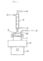
- F ig. 1 is a schematic drawing of a continuous reactor.
- a reaction vessel indicated by 1 is charged with an aqueous solution of the necessary catalysts and a waste ion-exchange resin.
- the charged reaction solution is stirred with a magnetic stirrer 2.
- the temperature of the reaction system is held constant by means of a water bath 3.
- a constant flow of an aqueous solution of hydrogen peroxide is fed into the reaction vessel through an inlet 4.
- the concentrations of the catalysts are held substantially constant by supplying a concentrated catalyst solution through an inlet 5.
- the catalyst concentrations may be set by any suitable method; they may be held substantially constant throughout the reaction; alternatively, the concentrations may be set in the initial period and left uncontrolled for the rest of the reaction period. Satisfactory treatments are.possible if the concentrations of catalysts in the reaction solution before and after the reaction are kept within the ranges specified herein.
- the waste ion-exchange resin may be fed in a continuous manner.
- Decomposition can be accomplished if the reaction temperature is within the range of from ambient temperatures to 100°C and temperatures of at least 90°C are preferably employed in order to attain a higher percentage of decomposition.
- the reaction vessel is preferably equipped with a stirrer.
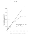
- Fig. 2 is a graph showing the relationship between the H 2 O 2 /resin ratio, sludge weight, and percent decomposition.
- the H 2 0 2/ resin ratio means the amount of hydrogen peroxide (in grams for 100% H 2 0 2 ) consumed for decomposing one gram on a dry weight basis of the ion-exchange resin.
- H 2 0 2/ resin ratios of about 20 [see, for example, the working examples given in the specification of Japanese Patent Application (OPI) No. 44700/84]. If the matrix of a waste ion-exchange resin to be treated is polystyrene, a H 2 0 2/ resin ratio of approximately 6.5 is sufficient to achieve 100% decomposition of polystyrene and the H 2 0 2 supplied is more than necessary if higher H 2 0 2 /resin ratios are employed.
- sludge formation is negligible if the H 2 0 2/ resin ratio is about 20, but an increasing amount of sludge will form if the ratio becomes 17 or lower by reducing the amount of H 2 0 2 used.
- discussion of the prior art technology for oxidative decomposition of waste ion-exchange resins has been made on the basis of H 2 0 2/ resin ratios of about 20 or more, and no attention has been paid to the formation of organic sludge.
- the present inventors noted the occurrence of sludge formation and unravelled the process of its formation and the factors that were involved as a result of conducting intensive studies in this aspect. The present invention has been accomplished on the basis of these findings.
- Fig. 3 shows the concept of the process of decomposition of an anion-exchange resin.
- an anion-exchange resin is converted to soluble organic matter and insoluble organic matter (i.e., sludge which actually is a mixture of organic matter, iron, and copper), and the soluble organic matter is eventually decomposed into water and C0 2 gas.
- H 2 0 2 -rich conditions H 2 0 2/ resin ratio > 20
- the organic sludge is completely decomposed to leave no residues, but if the H 2 0 2 / resin ratio is 17 or below, part of the organic sludge is left as residue.
- the hydrogen peroxide supplied is excessive even if the H 2 0 2/ resin ratio is 10, and yet sludge formation is inevitable. Therefore, if one wants to perform oxidative decomposition of waste resins at low H 2 0 2/ resin ratios, it is important to achieve efficient treatment by minimizing the occurrence of sludge formation.
- Anion-exchange resins are known to have the following relationship between adsorbed ionic species and the efficiency of their decomposition.
- the selectivity for adsorption of ions by an anion-exchange resin decreases in the following order: citric acid
- the SO 4 2- ion is more readily adsorbed than the C1 ion and the citric acid ion is more easily adsorbed than any other ionic species.
- a Cl - form resin is less decomposable than other types of anion-exchange resins, and this is assumed to be because the Cl - ion is an inhibitor of the OH radical forming reaction.
- the present inventors have first discovered that citric acid type anion-exchange resins can be decomposed with high efficiency, and this discovery is based on their success in unravelling the peculiar mechanism behind the oxidative decomposition of anion-exchange resins.
- Fig. 4 shows, the process of decomposition of waste resins differs greatly between cation-exchange and anion-exchange resins.
- the cation-exchange resin which is comparatively easy to decompose undergoes a solid-liquid reaction (see Fig. 4 ) in which its structure is readily destroyed and dissolved in the reaction solution. This reaction proceeds very rapidly. In the subsequent liquid- liquid reaction, the resin is oxidatively decomposed to yield water and carbon dioxide as the final decomposition products.
- the behavior of the anion-exchange resin which is intended to be decomposed by the method of the present invention differs greatly from the cation-exchange resin.
- the anion-exchange resin will not be readily dissolved as a result of solid-liquid .reaction. If the resin remains solid, the efficiency of its decomposition is low and this is one of the factors that render the anion-exchange resin highly refractory to the existing decomposition techniques.
- the mechanism by which the resin remains solid is identified in Fig. 4 under the heading "sludge formation", which is discussed hereinafter in detail.
- An anion-exchange resin removes radioactive ions from water in accordance with the following reaction:
- R-N does not have very high affinity for OH - , it readily dissociates from OH and combines with any other anion that is available.
- the resin undergoes dissolution in the reaction solution and produces COOH.
- dissolution is usually meant that the resin is disintegrated into fine particles of a size of no larger than 0.45 um.
- the particles are believed to be composed of C and H, and may be expressed as P-COO - H + (where P signifies the matrix of the fine particles).
- the present inventors reasoned as follows: since the product of oxidative decomposition of an anion-exchange resin is anionic, sludge formation could be prevented by inactivating the ion-exchange capacity of the resin and this may be achieved by attaching ionic species that have strong affinity for the anion-exchange resin.
- the selectivity for adsorption of ions by an anion-exchange resin decreased in the order of: citric acid ion > SO 4 2- >I - > NO 3 - > CrO 4 2- > Br - > SCN - > Cl - > F - .
- citric acid is more readily adsorbed than any other of the ionic species listed above.
- the structure of sodium citrate is expressed by .
- citric acid is preliminarily adsorbed on the anion-exchange resin to be decomposed, the intended reaction can be effected in an efficient manner without allowing any substantial amount of sludge to form.
- citric acid ions were adsorbed on an anion-exchange resin which was then subjected to oxidative decomposition treatment.
- two types of resins were used, one being a.mixture of OH - and H + form resins, .and the other being a mixture of citric acid and H + form resins.
- OH - and Cl - form anion-exchange resins can be readily converted to the citric acid type by adsorbing citric acid or a salt thereof through routine regeneration techniques.
- the H 2 0 2 /resin ratio and the period of treatment should be carefully determined.
- the H 2 0 2/ resin ratio is preferably set to a value of no higher than 10 and the treatment is preferably completed within a period of 60 minutes.
- Table 2 shows the percent decomposition of the mixed resin of OH - and H + types for varying reaction times of 120, 60, 30 and 15 minutes with the feed of hydrogen peroxide (g) held constant.
- Table 3 shows the results for the mixed resin of citric acid and H + types.
- Fig. 6 shows the relationship of percent decomposition vs the period of treatment of each of the mixed resins.
- the present invention provides a method by which an anion-exchange resin or a mixture thereof with a cation-exchange resin is oxidatively decomposed with hydrogen peroxide in the presence of a combined catalyst of iron and copper.
- citric acid ions are preliminarily adsorbed on the anion-exchange resin before oxidative decomposition is effected, and by so doing, the resin can be decomposed at an economical H 2 0 2/ resin ratio of no higher than 10 and within a reaction time of no longer than half of the heretofore required period, and yet a satisfactorily high efficiency of decomposition can be attained.
- the objects of the present invention can be attained by crushing a granular waste ion-exchange resin into finer particles before it is oxidatively decomposed with hydrogen peroxide in the presence of a mixed catalyst of iron and copper ions.
- the crushing of the waste ion-exchange resin serves to increase its specific surface area so that its reaction with the oxidizing agent (H 2 0 2 ) in the subsequent step of oxidative decomposition can be carried out with an increased efficiency.
- the consumption of hydrogen peroxide can be decreased to a H 2 0 2/ resin ratio of 17 or below, or even to 10 or below / and yet a high efficiency of decomposition can be attained within a shorter period of reaction time.
- the waste ion-exchange resin is crushed into fine particles having an average diameter of preferably, 400 pm or less, more preferably 200 ⁇ m or less, and most preferably from 100 ⁇ m to 5 ⁇ m.
- Fig. 7 is a flowsheet of this method of the present invention for oxidatively decomposing a waste ion-exchange resin.
- a granular waste resin is first fed into the crushing stage at which it is crushed into finer particles, which are then introduced into subsequent stage of oxidative decomposition, in which the crushed resin is subjected to oxidative decomposition with hydrogen peroxide in the . presence of a mixed catalyst of iron and copper ions.
- An electromagnetic crusher is advantageously used as a means for crushing the ion-exchange resin.
- this crusher has the following three components: a vessel 8 that is made of a corrosion-resistant non-magnetic material and which contains a number of spindle-shaped working media 7 that are formed of a ferromagnetic material; and two moving field generators 9 and 10 placed on top and bottom of the vessel 8.
- Moving field generators are well known as linear motors and each consists of an iron core equipped with a multi-phase AC winding that is disposed along the magnetic poles of the core. When current is supplied to the multi-phase AC windings, moving magnetic fields are induced in opposite directions as indicated by arrows ⁇ 1 and ⁇ 2 .
- the power of the electromagnetic crushing method described above is very strong and the present inventors confirmed by experiment that this method was capable of crushing a granular ion-exchange resin into finer particles by a treatment of only few minutes.
- the results of the experiment are shown in Fig. 9:
- Diaion of Mitsubishi Chemical Industries, Limited was used as the resin sample to be treated; it consisted of particles ranging in size from 420 to 1,190 ⁇ m and was based on a polystyrene matrix.
- By performing the electromagnetic crushing method on this resin it could be crushed into particles of a size of no larger than 200 ⁇ m (average size, 30 to 50 ⁇ m) within a few minutes.
- FIG. 1 An apparatus of the type shown in Fig. 1 is employed in the oxidative decomposition stage of the process shown in Fig. 7.
- Crushing a granular ion-exchange resin into finer particles before it is decomposed oxidatively with the particles suspended in the reaction solution in the reaction vessel offers the following advantages: the specific surface area of the- resin is appreciably increased and the chance of its contact with chemicals is sufficiently increased to permit efficient progress of subsequent oxidative decomposition. As a consequence, the H 2 0 2/ resin ratio, which is a measure of H 2 0 2 consumption, and the decomposition period are significantly reduced.
- the present inventors conducted an experiment on the oxidative decomposition of ion-exchange resins with a view to evaluating the effectiveness of the method based on the principle illustrated in Fig. 7.
- a mixture of cation- and anion-exchange resins was finely divided with an electromagnetic crusher of the type shown in Fig. 8.
- Four grams of the resin particles were charged into the reaction vessel of the apparatus shown in Fig. 1 together with a mixed catalyst of iron and copper ions. After the reaction temperature had been adjusted to 95°C, 30% hydrogen peroxide was continuously fed into the reactor at a rate of 1 ml/min so as to effect oxidative decomposition of the resin.
- the efficiency of decomposition as related to the decomposition time and the H 2 0 2 /resin ratio was investigated. The same experiment and investigation were undertaken with an uncrushed granular ion-exchange resin being used as a specimen.
- Fig. 10 The profile of percent decomposition vs decomposition time as obtained by each method is shown in Fig. 10, wherein the characteristic curve A refers to the method using crushed ion-exchange resin and curve B refers to the method using uncrushed ion-exchange resin , As is clear from the characteristic graph of Fig. 10, when the decomposition period was 120 minutes during which hydrogen peroxide was supplied into the reactor for a H 2 0 2/ resin ratio of 9, the ion-exchange resin could be decomposed by at least 97% whether or not it had been crushed into finer particles.
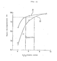
- the profile of the efficiency of decomposition vs H 2 0 2 /resin ratio is shown in Fig. 11.
- characteristic curve B the uncrushed granular ion-exchange resin could be decomposed by 95% when the H 2 O 2 /resin ratio was about 7, but when this ratio was decreased to 6 or below, the efficiency of decomposition dropped markedly.
- curve A the crushed resin could be decomposed by at least 94% for the H 2 0 2/ resin ratio range of down to about 5.
- the present inventors conducted the following experiment: resins were decomposed for a given period with the H 2 0 2 /resin ratio being varied from 4 to 9; then, the unreacted resin was recovered from the reaction vessel and subejcted to another treatment in a H 2 0 2 -rich atomsphere at H 2 0 2 /resin ratios of 10, 15, and 20 as is explained in Fig. 10 until it was completely decomposed; and the final H 2 0 2 /resin ratio was determined on the basis of the total amount of hydrogen peroxide that was consumed in the overall treatment, including the first and second decomposition.
- oxidative decomposition of ion-exchange resins can be accomplished efficiently without -making any provisions against the foaming problem.
- an aqueous solution of hydrogen peroxide that is added to the reaction system for performing oxidative decomposition of an ion-exchange resin according to the present invention
- concentration of an aqueous solution of hydrogen peroxide that is added to the reaction system for performing oxidative decomposition of an ion-exchange resin according to the present invention
- a commercial product of 30% or 60% H 2 0 2 may be employed, either as such, or after being diluted to an appropriate degree.
- the ion-exchange resin is subjected to oxidative decomposition in the form of an aqueous dispersion or suspension.
- the volume of the reaction solution may be suitably selected from the range of about 10 to 30 ml per gram of the resin in a dry state.
- Oxidative decomposition .of the resin may be carried out with either a continuous or a batch reactor.
- Decomposition can be accomplished if the reaction temperature is within the range of from ambient temperatures to 100°C and temperatures of at least 90°C are preferably employed in order to attain a higher efficiency of decomposition.
- the reaction vessel is preferably equipped with a stirrer for several reasons, one of which is to attain an increased efficiency of reaction.
- it is particularly desirable that the H 2 0 2 /resin ratio is set to a value of no higher than 10 in order to allow the advantages of the present invention, in particular, the reduction in the required amount of hydrogen peroxide, to be exhibited to the fullest extent.
- one embodiment of the present invention provides a method for oxidative decomposition of a waste granular ion-exchange resin, in which the waste resin is first crushed into finer particles before it is subjected to the step of oxidative decomposition with hydrogen peroxide in the presence of a mixed catalyst of iron and copper ions.
- the method of the present invention offers the following advantages:
- waste ion-exchange resins that occur in large quantities in atomic energy plants or facilities can be decomposed in an efficient and economical manner.
- the objects of the present invention can be attained in an even mor-e-efficient manner by employing still another embodiment, in which the reaction vessel in a reactor equipped with mixing and crushing capabilities is charged with a waste ion-exchange resin, an oxidizing agent and a decomposition catalyst, and the resin is oxidatively decomposed by crushing the resin into fine particles as it is mixed with the chemicals.
- the following advantages are attained: contact between the waste ion and the chemicals is promoted; the consumption of chemicals and the size of the reactor are reduced, and yet the rate of decomposition of the resin and the efficiency of reaction are improved; and in addition, the resin is converted into a form that can be easily treated in subsequent stages of drying and solidifying the decomposition products and other residues.
- Fig. 12 is a flowsheet of the method of decomposing a waste ion-exchange resin according to the above-described embodiment of the present invention.
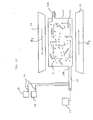
- Fig. 13 is a schematic drawing of a reactor used to crush the resin into fine particles and decomposing them into inorganic matters in the process shown in Fig. 12.
- Fig. 14 is a characteristic graph showing the ability of the reactor of Fig. 13 to crush the waste resin into fine particles.
- Fig. 15 is a characteristic graph showing the decomposing capability of the method of the present invention in comparison with the prior art technique.
- the waste resin is transported in the form of a slurry and supplied into the reactor provided for performing the step of crushing the resin into fine particles and decomposing them into inorganic matters.
- the reactor is also fed with the necessary chemicals (i.e., an oxidizing agent and a decomposition catalyst).
- the resin is crushed into fine particle, and, at the same time, it is mixed with the chemicals under stirring so as to be oxidatively decomposed into inorganic matters.
- the slurry containing the decomposition products of the waste resin and other residues such as the sludge formed of the decomposed catalyst is recovered from the reaction vessel and transferred into the subsequent drying step, in which the decomposition products and other .residues are dried with a suitable device, such as a drum dryer, centrifugal thin-film dryer, etc., to form a powder having a water content of about 1 to 5 wt%.
- the resulting dry powder is then transferred to a solidification step which is performed for the purpose of yielding a waste product that can be disposed of and stored for many years in a highly stable form.
- the reaction vessel 12 which is formed of a highly corrosion-resistant non-magnetic material, is closed except that it has an inlet 12a and an outlet 12b for the resin feed at opposite ends.
- the vessel 12 contains in its interior a number of spindle-shaped working media 13 that are formed of a ferromagnetic material.
- Two moving field generators 14 and 15 are placed on top and bottom of the vessel 12. Moving field generators are well known as linear motors and each consists of an iron core equipped with a multi-phase AC winding that is disposed along the magnetic poles of the core.
- the inlet 12a of the reaction vessel 12 is connected to a conduit 16 which in turn is connected to a waste resin feeder 17.
- Hydrogen peroxide as an oxidizing agent is held-in a reservoir 18 and a decomposition catalyst (a mixture of iron and copper ions) is placed in a reservoir 19.
- a decomposition catalyst a mixture of iron and copper ions
- Fig. 14 shows the results of the resin crushing experiment conducted by the present inventors.
- a granular waste resin having a particle size of 650 ⁇ m could be crushed to a very small size of about 10 ⁇ m by a treatment that lasted for only about 5 minutes.
- the working media 13 also afford the capabilities of stirring and mixing the resin as a result of their random movement in the vessel 12.
- the reaction vessel 12 which is filled not only with a slurry of waste resin adjusted to a concentration of about 5 to 15 wt% but also with appropriate amounts of hydrogen peroxide and catalyst, is placed under the action of moving magnetic fields, the working media 13 start to move around in the reaction vessel 12 to perform crushing and mixing operations simultaneously on the waste resin 21 so that the latter is divided into very fine particles which are almost like colloidal particles while, at the same time, they are intimately mixed with the chemicals to be decomposed into inorganic matters.
- the waste resin is first divided into fine particles as a result of violent contact with the working media and its specific surface area is sufficiently increased to provide a greater chance of contact with the chemicals.
- the stirring and mixing actions which occur simultaneously with the crushing action decreases the thickness of the boundary liquid film of the chemical solution around the waste resin so that it will readily diffuse toward the crushed waste resin.
- the chemicals will react with the waste resin as soon as they contact each other and the resin will undergo rapid oxidative decomposition into inorganic matters such as C0 2 and water.
- residues containing the sludge of catalyst such as iron, etc., are also yielded as a result of the decomposition of the resin.
- the resulting slurry containing the decomposition products and other residues is discharged from the reaction vessel 12 through outlet 12b and transferred to the subsequent drying step.
- the present inventors carried out an experiment of converting a waste resin into inorganic matter by oxidative decomposition with hydrogen peroxide in the presence of a catalyst made of iron and copper ions in accordance with the two methods.
- the profile of the efficiency of conversion to inorganic matters vs the reaction time is shown in Fig. 15, in which characteristic curve (1) refers to the prior art method and curve (2) to the method of the present invention.
- characteristic curve (1) refers to the prior art method
- curve (2) to the method of the present invention.
- two types of reactors were employed, one being the bubble column type and the other being the mechanical agitator type, but they were substantially equal to each other in their performances.
- an electromagnetic reactor of the type shown in Fig. 13 was used.
- the method of the present invention achieved almost 100% conversion of the waste resin into organic matters by a reaction that lasted for only about 4 minutes, but the prior art method took as long as about 60 minutes to attain the same level of conversion. It was therefore obvious that a significant improvement in the efficiency of reaction was achieved by employing the method of the present invention. Needless to say, the exact time required for the conversion reaction to be completed will vary with the specific properties of each waste resin but even if this point is taken into consideration, the method of the present invention is capable of decomposing waste resins of widely varying properties to commercially acceptable levels by performing the reaction for about 2 to 30 minutes. A further advantage of the reactor shown in Fig.
- the reaction vessel in a reactor equipped with mixing and crushing capabilities is charged with the waste resin, oxidizing agent and the decomposition catalyst, and the resin is decomposed by crushing the resin into fine particles as it is mixed with the chemicals.
- This has the advantage of efficiently decomposing the waste resin into inorganic" matters in a shorter period of time using smaller amounts of chemicals.
- the waste resin treated by this method is -reduced in volume and can be stored with less strict requirements for maintenance and management.
Landscapes
- Physics & Mathematics (AREA)
- Engineering & Computer Science (AREA)
- General Engineering & Computer Science (AREA)
- High Energy & Nuclear Physics (AREA)
- Separation, Recovery Or Treatment Of Waste Materials Containing Plastics (AREA)
- Treatment Of Water By Ion Exchange (AREA)
- Processing Of Solid Wastes (AREA)
Applications Claiming Priority (2)
| Application Number | Priority Date | Filing Date | Title |
|---|---|---|---|
| JP194192/86 | 1986-08-20 | ||
| JP19419286 | 1986-08-20 |
Publications (2)
| Publication Number | Publication Date |
|---|---|
| EP0257192A1 true EP0257192A1 (fr) | 1988-03-02 |
| EP0257192B1 EP0257192B1 (fr) | 1992-09-30 |
Family
ID=16320476
Family Applications (1)
| Application Number | Title | Priority Date | Filing Date |
|---|---|---|---|
| EP87106105A Expired - Lifetime EP0257192B1 (fr) | 1986-08-20 | 1987-04-28 | Procédé d'élimination d'une résine échangeuse d'ions par décomposition oxydante |
Country Status (4)
| Country | Link |
|---|---|
| US (1) | US4877558A (fr) |
| EP (1) | EP0257192B1 (fr) |
| JP (1) | JPS63158497A (fr) |
| DE (1) | DE3781984T2 (fr) |
Cited By (3)
| Publication number | Priority date | Publication date | Assignee | Title |
|---|---|---|---|---|
| WO2009090209A1 (fr) * | 2008-01-17 | 2009-07-23 | Areva Np Gmbh | Procédé pour le conditionnement de résines échangeuses d'ions radioactives |
| WO2017114797A1 (fr) * | 2015-12-30 | 2017-07-06 | Güttner Steffen | Procédé et dispositif de préparation de liquides qui comprennent des corps étrangers |
| CN110400648A (zh) * | 2019-06-20 | 2019-11-01 | 中国辐射防护研究院 | 一种核级放射性废树脂的高效氧化处理方法 |
Families Citing this family (13)
| Publication number | Priority date | Publication date | Assignee | Title |
|---|---|---|---|---|
| JPH0752238B2 (ja) * | 1989-04-28 | 1995-06-05 | 日揮株式会社 | 放射性炭素の処理方法 |
| US5122268A (en) * | 1989-08-11 | 1992-06-16 | Westinghouse Electric Corp. | Apparatus for waste disposal of radioactive hazardous waste |
| US4970005A (en) * | 1990-06-01 | 1990-11-13 | Arco Chemical Technology, Inc. | Method for treatment of wastewater containing polyether polyols |
| WO1992003829A1 (fr) * | 1990-08-28 | 1992-03-05 | Electric Power Research Institute | Procede d'oxydation de matieres organiques sans catalyseur ajoute |
| US5186842A (en) * | 1991-07-15 | 1993-02-16 | Umpqua Research Company | Method for removing low molecular weight contaminants |
| US5139679A (en) * | 1992-02-24 | 1992-08-18 | The United States Of America As Represented By The Secretary Of The Navy | Treatment of wastewater containing citric acid and triethanolamine |
| US5630785A (en) * | 1995-03-15 | 1997-05-20 | Hydromex Inc. | Process for the treatment of waste products |
| JPH11295494A (ja) * | 1998-04-08 | 1999-10-29 | Nippon Meji Physics Kk | [f−18]−フッ化物イオンの製造方法 |
| DK1647529T3 (da) * | 2003-08-22 | 2015-12-21 | Peroxychem Spain S L U | Fremgangsmåde til oprensing af spildevand |
| KR100764904B1 (ko) | 2004-06-18 | 2007-10-09 | 한국원자력연구원 | 이온교환체를 이용한 세슘 또는 스트론튬의 방사성 핵종 제거방법 |
| US7799228B2 (en) * | 2005-09-02 | 2010-09-21 | Restore + Inc. | Method for reducing natural organic fouling levels in a contaminated ion exchange resin |
| JP6400505B2 (ja) * | 2015-02-24 | 2018-10-03 | 株式会社東芝 | 使用済みイオン交換樹脂の処理方法及び処理装置 |
| DE102018131902B3 (de) * | 2018-12-12 | 2020-02-27 | Framatome Gmbh | Verfahren zur Konditionierung von Ionenaustauscherharzen und Vorrichtung zur Durchführung des Verfahrens |
Citations (5)
| Publication number | Priority date | Publication date | Assignee | Title |
|---|---|---|---|---|
| GB1574795A (en) * | 1976-08-12 | 1980-09-10 | Commissariat A L En Atomiqu | Process for conditioning contaminated ion-exchange resins |
| US4235738A (en) * | 1975-06-26 | 1980-11-25 | Vereinigte Edlsthalwerke Aktiengesellschaft (VEW) | Technique for converting spent radioactive ion exchange resins into a stable and safely storable form |
| WO1985000922A1 (fr) * | 1983-08-04 | 1985-02-28 | Studsvik Energiteknik Ab | Procede de traitement d'une resine echangeuse d'ions, organique, radioactive et epuisee |
| AT379251B (de) * | 1983-05-11 | 1985-12-10 | Oesterr Forsch Seibersdorf | Verfahren zur ueberfuehrung von anionenaustauscherharzen in einen umweltfreundlich lagerbaren zustand sowie vorrichtung zur durchfuehrung des verfahrens |
| AT379250B (de) * | 1983-05-11 | 1985-12-10 | Oesterr Forsch Seibersdorf | Einbettungsmasse und verfahren zum einbetten von anionenaustauscherharzen bzw. diese enthaltenden gemischen |
Family Cites Families (17)
| Publication number | Priority date | Publication date | Assignee | Title |
|---|---|---|---|---|
| DE379251C (de) * | 1923-08-20 | Patent Grudeofen Fabrik Walter | Feuerungseinrichtung fuer Grudekoks | |
| DE379250C (de) * | 1923-08-20 | Claude Hamilton Verity | Koch- und Heizofen mit seitlichen Kochplatten | |
| US3914388A (en) * | 1973-09-11 | 1975-10-21 | George I Cathers | Volatilization of iodine from nitric acid using peroxide |
| FI64793C (fi) * | 1977-01-27 | 1984-01-10 | Degussa | Foerfarande foer rening av avfallsvatten som innehaoller fenolfenolderivat eller fenol och formaldehyd |
| US4180603A (en) * | 1977-01-31 | 1979-12-25 | Oxy Metal Industries Corporation | Coating bath composition and method |
| US4255305A (en) * | 1977-01-31 | 1981-03-10 | Oxy Metal Industries Corporation | Coating bath composition and method |
| US4108746A (en) * | 1977-09-08 | 1978-08-22 | The United States Of America As Represented By The Secretary Of The Army | Method of oxidative degradation of phosphorous esters |
| JPS571446A (en) * | 1980-06-05 | 1982-01-06 | Japan Atom Energy Res Inst | Decomposition of ion exchange resin |
| US4377508A (en) * | 1980-07-14 | 1983-03-22 | Rothberg Michael R | Process for removal of radioactive materials from aqueous solutions |
| JPS57191599A (en) * | 1981-05-22 | 1982-11-25 | Japan Atomic Energy Res Inst | Method of decomposing anion exchanging resin |
| JPS6051680B2 (ja) * | 1981-09-24 | 1985-11-15 | 日揮株式会社 | 放射性廃液の処理方法 |
| JPS5872099A (ja) * | 1981-10-27 | 1983-04-28 | 日揮株式会社 | 放射性有機廃機物の処理方法 |
| JPS5944700A (ja) * | 1982-09-08 | 1984-03-13 | 東洋エンジニアリング株式会社 | 放射性廃イオン交換樹脂の分解処理方法 |
| JPS59184898A (ja) * | 1983-04-05 | 1984-10-20 | 株式会社東芝 | 放射性有機廃棄物の分解方法および減容固化方法 |
| JPS59184900A (ja) * | 1983-04-05 | 1984-10-20 | 株式会社東芝 | 放射性含イオウ有機廃棄物の分解方法および減容固化方法 |
| US4624792A (en) * | 1983-12-12 | 1986-11-25 | Jgc Corporation | Method for treating radioactive organic wastes |
| JPS61104299A (ja) * | 1984-10-26 | 1986-05-22 | 日揮株式会社 | 放射性除染廃液の処理方法 |
-
1987
- 1987-03-26 JP JP62072655A patent/JPS63158497A/ja active Pending
- 1987-04-28 EP EP87106105A patent/EP0257192B1/fr not_active Expired - Lifetime
- 1987-04-28 DE DE8787106105T patent/DE3781984T2/de not_active Expired - Fee Related
- 1987-04-29 US US07/043,723 patent/US4877558A/en not_active Expired - Fee Related
Patent Citations (5)
| Publication number | Priority date | Publication date | Assignee | Title |
|---|---|---|---|---|
| US4235738A (en) * | 1975-06-26 | 1980-11-25 | Vereinigte Edlsthalwerke Aktiengesellschaft (VEW) | Technique for converting spent radioactive ion exchange resins into a stable and safely storable form |
| GB1574795A (en) * | 1976-08-12 | 1980-09-10 | Commissariat A L En Atomiqu | Process for conditioning contaminated ion-exchange resins |
| AT379251B (de) * | 1983-05-11 | 1985-12-10 | Oesterr Forsch Seibersdorf | Verfahren zur ueberfuehrung von anionenaustauscherharzen in einen umweltfreundlich lagerbaren zustand sowie vorrichtung zur durchfuehrung des verfahrens |
| AT379250B (de) * | 1983-05-11 | 1985-12-10 | Oesterr Forsch Seibersdorf | Einbettungsmasse und verfahren zum einbetten von anionenaustauscherharzen bzw. diese enthaltenden gemischen |
| WO1985000922A1 (fr) * | 1983-08-04 | 1985-02-28 | Studsvik Energiteknik Ab | Procede de traitement d'une resine echangeuse d'ions, organique, radioactive et epuisee |
Non-Patent Citations (1)
| Title |
|---|
| PATENT ABSTRACTS OF JAPAN, Unxamined Applications, C Field, Vol. 6, No. 57 (C-98 (955), April 14, 1982 The Patent Office Japanese Government page 104 C 98 * Kokai-No. 57-1 446 (A) (Nippon Genshiryoku Kenkyusho) * * |
Cited By (5)
| Publication number | Priority date | Publication date | Assignee | Title |
|---|---|---|---|---|
| WO2009090209A1 (fr) * | 2008-01-17 | 2009-07-23 | Areva Np Gmbh | Procédé pour le conditionnement de résines échangeuses d'ions radioactives |
| KR101183002B1 (ko) * | 2008-01-17 | 2012-09-18 | 아레바 엔피 게엠베하 | 방사성 이온 교환 수지의 컨디셔닝 방법 |
| US8372289B2 (en) | 2008-01-17 | 2013-02-12 | Areva Np Gmbh | Method for conditioning radioactive ion exchange resins |
| WO2017114797A1 (fr) * | 2015-12-30 | 2017-07-06 | Güttner Steffen | Procédé et dispositif de préparation de liquides qui comprennent des corps étrangers |
| CN110400648A (zh) * | 2019-06-20 | 2019-11-01 | 中国辐射防护研究院 | 一种核级放射性废树脂的高效氧化处理方法 |
Also Published As
| Publication number | Publication date |
|---|---|
| DE3781984T2 (de) | 1993-02-18 |
| EP0257192B1 (fr) | 1992-09-30 |
| JPS63158497A (ja) | 1988-07-01 |
| US4877558A (en) | 1989-10-31 |
| DE3781984D1 (de) | 1992-11-05 |
Similar Documents
| Publication | Publication Date | Title |
|---|---|---|
| US4877558A (en) | Method of treating radioactive ion-exchange resins by oxidative decomposition | |
| EP0149783A2 (fr) | Méthode et appareil pour traiter une résine échangeuse d'ions épuisée | |
| US4624792A (en) | Method for treating radioactive organic wastes | |
| US4686068A (en) | Method of batchwise treating radioactive organic wastes | |
| CA1154180A (fr) | Appareil et methode pour traiter les effluents | |
| Liu et al. | Facile fabrication of Co-doped cerium-manganese oxide for enhancing peroxymonosulfate activation to rapidly achieve simultaneous elimination of p-arsanilic and its oxidation by-product As (V) | |
| US3927173A (en) | Treatment of acid waste waters to produce ferromagnetic sludges | |
| JP3657747B2 (ja) | イオン交換樹脂の分解方法 | |
| JP3846820B2 (ja) | 固体廃棄物処理方法 | |
| CN103366850B (zh) | 一种湿式催化氧化法处理放射性阴离子交换树脂的方法 | |
| JP2005074363A (ja) | 水処理剤および水処理方法 | |
| CA1146925A (fr) | Compose adsorbant | |
| WO1992003829A1 (fr) | Procede d'oxydation de matieres organiques sans catalyseur ajoute | |
| KR20210099549A (ko) | 이온 교환 수지 컨디셔닝 방법 및 이러한 방법을 수행하기 위한 장치 | |
| JPS5944700A (ja) | 放射性廃イオン交換樹脂の分解処理方法 | |
| JPS62220900A (ja) | 廃イオン交換樹脂の分解処理方法 | |
| JPS62102199A (ja) | 放射性廃棄物の処理方式 | |
| JPS62102200A (ja) | 廃イオン交換樹脂の分解処理方式 | |
| JPH02287299A (ja) | 放射性炭素の処理方法 | |
| JP2728335B2 (ja) | 放射性廃液中の有機物の分解方法 | |
| JPS60219598A (ja) | 放射性廃液中の塩素イオン除去方法および装置 | |
| JP2854695B2 (ja) | 放射性廃棄物の固化処理方法 | |
| JPS58146899A (ja) | 放射性廃イオン交換樹脂の処理方法 | |
| CN113488220B (zh) | 过硫酸类化合物-类芬顿氧化联用处理放射性阴离子交换树脂方法 | |
| JPH0564318B2 (fr) |
Legal Events
| Date | Code | Title | Description |
|---|---|---|---|
| PUAI | Public reference made under article 153(3) epc to a published international application that has entered the european phase |
Free format text: ORIGINAL CODE: 0009012 |
|
| AK | Designated contracting states |
Kind code of ref document: A1 Designated state(s): DE FR GB |
|
| 17P | Request for examination filed |
Effective date: 19880706 |
|
| 17Q | First examination report despatched |
Effective date: 19900320 |
|
| GRAA | (expected) grant |
Free format text: ORIGINAL CODE: 0009210 |
|
| AK | Designated contracting states |
Kind code of ref document: B1 Designated state(s): DE FR GB |
|
| REF | Corresponds to: |
Ref document number: 3781984 Country of ref document: DE Date of ref document: 19921105 |
|
| ET | Fr: translation filed | ||
| PLBE | No opposition filed within time limit |
Free format text: ORIGINAL CODE: 0009261 |
|
| STAA | Information on the status of an ep patent application or granted ep patent |
Free format text: STATUS: NO OPPOSITION FILED WITHIN TIME LIMIT |
|
| 26N | No opposition filed | ||
| PGFP | Annual fee paid to national office [announced via postgrant information from national office to epo] |
Ref country code: FR Payment date: 19960410 Year of fee payment: 10 |
|
| PGFP | Annual fee paid to national office [announced via postgrant information from national office to epo] |
Ref country code: GB Payment date: 19960419 Year of fee payment: 10 |
|
| PGFP | Annual fee paid to national office [announced via postgrant information from national office to epo] |
Ref country code: DE Payment date: 19960429 Year of fee payment: 10 |
|
| PG25 | Lapsed in a contracting state [announced via postgrant information from national office to epo] |
Ref country code: GB Effective date: 19970428 |
|
| GBPC | Gb: european patent ceased through non-payment of renewal fee |
Effective date: 19970428 |
|
| PG25 | Lapsed in a contracting state [announced via postgrant information from national office to epo] |
Ref country code: FR Free format text: LAPSE BECAUSE OF NON-PAYMENT OF DUE FEES Effective date: 19971231 |
|
| PG25 | Lapsed in a contracting state [announced via postgrant information from national office to epo] |
Ref country code: DE Free format text: LAPSE BECAUSE OF NON-PAYMENT OF DUE FEES Effective date: 19980101 |
|
| REG | Reference to a national code |
Ref country code: FR Ref legal event code: ST |