EP0257749B1 - Verfahren und Vorrichtung zur Messung der Streureflexion einer Oberfläche - Google Patents
Verfahren und Vorrichtung zur Messung der Streureflexion einer Oberfläche Download PDFInfo
- Publication number
- EP0257749B1 EP0257749B1 EP87305961A EP87305961A EP0257749B1 EP 0257749 B1 EP0257749 B1 EP 0257749B1 EP 87305961 A EP87305961 A EP 87305961A EP 87305961 A EP87305961 A EP 87305961A EP 0257749 B1 EP0257749 B1 EP 0257749B1
- Authority
- EP
- European Patent Office
- Prior art keywords
- radiation
- sensing
- sensing position
- diffuse
- surface portion
- Prior art date
- Legal status (The legal status is an assumption and is not a legal conclusion. Google has not performed a legal analysis and makes no representation as to the accuracy of the status listed.)
- Expired - Lifetime
Links
- 238000000034 method Methods 0.000 title claims description 22
- 238000002310 reflectometry Methods 0.000 title claims description 20
- 238000012544 monitoring process Methods 0.000 title claims description 13
- 230000005855 radiation Effects 0.000 claims description 54
- 238000012545 processing Methods 0.000 claims description 8
- 230000004044 response Effects 0.000 claims description 7
- 239000002689 soil Substances 0.000 claims description 6
- 238000012935 Averaging Methods 0.000 claims description 4
- 238000000926 separation method Methods 0.000 claims description 4
- 238000001914 filtration Methods 0.000 claims 1
- 238000005286 illumination Methods 0.000 description 6
- 238000005259 measurement Methods 0.000 description 6
- 238000010586 diagram Methods 0.000 description 5
- 230000003287 optical effect Effects 0.000 description 5
- 230000000694 effects Effects 0.000 description 4
- 238000001514 detection method Methods 0.000 description 3
- 239000000428 dust Substances 0.000 description 3
- 239000011521 glass Substances 0.000 description 3
- 230000008859 change Effects 0.000 description 2
- 208000018999 crinkle Diseases 0.000 description 2
- 238000006073 displacement reaction Methods 0.000 description 2
- 239000000976 ink Substances 0.000 description 2
- 230000001678 irradiating effect Effects 0.000 description 2
- 238000004519 manufacturing process Methods 0.000 description 2
- 239000013307 optical fiber Substances 0.000 description 2
- 239000002390 adhesive tape Substances 0.000 description 1
- 238000004140 cleaning Methods 0.000 description 1
- 230000000052 comparative effect Effects 0.000 description 1
- 238000011109 contamination Methods 0.000 description 1
- 230000001419 dependent effect Effects 0.000 description 1
- 238000009826 distribution Methods 0.000 description 1
- 230000017525 heat dissipation Effects 0.000 description 1
- 238000011835 investigation Methods 0.000 description 1
- 230000008569 process Effects 0.000 description 1
- 230000009467 reduction Effects 0.000 description 1
- 230000008439 repair process Effects 0.000 description 1
- 230000000452 restraining effect Effects 0.000 description 1
- 230000035945 sensitivity Effects 0.000 description 1
- 230000003595 spectral effect Effects 0.000 description 1
Images



Classifications
-
- G—PHYSICS
- G01—MEASURING; TESTING
- G01N—INVESTIGATING OR ANALYSING MATERIALS BY DETERMINING THEIR CHEMICAL OR PHYSICAL PROPERTIES
- G01N21/00—Investigating or analysing materials by the use of optical means, i.e. using sub-millimetre waves, infrared, visible or ultraviolet light
- G01N21/17—Systems in which incident light is modified in accordance with the properties of the material investigated
- G01N21/47—Scattering, i.e. diffuse reflection
- G01N21/4738—Diffuse reflection, e.g. also for testing fluids, fibrous materials
- G01N21/474—Details of optical heads therefor, e.g. using optical fibres
-
- G—PHYSICS
- G07—CHECKING-DEVICES
- G07D—HANDLING OF COINS OR VALUABLE PAPERS, e.g. TESTING, SORTING BY DENOMINATIONS, COUNTING, DISPENSING, CHANGING OR DEPOSITING
- G07D7/00—Testing specially adapted to determine the identity or genuineness of valuable papers or for segregating those which are unacceptable, e.g. banknotes that are alien to a currency
- G07D7/06—Testing specially adapted to determine the identity or genuineness of valuable papers or for segregating those which are unacceptable, e.g. banknotes that are alien to a currency using wave or particle radiation
- G07D7/12—Visible light, infrared or ultraviolet radiation
-
- G—PHYSICS
- G07—CHECKING-DEVICES
- G07D—HANDLING OF COINS OR VALUABLE PAPERS, e.g. TESTING, SORTING BY DENOMINATIONS, COUNTING, DISPENSING, CHANGING OR DEPOSITING
- G07D7/00—Testing specially adapted to determine the identity or genuineness of valuable papers or for segregating those which are unacceptable, e.g. banknotes that are alien to a currency
- G07D7/06—Testing specially adapted to determine the identity or genuineness of valuable papers or for segregating those which are unacceptable, e.g. banknotes that are alien to a currency using wave or particle radiation
- G07D7/12—Visible light, infrared or ultraviolet radiation
- G07D7/121—Apparatus characterised by sensor details
-
- G—PHYSICS
- G07—CHECKING-DEVICES
- G07D—HANDLING OF COINS OR VALUABLE PAPERS, e.g. TESTING, SORTING BY DENOMINATIONS, COUNTING, DISPENSING, CHANGING OR DEPOSITING
- G07D7/00—Testing specially adapted to determine the identity or genuineness of valuable papers or for segregating those which are unacceptable, e.g. banknotes that are alien to a currency
- G07D7/181—Testing mechanical properties or condition, e.g. wear or tear
- G07D7/187—Detecting defacement or contamination, e.g. dirt
-
- G—PHYSICS
- G01—MEASURING; TESTING
- G01N—INVESTIGATING OR ANALYSING MATERIALS BY DETERMINING THEIR CHEMICAL OR PHYSICAL PROPERTIES
- G01N21/00—Investigating or analysing materials by the use of optical means, i.e. using sub-millimetre waves, infrared, visible or ultraviolet light
- G01N21/84—Systems specially adapted for particular applications
- G01N21/88—Investigating the presence of flaws or contamination
- G01N21/94—Investigating contamination, e.g. dust
Definitions
- the invention relates to methods and apparatus for monitoring the diffuse reflectivity of a surface which, in the field of banknote handling, can provide a measure of the degree of soiling of banknotes.
- GB-A-2117897 An example of a known monitoring system is described in GB-A-2117897 in which a pair of sensors detect diffuse radiation reflected from a surface. This system is designed to look for discontinuities in the surface such as creases and requires a complex detection system to operate successfully.
- Another example of a known monitoring system is described in US-A-4,092,068 which is concerned with obtaining an indication of topographical surface characteristics such as roughness. In neither example is account taken of the practical problem of movement of the sheet towards or away from the sensing assembly. This is a real problem particularly in the case of high speed sheet feeding apparatus.
- JP-A-56148041 It is known from JP-A-56148041 to obtain a constant quantity of reflected light at a sensor, regardless of its separation from a reflective surface, by causing the irradiated area to increase in size as the separation increases to compensate for reduced reflected light intensity, and vice versa. It is also known from GB-A-2059054 that the light intensity detected by a receiver from a reflective surface passes through a maximum, with changing distance between the receiver and the reflective surface, but as its emitter optical fibre bundle constitutes a co-axial sheath for its receiver optical fibre bundle, it is necessarily concerned only with the measurement of specular reflectivity and not diffuse reflectivity.
- EP-A-0234579 a plurality of photodetectors can be located at positions of peak sensed intensity.
- EP-A-0234579 was not published until after the present application's filing and priority dates.
- EP-A-0234579 does not disclose that the plurality of photodetectors be arranged in symmetrical locations and that the intensities sensed at said symmetrical locations be averaged to offset the effect of folds and creases in the surface under investigation.
- a method of monitoring the diffuse reflectivity of a portion of a surface comprises: exposing the surface portion to a beam of radiation normal to the surface; sensing the intensity of a part of the diffuse radiation, reflected by the surface portion, at two sensing positions situated such that the intensity of the diffusely reflected radiation, sensed at each sensing position, is substantially invariant to variations in the distance of the sensing position from the surface portion within a working range of said distances; and determining from the sensed intensities a value representative of the diffuse reflectivity of the surface portion; the method further comprising: arranging the sensing positions in symmetrical locations to either side of the beam of radiation; and averaging the intensities sensed at the sensing positions to obtain a diffuse reflectivity value for the surface portion which is substantially invariant to folds and creases in the surface portion.
- apparatus for monitoring the diffuse reflectivity of a surface comprises: a radiation beam source; a surface support member mounted such that the radiation impinges, in use, on a surface supported by the support member and normally to the surface; and two radiation sensors for generating respective signals for feeding to processing means; each signal corresponding to the intensity of a part of the diffuse radiation reflected by the surface and passing through a sensing position, and each sensing position being situated such that the intensity of the diffusely reflected radiation sensed thereat is substantially invariant to variations in the distance of the sensing position from the surface portion within a working range of said distances; the sensing positions being arranged in symmetrical locations to either side of the beam of radiation; and the apparatus further comprising means for averaging the respective signals sensed at the sensing positions to obtain a diffuse reflectivity value for the surface portion which is substantially invariant to folds and creases in the surface portion.
- the method comprises placing respective apertured masks between two radiation sensors and the surface portion such that an aperture in each apertured mask is situated at a respective sensing position and is co-planar with the other aperture in the other apertured mask.
- each sensor has substantially the same sensitivity since this will simplify the processing steps.
- the radiation may comprise white light but other forms of radiation such as infra-red or ultra-violet will also be used where appropriate.
- the light which reaches the radiation sensors is filtered to match the response of the system to that of the human eye.
- the apparatus will include a housing to which the radiation beam source and the sensors are mounted. This enables the apparatus to be formed as a compact head allowing precise orientations of the sensors and masks, where appropriate, to be achieved during manufacture. Separate mounting of the components is, however, also possible.
- the method further comprises, causing a reference surface to be exposed to the beam of radiation, sensing diffuse radiation reflected by the reference surface at each sensing position to generate respective reference values, and subsequently normalising the intensities sensed at each sensing position by comparison with the respective reference values.
- a reference surface which is illuminated when no surface is supported may have a substantially uniform reflectance whereby radiation received at each sensing position after reflection by said surface is used to set a reference.
- the methods and apparatus are used in conjunction with monitoring the surfaces of sheets, such as banknotes, fed past the apparatus, it is particularly advantageous to provide the support member with a uniform reflectance portion since the passage of sheets across the support member tends to clean the support member thus maintaining its uniform reflectance.
- the sensors will comprise photosensitive detectors, such as photodiodes or phototransistors.
- the soil detector shown in Figures 1 and 2 comprises a head having a light proof housing 1 inside which is mounted an incandescent bulb 2.
- a beam 9 defining an image of the filament of the bulb 2 is focussed onto a banknote 3 by means of a converging lens 4 and via a plain glass window 5. Since the light beam 9 impinges substantially normally on the banknote 3, it will be specularly reflected back towards the window 5. Proportions of the diffuse reflected light will, however, be received by two photodiodes 6, positioned behind two filter glass windows 7 whose centres are at a distance "b" apart from beam 9 thus forming a masked arrangement.
- the photodiodes 6 are angled towards each other so as to receive radiation from substantially the same portion 17 of the banknote 3.
- the filter glass is chosen so as to match the spectral response of the system to that of the human eye under natural light.
- banknotes are conveyed past the head on a conveyor 10.
- the two photodiodes 6 generate signals corresponding to the intensity of the incident light and these signals are fed to a microprocessor 11 where they are averaged to produce the average intensity which is used in further processing to obtain a measure of the diffuse reflectivity of the banknote.
- This processing takes into account the intensity signal generated by the photodiodes when no banknote 3 is present. In this case, light will impinge directly on the white surface of a hard impervious member (or tile) 8 placed close behind the nominal plane of the banknote. This surface is visible to the detector head between banknotes, and is used to standardise the output of the detector, and to compensate for dust build up on the windows of the head.
- the microcomputer 11 determines the diffuse reflectivity at a series of positions along the banknote and then performs on the determined reflectivities one or more algorithms to determine whether the banknote is acceptable or not.
- a signal representing this determination is fed to a diverter 12 downstream of the detector which causes the banknote to be fed to a dump along a path 13 if the banknote is unacceptable or towards further detection apparatus or an output station along a path 14 if the banknote is acceptable as indicated by a dashed line in Figure 3.
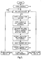
- the microprocessor 11 In operation ( Figure 5) the microprocessor 11 initially stores a threshold (step 18) for the banknotes to be fed. The apparatus then monitors for the arrival of a banknote by sensing the output of the photodiodes 6 (step 19). When a note is sensed, the outputs from the photodiodes 6 are regularly sampled (step 20), averaged and stored (step 21) in a memory of the microprocessor 11. A soil detection algorithm is then carried out. This algorithm assumes that the reflectance signal is sampled at fixed time intervals which represent fixed increments of distance along the document.
- the value of "n" is chosen at the time the system is configured for a particular document. A degree of control over the threshold value may be provided.
- the algorithm selects the lightest extended region of the document as being the most representative of the soiled state of the document, so as to match the type of analysis used by a human observer and also to minimise the effects of variation in the density of printing inks.
- the algorithm is as follows.
- FIG 4A shows the reason for positioning the photodiodes 6 and windows 7 in the locations shown in Figure 1.
- This shows the variation in intensity of reflected light with direction in accordance with the Lambertian Law.
- the direction of the incident light 9 is normal to the banknote 3.
- the variation in intensity of the remaining diffusely reflected light is generally symmetrical about the position 17 of the banknote 3 which is illuminated and about the region through which the specularly reflected radiation passes.
- the photodiodes 6 are positioned therefore at corresponding positions on each side of the line of symmetry.
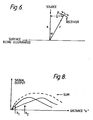
- Figure 4B (outside the present invention) illustrates another example in which the angle of illumination is indicated by an arrow 9a.
- the intensity of the surface illumination is arranged to be constant with variations of "a" (commonly achieved by collimation or focusing of the illumination) then the strength of the signal will be proportional to the following terms:
- FIG. 7 A family of curves derived from this equation is shown in Figure 7.
- Each of the curves uses a value for "b" of 10 mm and clearly shows a maximum at which the percentage variation of signal strength with variation of working distance is at a minimum.
- the curves become flatter as " ⁇ " is reduced, as shown, from 45° through 30° and 0° to -20°.
- All of the curves are for an unmasked sensor at the sensing position, apart from one in which the presence of the mask has given an effective value for " ⁇ " of 0°. In other words, the apertured mask is parallel to the surface under examination.
- the nominal working distance D between the housing 1 and the support 10 is set to correspond to a position at the centre of the plateau region of the curve for the chosen values of "b" and " ⁇ ". Thereafter, variations in the distance D during the feeding of the banknote 3 past the housing 1 will result in little change in the radiation received at each window 7.
- the windows 7 may be rectangular, and the illuminated area may be 10 mm by 2.5 mm.
- the or each of the sensing positions is situated at an angle of between +20° and -20° relatively to the surface 3, and/or at a separation distance "b" of between 10 mm and 17 mm perpendicularly to the beam of radiation 9 before diffuse reflection by the surface 3, for a working range of distances D of between 8 mm and 15 mm perpendicularly to the surface 3.
Landscapes
- Health & Medical Sciences (AREA)
- General Health & Medical Sciences (AREA)
- Toxicology (AREA)
- Physics & Mathematics (AREA)
- General Physics & Mathematics (AREA)
- Biochemistry (AREA)
- Chemical & Material Sciences (AREA)
- Analytical Chemistry (AREA)
- Life Sciences & Earth Sciences (AREA)
- Immunology (AREA)
- Pathology (AREA)
- Inspection Of Paper Currency And Valuable Securities (AREA)
- Investigating Or Analysing Materials By Optical Means (AREA)
- Investigating Materials By The Use Of Optical Means Adapted For Particular Applications (AREA)
- Image Processing (AREA)
- Image Analysis (AREA)
Claims (17)
- Verfahren zum Überwachen der Streureflexion eines Teils einer Oberfläche (3), wobei das Verfahren folgendes umfasst:
Exponieren des Oberflächenteils eines Strahlenbündels (9), das senkrecht zu der Oberfläche (3) ist;
Messen der Intensität eines Teils der Streustrahlung, die von dem Oberflächenteil reflektiert wird, an zwei Messorten, die so gelagert sind, dass die Intensität der gestreut reflektierten Strahlung, die an jedem Messort gemessen wird, im wesentlichen gegenüber Veränderungen in der Entfernung (D) des Messortes von dem Oberflächenteil innerhalb eines Arbeitsbereich der Entfernungen (D) unveränderlich ist; und
Bestimmen eines Wertes, der die Streureflexion des Oberflächenteils darstellt, von den gemessenen Intensitäten; wobei das Verfahren weiterhin folgendes umfasst:
Anordnen der Messorte in symmetrischen Stellungen auf jeder Seite des Strahlenbündels; und
Mitteln der an den Messorten gemessenen Intensitäten, um einen Streureflexionswert für den Oberflächenteil, der gegenüber Falten und Knicken in dem Oberflächenteil im wesentlichen unveränderlich ist, zu erhalten. - Verfahren nach Anspruch 1, das umfasst, entsprechende, mit Öffnungen versehene Masken zwischen zwei Strahlungsmessfühlern (6) und dem Oberflächenteil so anzuordnen, dass eine Öffnung (7) in jeder mit Öffnungen versehenen Maske an einem entsprechenden Messort angeordnet ist, und mit der anderen Öffnung in der anderen mit Öffnungen versehenen Maske koplanar ist.
- Verfahren nach einem der vorhergehenden Ansprüche, das umfasst, das Licht, das jeden Messort erreicht, zu filtern, um die Reaktion des Systems im wesentlichen an die Reaktion des menschlichen Auges anzupassen.
- Verfahren nach einem der vorhergehenden Ansprüche, das umfasst, die Schritte des Verfahrens an aufeinanderfolgenden Teilen der Oberfläche durchzuführen.
- Verfahren nach Anspruch 4, das umfasst, die von aufeinanderfolgenden Teilen der Oberfläche erhaltenen Werte zu speichern; n aufeinanderfolgende Werte zu addieren, beginnend mit dem ersten Wert; den Additionsschritt für Sätze von n Werten zu wiederholen, beginnend mit dem zweiten, dritten, vierten, usw. Wert, bis der letzte von der Oberfläche erhaltene Wert in einer Summe eingeschlossen ist; und das Maximum der Summen mit einem Grenzwert zu vergleichen, um festzustellen, ob der Verschmutzungszustand der Oberfläche annehmbar oder unannehmbar ist.
- Verfahren nach einem der vorhergehenden Ansprüche, worin das Strahlenbündel (9) weisses Licht umfasst.
- Verfahren nach einem der vorhergehenden Ansprüche, das umfasst, zu verursachen, dass dem Strahlenbündel (9) eine Bezugsoberfläche (8) exponiert wird, Streustrahlung, die von der Bezugsoberfläche an jedem Messort reflektiert wird, zu messen, um entsprechende Bezugswerte zu erzeugen, und nachfolgend die an jedem Messort gemessenen Intensitäten durch Vergleich mit den entsprechenden Bezugswerten zu normalisieren.
- Verfahren nach einem der vorhergehenden Ansprüche, worin die Oberfläche (3) durch ein Blatt definiert ist, wobei das Verfahren weiterhin umfasst, zu verursachen, dass sich das Blatt in eine von zwei Richtungen (13, 14) gemäss der Streureflexion eines Teils der Oberfläche bewegt.
- Vorrichtung zum Überwachen der Streureflexion einer Oberfläche, wobei die Vorrichtung folgendes umfasst:
eine Strahlenbündelquelle (2);
ein Oberflächentragglied (10), das so angebracht ist, dass die Strahlung während des Gebrauchs auf eine Oberfläche (3), die von dem Tragglied getragen wird und senkrecht zu der Oberfläche (3) ist, auftrifft; und
zwei Strahlungsmessfühler (6) zum Erzeugen entsprechender Signale zum Abgeben an Verarbeitungsmittel (11); wobei jedes Signal der Intensität eines Teils der Streustrahlung, die von der Oberfläche reflektiert wird und durch einen Messort geht, entspricht, und jeder Messort so gelagert ist, dass die Intensität der gestreut reflektierten Strahlung, die dort gemessen wird, im wesentlichen gegenüber Veränderungen in der Entfernung (D) der Messorte von dem Oberflächenteil in einem Arbeitsbereich der Entfernungen (D) unveränderlich ist;
wobei die Messorte an symmetrischen Stellen zu jeder Seite des Strahlenbündeles angeordnet sind; und
wobei die Vorrichtung weiterhin ein Mittel umfasst, um die entsprechenden Signale, die an den Messorten gemessen werden, zu mitteln, um einen Streureflexionswert für den Oberflächenteil, der im wesentlichen gegenüber Falten und Knicken in dem Oberflächenteil unveränderlich ist, zu erhalten. - Vorrichtung nach Anspruch 9, worin entsprechende mit Öffnungen versehene Masken zwischen zwei Strahlungsmessfühler (6) und die Oberfläche (3) gesetzt werden, so dass eine Öffnung (7) in jeder mit Öffnungen versehenen Maske an einem entsprechenden Messort gelagert ist und mit der anderen Öffnung in der anderen mit Öffnungen versehenen Maske koplanar ist.
- Vorrichtung nach Anspruch 9 oder Anspruch 10, worin ein Filter für jeden Messort vorhanden ist, um die Reaktion des Systems im wesentlichen der Reaktion des menschlichen Auges anzupassen.
- Vorrichtung nach einem der Ansprüche 9 bis 11, worin die Quelle Fokussierungsmittel (4) einschliesst, um das Strahlenbündel (9) auf einer von dem Tragglied (10) getragenen Oberfläche während des Gebrauchs zu fokussieren.
- Vorrichtung nach einem der Ansprüche 9 bis 12, worin wenigstens ein Teil des Traggliedes (10) relativ zu dem Strahlenbündel (9) und jedem Messort beweglich ist, wobei eine Reihe von Orten auf der Oberfläche abgetastet wird.
- Vorrichtung nach einem der Ansprüche 9 bis 13, worin eine Bezugsoberfläche (8), die beleuchtet wird, wenn keine Oberfläche (3) getragen wird, eine im wesentlichen gleichförmige Wiederspiegelung hat, wobei die an jedem Messort erhaltene Strahlung nach der Reflexion von der Oberfläche (8) benutzt wird, um einen Bezugswert festzusetzen.
- Vorrichtung nach Anspruch 14, worin die Bezugsoberfläche, die eine gleichförmige Wiederspiegelung hat, weisses Licht reflektiert.
- Vorrichtung nach einem der Ansprüche 9 bis 15, worin jeder Messort bei einem Winkel von zwischen +20° und -20° relativ zu der Oberfläche (3) gelagert ist, und/oder bei einer Trennung von zwischen 10 mm und 17 mm senkrecht zu dem Strahlenbündel (9) vor der Streureflexion durch die Oberfläche (3), für einen Arbeitsbereich von Entfernungen (D) von zwischen 8 mm und 15 mm senkrecht zu der Oberfläche (3).
- Blattzufuhrvorrichtung, die eine Überwachungsvorrichtung nach einem der Ansprüche 9 bis 16 umfasst, die weiterhin ein Transportiermittel (10) umfasst, wovon ein Teil das Tragglied (10) der Überwachungsvorrichtung umfasst, um einzelne Blätter (3) an dem Bereich, der bestrahlt wird, vorbei zu transportieren; wobei das Verarbeitungsmittel (11) mit jedem Messfühler (6) verbunden ist, um die Streureflexion der Oberfläche und um die Annehmbarkeit jedes Blattes (3) zu bestimmen; und eine Ableitungsvorrichtung (12), die in der Bahn des Blattes stromab von der Überwachungsvorrichtung angeordnet ist und von dem Verarbeitungsmittel (11) kontrolliert wird, um jedes Blatt in eine von zwei Richtungen zu leiten, je nach der Feststellung, ob das Blatt annehmbar oder unannehmbar ist.
Applications Claiming Priority (2)
| Application Number | Priority Date | Filing Date | Title |
|---|---|---|---|
| GB08616334A GB2193803A (en) | 1986-07-04 | 1986-07-04 | Monitoring diffuse reflectivity |
| GB8616334 | 1986-07-04 |
Publications (2)
| Publication Number | Publication Date |
|---|---|
| EP0257749A1 EP0257749A1 (de) | 1988-03-02 |
| EP0257749B1 true EP0257749B1 (de) | 1992-04-22 |
Family
ID=10600566
Family Applications (1)
| Application Number | Title | Priority Date | Filing Date |
|---|---|---|---|
| EP87305961A Expired - Lifetime EP0257749B1 (de) | 1986-07-04 | 1987-07-06 | Verfahren und Vorrichtung zur Messung der Streureflexion einer Oberfläche |
Country Status (7)
| Country | Link |
|---|---|
| US (1) | US4988206A (de) |
| EP (1) | EP0257749B1 (de) |
| JP (1) | JPH01500616A (de) |
| DE (1) | DE3778453D1 (de) |
| ES (1) | ES2031505T3 (de) |
| GB (1) | GB2193803A (de) |
| WO (1) | WO1988000338A1 (de) |
Families Citing this family (38)
| Publication number | Priority date | Publication date | Assignee | Title |
|---|---|---|---|---|
| JPH0365953U (de) * | 1989-10-30 | 1991-06-26 | ||
| JP2805909B2 (ja) * | 1989-11-10 | 1998-09-30 | 松下電器産業株式会社 | 電子部品のリードの計測装置及び計測方法 |
| WO1994016412A1 (en) * | 1993-01-09 | 1994-07-21 | Mars, Incorporated | Detection of counterfeit objects |
| EP0622762B1 (de) * | 1993-04-27 | 1998-07-01 | The Furukawa Electric Co., Ltd. | Vorrichtung zum Nachweis von Fluoreszenz |
| CA2179994A1 (en) * | 1994-01-04 | 1995-07-13 | John Geoffrey Hopwood | Detection of counterfeits objects, for instance counterfeits banknotes |
| US5918960A (en) * | 1994-01-04 | 1999-07-06 | Mars Incorporated | Detection of counterfeit objects, for instance counterfeit banknotes |
| NL9401796A (nl) * | 1994-10-28 | 1996-06-03 | Tno | Documentherkenningsinrichting. |
| US5982500A (en) * | 1995-05-07 | 1999-11-09 | Platsch; Hans Georg | Device for measuring the surface of a print product |
| NZ286314A (en) * | 1995-05-25 | 1998-07-28 | Machinery Dev Co Pty Ltd | Feed roller for compressive removal of bark from a felled tree comprising a base portion and projecting engaging means in a generally helical arrangement |
| US5966205A (en) | 1997-07-01 | 1999-10-12 | Lj Laboratories, Llc | Method and apparatus for detecting and preventing counterfeiting |
| US5759030A (en) | 1996-01-02 | 1998-06-02 | Lj Laboratories, L.L.C. | Method for determing optical characteristics of teeth |
| US6307629B1 (en) | 1997-08-12 | 2001-10-23 | Lj Laboratories, L.L.C. | Apparatus and method for measuring optical characteristics of an object |
| US6373573B1 (en) * | 2000-03-13 | 2002-04-16 | Lj Laboratories L.L.C. | Apparatus for measuring optical characteristics of a substrate and pigments applied thereto |
| US5745229A (en) * | 1996-01-02 | 1998-04-28 | Lj Laboratories, L.L.C. | Apparatus for determining optical characteristics of an object |
| US6254385B1 (en) | 1997-01-02 | 2001-07-03 | Lj Laboratories, Llc | Apparatus and method for measuring optical characteristics of teeth |
| US5926262A (en) * | 1997-07-01 | 1999-07-20 | Lj Laboratories, L.L.C. | Apparatus and method for measuring optical characteristics of an object |
| US6118521A (en) * | 1996-01-02 | 2000-09-12 | Lj Laboratories, L.L.C. | Apparatus and method for measuring optical characteristics of an object |
| US6239868B1 (en) | 1996-01-02 | 2001-05-29 | Lj Laboratories, L.L.C. | Apparatus and method for measuring optical characteristics of an object |
| US5880826A (en) | 1997-07-01 | 1999-03-09 | L J Laboratories, L.L.C. | Apparatus and method for measuring optical characteristics of teeth |
| US6233047B1 (en) | 1997-01-02 | 2001-05-15 | Lj Laboratories, L.L.C. | Apparatus and method for measuring optical characteristics of an object |
| US6301004B1 (en) * | 2000-05-31 | 2001-10-09 | Lj Laboratories, L.L.C. | Apparatus and method for measuring optical characteristics of an object |
| US6271913B1 (en) | 1997-07-01 | 2001-08-07 | Lj Laboratories, Llc | Apparatus and method for measuring optical characteristics of an object |
| US6501542B2 (en) * | 1998-06-30 | 2002-12-31 | Lj Laboratories, Llc | Apparatus and method for measuring optical characteristics of an object |
| US6449041B1 (en) | 1997-07-01 | 2002-09-10 | Lj Laboratories, Llc | Apparatus and method for measuring optical characteristics of an object |
| US6870616B2 (en) * | 1998-06-30 | 2005-03-22 | Jjl Technologies Llc | Spectrometer apparatus for determining an optical characteristic of an object or material having one or more sensors for determining a physical position or non-color property |
| GB9715084D0 (en) * | 1997-07-18 | 1997-09-24 | Ncr Int Inc | An apparatus for validating sheets |
| US6246479B1 (en) | 1998-06-08 | 2001-06-12 | Lj Laboratories, L.L.C. | Integrated spectrometer assembly and methods |
| US6246471B1 (en) | 1998-06-08 | 2001-06-12 | Lj Laboratories, Llc | Apparatus and method for measuring optical characteristics of an object |
| US6573984B2 (en) * | 1998-06-30 | 2003-06-03 | Lj Laboratories Llc | Apparatus and method for measuring optical characteristics of teeth |
| US6249348B1 (en) | 1998-11-23 | 2001-06-19 | Lj Laboratories, L.L.C. | Integrated spectrometer assembly and methods |
| US6538726B2 (en) | 1998-07-10 | 2003-03-25 | Lj Laboratories, Llc | Apparatus and method for measuring optical characteristics of an object |
| WO2001009588A1 (en) * | 1999-07-30 | 2001-02-08 | Umm Electronics Inc. | Method and apparatus to reduce reflectance errors due to non-uniform color development |
| US6362888B1 (en) | 1999-12-23 | 2002-03-26 | Lj Laboratories, L.L.C. | Spectrometer assembly |
| US6519037B2 (en) | 1999-12-23 | 2003-02-11 | Lj Laboratories, Llc | Spectrometer having optical unit including a randomized fiber optic implement |
| US6414750B2 (en) | 2000-01-10 | 2002-07-02 | Lj Laboratories, L.L.C. | Spectrometric apparatus and method for measuring optical characteristics of an object |
| EP1321904B2 (de) † | 2001-12-20 | 2020-04-08 | Crane Payment Innovations, Inc. | Vorrichtung zur Erfassung von optischen Eigenschaften eines Geldscheins |
| US6903813B2 (en) | 2002-02-21 | 2005-06-07 | Jjl Technologies Llc | Miniaturized system and method for measuring optical characteristics |
| JP4033781B2 (ja) * | 2002-05-29 | 2008-01-16 | シャープ株式会社 | 光学式物体識別装置および処理システムおよび搬送処理システム |
Citations (2)
| Publication number | Priority date | Publication date | Assignee | Title |
|---|---|---|---|---|
| GB2059054A (en) * | 1979-09-13 | 1981-04-15 | Oreal | Process and apparatus for making a numerical determination of the colour or of a colour change of an object |
| EP0234579A2 (de) * | 1986-02-26 | 1987-09-02 | Fuji Photo Film Co., Ltd. | Reflektometer |
Family Cites Families (16)
| Publication number | Priority date | Publication date | Assignee | Title |
|---|---|---|---|---|
| GB1053386A (de) * | 1900-01-01 | |||
| GB894570A (en) * | 1959-07-15 | 1962-04-26 | British Iron Steel Research | Improvements in or relating to the detection of surface abnormalities |
| US3526777A (en) * | 1968-04-25 | 1970-09-01 | Hunter Associates Lab Inc | Reflectance measuring apparatus including a mask for compensating for movement of the specimen |
| US3718399A (en) * | 1971-06-29 | 1973-02-27 | G Kalman | Distance compensated reflectance sensor |
| US3984189A (en) * | 1973-01-19 | 1976-10-05 | Hitachi Electronics, Ltd. | Method and apparatus for detecting defects in a surface regardless of surface finish |
| US4092068A (en) * | 1976-05-05 | 1978-05-30 | Domtar Inc. | Surface sensor |
| AT349248B (de) * | 1976-11-29 | 1979-03-26 | Gao Ges Automation Org | Verfahren zur dynamischen messung des verschmutzungsgrades von banknoten und pruefvorrichtung zur durchfuehrung dieses verfahrens |
| US4252443A (en) * | 1979-08-09 | 1981-02-24 | Domtar Inc. | Blackening sensor |
| JPS56148041A (en) * | 1980-04-18 | 1981-11-17 | Fujitsu General Ltd | Reflected light quantity detector |
| US4583861A (en) * | 1981-08-12 | 1986-04-22 | Tokyo Shibaura Denki Kabushiki Kaisha | Surface condition judging apparatus |
| GB2117897B (en) * | 1982-03-03 | 1986-04-16 | Sira Ltd | Detecting surface defects |
| HU188795B (en) * | 1982-05-28 | 1986-05-28 | Koezponti Elelmiszeripari Kutato Intezet,Hu | Detecting arrangement for meassuring the intensity of radiation scattering at a given angle from a sample exposed to radiation of given angle of incidence |
| DE3226372A1 (de) * | 1982-07-14 | 1984-01-19 | Compur-Electronic GmbH, 8000 München | Verfahren und vorrichtung zum messen von remissionen |
| DE3226370A1 (de) * | 1982-07-14 | 1984-01-19 | Compur-Electronic GmbH, 8000 München | Remissionsmesskopf |
| JPS60149948A (ja) * | 1984-01-18 | 1985-08-07 | Yaskawa Electric Mfg Co Ltd | 濃度検出装置 |
| DE3526553A1 (de) * | 1985-07-25 | 1987-01-29 | Zeiss Carl Fa | Remissionsmessgeraet zur beruehrungslosen messung |
-
1986
- 1986-07-04 GB GB08616334A patent/GB2193803A/en not_active Withdrawn
-
1987
- 1987-07-06 EP EP87305961A patent/EP0257749B1/de not_active Expired - Lifetime
- 1987-07-06 JP JP62503994A patent/JPH01500616A/ja active Pending
- 1987-07-06 ES ES198787305961T patent/ES2031505T3/es not_active Expired - Lifetime
- 1987-07-06 WO PCT/GB1987/000474 patent/WO1988000338A1/en not_active Ceased
- 1987-07-06 US US07/165,196 patent/US4988206A/en not_active Expired - Fee Related
- 1987-07-06 DE DE8787305961T patent/DE3778453D1/de not_active Expired - Lifetime
Patent Citations (2)
| Publication number | Priority date | Publication date | Assignee | Title |
|---|---|---|---|---|
| GB2059054A (en) * | 1979-09-13 | 1981-04-15 | Oreal | Process and apparatus for making a numerical determination of the colour or of a colour change of an object |
| EP0234579A2 (de) * | 1986-02-26 | 1987-09-02 | Fuji Photo Film Co., Ltd. | Reflektometer |
Also Published As
| Publication number | Publication date |
|---|---|
| GB8616334D0 (en) | 1986-08-13 |
| GB2193803A (en) | 1988-02-17 |
| ES2031505T3 (es) | 1992-12-16 |
| DE3778453D1 (de) | 1992-05-27 |
| US4988206A (en) | 1991-01-29 |
| WO1988000338A1 (en) | 1988-01-14 |
| EP0257749A1 (de) | 1988-03-02 |
| JPH01500616A (ja) | 1989-03-01 |
Similar Documents
| Publication | Publication Date | Title |
|---|---|---|
| US4988206A (en) | Methods are apparatus for monitoring the diffuse reflectivity of a surface | |
| US5034616A (en) | Device for optically scanning sheet-like documents | |
| EP0072236B1 (de) | Gerät zur Feststellung von Klebeband auf Dokumenten | |
| EP1674859A1 (de) | Different-kind-of-object detektor unter einsatz eines ebenen-spektrometers | |
| US6242755B1 (en) | Method and device for the contactless measuring of strand-like textile material | |
| JPH09510548A (ja) | 包装材の皺線位置の検出方法および装置 | |
| US20030042438A1 (en) | Methods and apparatus for sensing degree of soiling of currency, and the presence of foreign material | |
| RU95117090A (ru) | Обнаружение поддельных объектов | |
| JP2002510102A (ja) | 物品を検査するための方法及び装置 | |
| RU2332718C2 (ru) | Способ анализа пачки плоских предметов | |
| EP0374799B1 (de) | Gerät zum Detektieren einer Anzahl Packungen in einem Bündel | |
| US5932888A (en) | Web or sheet edge position measurement process and device | |
| WO1999049277A1 (en) | An optical sensor system for incorporation in a conveyor system and a method for determining the geometry and/or angular position of a moving object | |
| EP0766817A1 (de) | Lichtstrommessung der partikelverunreinigung | |
| JP3604549B2 (ja) | 紙葉類の異物判別装置 | |
| EP0018505B1 (de) | Apparat zur Überwachung des Zustandes von Banknoten | |
| EP0244092B1 (de) | Optische Vorrichtung und Verfahren zur Untersuchung eines Gegenstandes | |
| RU2271576C2 (ru) | Способ определения подлинности банкнот и устройство для его осуществления | |
| EP0408337A1 (de) | Verfahren und Vorrichtung zur Überwachung eines Blattes | |
| US6257389B1 (en) | Device for examining securities | |
| JP3224083B2 (ja) | 板ガラスの欠点検出方法およびその装置 | |
| RU35455U1 (ru) | Устройство для определения подлинности банкнот | |
| JP5082552B2 (ja) | 光学的測定装置及び光学的測定方法 | |
| JPH0579996A (ja) | 付着物判別装置 | |
| JPH05188004A (ja) | 異物検出装置 |
Legal Events
| Date | Code | Title | Description |
|---|---|---|---|
| PUAI | Public reference made under article 153(3) epc to a published international application that has entered the european phase |
Free format text: ORIGINAL CODE: 0009012 |
|
| AK | Designated contracting states |
Kind code of ref document: A1 Designated state(s): DE ES GB IT SE |
|
| 17P | Request for examination filed |
Effective date: 19880901 |
|
| 17Q | First examination report despatched |
Effective date: 19900522 |
|
| GRAA | (expected) grant |
Free format text: ORIGINAL CODE: 0009210 |
|
| AK | Designated contracting states |
Kind code of ref document: B1 Designated state(s): DE ES GB IT SE |
|
| PG25 | Lapsed in a contracting state [announced via postgrant information from national office to epo] |
Ref country code: SE Effective date: 19920422 |
|
| REF | Corresponds to: |
Ref document number: 3778453 Country of ref document: DE Date of ref document: 19920527 |
|
| ITF | It: translation for a ep patent filed | ||
| REG | Reference to a national code |
Ref country code: ES Ref legal event code: FG2A Ref document number: 2031505 Country of ref document: ES Kind code of ref document: T3 |
|
| PLBI | Opposition filed |
Free format text: ORIGINAL CODE: 0009260 |
|
| 26 | Opposition filed |
Opponent name: GAO GESELLSCHAFT FUER AUTOMATION UND ORGANISATION Effective date: 19930122 |
|
| PGFP | Annual fee paid to national office [announced via postgrant information from national office to epo] |
Ref country code: ES Payment date: 19930701 Year of fee payment: 7 |
|
| PLAB | Opposition data, opponent's data or that of the opponent's representative modified |
Free format text: ORIGINAL CODE: 0009299OPPO |
|
| R26 | Opposition filed (corrected) |
Opponent name: GAO GESELLSCHAFT FUER AUTOMATION UND ORGANISATION Effective date: 19930122 |
|
| PG25 | Lapsed in a contracting state [announced via postgrant information from national office to epo] |
Ref country code: ES Free format text: LAPSE BECAUSE OF NON-PAYMENT OF DUE FEES Effective date: 19940707 |
|
| PGFP | Annual fee paid to national office [announced via postgrant information from national office to epo] |
Ref country code: DE Payment date: 19970714 Year of fee payment: 11 |
|
| RDAH | Patent revoked |
Free format text: ORIGINAL CODE: EPIDOS REVO |
|
| PGFP | Annual fee paid to national office [announced via postgrant information from national office to epo] |
Ref country code: GB Payment date: 19980629 Year of fee payment: 12 |
|
| RDAG | Patent revoked |
Free format text: ORIGINAL CODE: 0009271 |
|
| STAA | Information on the status of an ep patent application or granted ep patent |
Free format text: STATUS: PATENT REVOKED |
|
| 27W | Patent revoked |
Effective date: 19980312 |
|
| GBPR | Gb: patent revoked under art. 102 of the ep convention designating the uk as contracting state |
Free format text: 980312 |