EP0257832A2 - Pointe de sonde télescopique - Google Patents
Pointe de sonde télescopique Download PDFInfo
- Publication number
- EP0257832A2 EP0257832A2 EP87306811A EP87306811A EP0257832A2 EP 0257832 A2 EP0257832 A2 EP 0257832A2 EP 87306811 A EP87306811 A EP 87306811A EP 87306811 A EP87306811 A EP 87306811A EP 0257832 A2 EP0257832 A2 EP 0257832A2
- Authority
- EP
- European Patent Office
- Prior art keywords
- probe
- circuit
- pin
- circuit element
- transmission line
- Prior art date
- Legal status (The legal status is an assumption and is not a legal conclusion. Google has not performed a legal analysis and makes no representation as to the accuracy of the status listed.)
- Withdrawn
Links
Images

Classifications
-
- G—PHYSICS
- G01—MEASURING; TESTING
- G01R—MEASURING ELECTRIC VARIABLES; MEASURING MAGNETIC VARIABLES
- G01R1/00—Details of instruments or arrangements of the types included in groups G01R5/00 - G01R13/00 and G01R31/00
- G01R1/02—General constructional details
- G01R1/06—Measuring leads; Measuring probes
- G01R1/067—Measuring probes
- G01R1/073—Multiple probes
-
- G—PHYSICS
- G01—MEASURING; TESTING
- G01R—MEASURING ELECTRIC VARIABLES; MEASURING MAGNETIC VARIABLES
- G01R1/00—Details of instruments or arrangements of the types included in groups G01R5/00 - G01R13/00 and G01R31/00
- G01R1/02—General constructional details
- G01R1/06—Measuring leads; Measuring probes
- G01R1/067—Measuring probes
- G01R1/06766—Input circuits therefor
-
- H—ELECTRICITY
- H01—ELECTRIC ELEMENTS
- H01R—ELECTRICALLY-CONDUCTIVE CONNECTIONS; STRUCTURAL ASSOCIATIONS OF A PLURALITY OF MUTUALLY-INSULATED ELECTRICAL CONNECTING ELEMENTS; COUPLING DEVICES; CURRENT COLLECTORS
- H01R11/00—Individual connecting elements providing two or more spaced connecting locations for conductive members which are, or may be, thereby interconnected, e.g. end pieces for wires or cables supported by the wire or cable and having means for facilitating electrical connection to some other wire, terminal, or conductive member, blocks of binding posts
- H01R11/11—End pieces or tapping pieces for wires, supported by the wire and for facilitating electrical connection to some other wire, terminal or conductive member
- H01R11/18—End pieces terminating in a probe
Definitions
- the following invention relates to a spring loaded, telescoping electrical contact pin probe having a high input impedance and a wide band frequency response characteristic which can be mounted on a conventional "bed of nails” test fixture.
- Telescoping pin probes are commonly in use as test probes for printed circuits or other components.
- a telescoping pin is a telescoping rod mounted in a spring loaded sleeve and having a contact point for touching various desired locations on a printed circuit board.
- a number of telescoping pins are placed in a test fixture in an array or matrix.
- Such fixtures are commonly known in the industry as "bed of nails” test fixtures because of the use of a plurality of conical tipped probes held upright in the test fixture and placed relatively close together.
- a device under test such as a printed circuit board is placed in a chuck and lowered onto the test fixture until the probes make contact with the desired points on the circuit.
- the probes are connected by cables or transmission lines to a test instrument which then performs a series of diagnostic tests.
- probes of this type are DC, uncontrolled impedance probes.
- the pencil-thin shape of such probes which allows them to be placed in test fixtures of the type described above, prevents the use of active circuitry near the tip of the probe.
- Active probes have been available only in hand-held units which are considerably bulkier than the telescoping pin probes used in a test fixture. Therefore, the previously available test fixture probes are capable only of DC or very low frequency measurement and also have a low impedance input characteristic which may place undesirable loads on the circuit under test.
- the present invention comprises a telescoping pin probe including a telescoping pin which is held within an insulating sleeve, and a circuit element, also held within the sleeve and electrically connected to the telescoping pin.
- the circuit element is connected to a transmission line which is connected to an auxiliary electrical circuit for providing the telescoping pin with a high input impedance and a wide band frequency response characteristic.
- the telescoping pin probe of the invention may utilize a thin, elongate hybrid circuit mounted on a substrate and having an input at one end of the substrate and an output at the opposite end. Electrical contact between the telescoping pin and the hybrid circuit, and between the hybrid circuit and the transmission line is provided by conductive elastomers affixed to the input and output ends of the hybrid integrated circuit.
- the entire assembly may be fitted within an outer conductive sleeve which may be placed within a conventional telescoping pin test fixture.
- the outer sleeve may be connected to a ground plane, and the ground plane may, in turn, be connected to another telescoping pin which makes contact with a region of ground potential in the device under test.
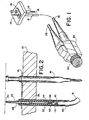
- a test fixture 10 includes a telescoping pin probe 12 and a ground probe 14.
- the ground probe 14 is connected to the telescoping pin probe 12 by a ground plane 16 which is situated on the surface of the test fixture 10.
- a coaxial cable 18 serves as a transmission line to connect the telescoping pin probe 12 to a compensation box 20 which houses active circuitry for providing the telescoping pin probe 12 with the required electrical characteristics.
- the compensation box 20 is powered by a power input line 22 which may be connected to any suitable power supply.
- the compensation box 20 includes a BNC connector 24 for connecting the compensation box 20 to the input of an electronic test instrument.
- the telescoping pin probe 12 includes a telescoping pin 26 comprising a spring loaded sheath 28 and a sharpened contact point 30.
- the telescoping pin 26 is held inside an insulator 32.
- a circuit element 34 which may be an RC attenuator is also held within insulating sleeve 32 and is connected to the spring loaded sheath 28 of the telescoping pin 26 by a small wad of conductive elastomer 36.
- the output of the circuit element 34 is connected by another small wad of conductive elastomer 38 to the signal path 40 of a transmission line 18.
- the transmission line 18 also includes a coaxial ground shield 42 which is brought into electrical contact with a metal receptacle 44 held within the test fixture 10.
- the metal receptacle 44 is connected to a ground plane 16 which is in turn connected to ground telescoping pin 14.
- the circuit element 34 may be a hybrid circuit printed on a thin elongate piece of alumina substrate.
- the circuit 34 may comprise a resistor R1 and capacitor C1 connected in parallel, which combine with the impedance provided by coaxial cable 18 and the circuit elements in active compensation box 20 to give the probe its characteristically high impedance and wide bandwidth frequency response.
- the telescoping pin 12 has a characteristically inductive tip as shown by inductor Lp.
- the circuit element 34 reduces the signal level encountered at the probe tip, acting as one half of a voltage divider.
- the other half of the voltage divider comprises a variable capacitor C2 and resistor R2.
- the two aforementioned portions of the voltage divider are linked by a high impedance cable 22 which has a nominal impedance of 120 ohms.
- the signal conductor of the cable 22 terminates in a damping resistor R4 and in a compensating peaking resistor R3.
- the voltage divider output is applied to the gate of high input impedance FET Q1.
- Q2 provides a current source for Q1 and thermally compensates for the heating of the FETS Q1 and Q2.
- the current gain of the attenuated probe tip signal is provided by Q4.
- Thermal compensation for Q4 is provided by Q3.
- the output of the amplifier comprising Q1, Q2, Q3 and Q4 is connected to a back termination network comprising R12, a 50 ohm resistor, connected in parallel with R13 and C4 in one branch and C3 in another branch.
- R13 and C4 compensate for skin effect losses which may occur in 50 ohm transmission line 46 at high frequencies.
- C3 provides a high frequency bypass to sharpen the leading edges of signal pulses to compensate for the initial capacitance presented by cable 46.
- Cable 46 is a standard 50 ohm cable which is connected to a test instrument 48.
- the test instrument 48 need not be connected directly to the compensation box 20 but may be located remotely from it and connected by a cable 46.
- the transmission line 22, whose impedence must be high in order for the attenuator located on circuit element 34 to function properly, is long enough to provide ample clearance for the probe 12 so that it may be located in the test fixture 10.
- the transmission line 22 does not, however, provide the link by which the compensation box 20 is connected to the test instrument. Rather, it is the back termination network that provides the compensation box 20 with the capability of driving the conventional 50 ohm cable 46, which may be of any arbitrary length.
Landscapes
- Physics & Mathematics (AREA)
- General Physics & Mathematics (AREA)
- Measuring Leads Or Probes (AREA)
- Tests Of Electronic Circuits (AREA)
Applications Claiming Priority (2)
| Application Number | Priority Date | Filing Date | Title |
|---|---|---|---|
| US06/891,834 US4739259A (en) | 1986-08-01 | 1986-08-01 | Telescoping pin probe |
| US891834 | 1992-06-01 |
Publications (2)
| Publication Number | Publication Date |
|---|---|
| EP0257832A2 true EP0257832A2 (fr) | 1988-03-02 |
| EP0257832A3 EP0257832A3 (fr) | 1989-12-27 |
Family
ID=25398904
Family Applications (1)
| Application Number | Title | Priority Date | Filing Date |
|---|---|---|---|
| EP87306811A Withdrawn EP0257832A3 (fr) | 1986-08-01 | 1987-07-31 | Pointe de sonde télescopique |
Country Status (3)
| Country | Link |
|---|---|
| US (1) | US4739259A (fr) |
| EP (1) | EP0257832A3 (fr) |
| JP (1) | JPS6338166A (fr) |
Cited By (3)
| Publication number | Priority date | Publication date | Assignee | Title |
|---|---|---|---|---|
| EP0361689B1 (fr) * | 1988-09-09 | 1995-07-19 | Qa Technology Company Inc. | Capteur pour tester des circuits électriques |
| WO2005045448A1 (fr) * | 2003-10-14 | 2005-05-19 | The Ludlow Compagny Lp | Terminal de cable a chevilles de contact comprenant un composant electrique |
| US7371128B2 (en) | 2003-10-14 | 2008-05-13 | Precision Interconnect, Inc. | Cable terminal with air-enhanced contact pins |
Families Citing this family (59)
| Publication number | Priority date | Publication date | Assignee | Title |
|---|---|---|---|---|
| JPH0194277A (ja) * | 1987-10-06 | 1989-04-12 | Furuno Electric Co Ltd | 回路基板検査装置 |
| US5006793A (en) * | 1989-06-08 | 1991-04-09 | Cascade Microtech, Inc. | High-frequency active probe having replaceable contact needles |
| US5304921A (en) * | 1991-08-07 | 1994-04-19 | Hewlett-Packard Company | Enhanced grounding system for short-wire lengthed fixture |
| US5175493A (en) * | 1991-10-11 | 1992-12-29 | Interconnect Devices, Inc. | Shielded electrical contact spring probe assembly |
| US6380751B2 (en) | 1992-06-11 | 2002-04-30 | Cascade Microtech, Inc. | Wafer probe station having environment control enclosure |
| US5345170A (en) | 1992-06-11 | 1994-09-06 | Cascade Microtech, Inc. | Wafer probe station having integrated guarding, Kelvin connection and shielding systems |
| US5308250A (en) * | 1992-10-30 | 1994-05-03 | Hewlett-Packard Company | Pressure contact for connecting a coaxial shield to a microstrip ground plane |
| US7368924B2 (en) * | 1993-04-30 | 2008-05-06 | International Business Machines Corporation | Probe structure having a plurality of discrete insulated probe tips projecting from a support surface, apparatus for use thereof and methods of fabrication thereof |
| US6452406B1 (en) * | 1996-09-13 | 2002-09-17 | International Business Machines Corporation | Probe structure having a plurality of discrete insulated probe tips |
| US5561377A (en) | 1995-04-14 | 1996-10-01 | Cascade Microtech, Inc. | System for evaluating probing networks |
| US6232789B1 (en) | 1997-05-28 | 2001-05-15 | Cascade Microtech, Inc. | Probe holder for low current measurements |
| US6002263A (en) | 1997-06-06 | 1999-12-14 | Cascade Microtech, Inc. | Probe station having inner and outer shielding |
| US6172514B1 (en) * | 1999-03-12 | 2001-01-09 | Lucent Technologies Inc. | Test probe retainer |
| US6414504B2 (en) * | 1999-05-20 | 2002-07-02 | Delaware Capital Formation, Inc. | Coaxial tilt pin fixture for testing high frequency circuit boards |
| US6445202B1 (en) | 1999-06-30 | 2002-09-03 | Cascade Microtech, Inc. | Probe station thermal chuck with shielding for capacitive current |
| US6798229B2 (en) * | 2000-05-11 | 2004-09-28 | Brian D. Butler | Wide-bandwidth coaxial probe |
| US6400167B1 (en) * | 2000-08-21 | 2002-06-04 | Tektronix, Inc. | Probe tip adapter for a measurement probe |
| US6331836B1 (en) * | 2000-08-24 | 2001-12-18 | Fast Location.Net, Llc | Method and apparatus for rapidly estimating the doppler-error and other receiver frequency errors of global positioning system satellite signals weakened by obstructions in the signal path |
| US6965226B2 (en) | 2000-09-05 | 2005-11-15 | Cascade Microtech, Inc. | Chuck for holding a device under test |
| US6914423B2 (en) | 2000-09-05 | 2005-07-05 | Cascade Microtech, Inc. | Probe station |
| DE10143173A1 (de) | 2000-12-04 | 2002-06-06 | Cascade Microtech Inc | Wafersonde |
| US6459287B1 (en) * | 2001-05-18 | 2002-10-01 | Tektronix, Inc. | Attachable/detachable probing point |
| WO2003020467A1 (fr) | 2001-08-31 | 2003-03-13 | Cascade Microtech, Inc. | Appareil de test optique |
| US6777964B2 (en) | 2002-01-25 | 2004-08-17 | Cascade Microtech, Inc. | Probe station |
| ATE371196T1 (de) * | 2002-03-05 | 2007-09-15 | Rika Denshi America Inc | Vorrichtung für eine schnittstelle zwischen elektronischen gehäusen und testgeräten |
| JP2005527823A (ja) | 2002-05-23 | 2005-09-15 | カスケード マイクロテック インコーポレイテッド | デバイスのテスト用プローブ |
| US6847219B1 (en) | 2002-11-08 | 2005-01-25 | Cascade Microtech, Inc. | Probe station with low noise characteristics |
| US6724205B1 (en) | 2002-11-13 | 2004-04-20 | Cascade Microtech, Inc. | Probe for combined signals |
| US7250779B2 (en) | 2002-11-25 | 2007-07-31 | Cascade Microtech, Inc. | Probe station with low inductance path |
| US6861856B2 (en) | 2002-12-13 | 2005-03-01 | Cascade Microtech, Inc. | Guarded tub enclosure |
| US7221172B2 (en) | 2003-05-06 | 2007-05-22 | Cascade Microtech, Inc. | Switched suspended conductor and connection |
| US7492172B2 (en) | 2003-05-23 | 2009-02-17 | Cascade Microtech, Inc. | Chuck for holding a device under test |
| US7057404B2 (en) | 2003-05-23 | 2006-06-06 | Sharp Laboratories Of America, Inc. | Shielded probe for testing a device under test |
| US7250626B2 (en) | 2003-10-22 | 2007-07-31 | Cascade Microtech, Inc. | Probe testing structure |
| DE202004021093U1 (de) | 2003-12-24 | 2006-09-28 | Cascade Microtech, Inc., Beaverton | Aktiver Halbleiterscheibenmessfühler |
| US7187188B2 (en) | 2003-12-24 | 2007-03-06 | Cascade Microtech, Inc. | Chuck with integrated wafer support |
| JP2008502167A (ja) | 2004-06-07 | 2008-01-24 | カスケード マイクロテック インコーポレイテッド | 熱光学チャック |
| US7330041B2 (en) | 2004-06-14 | 2008-02-12 | Cascade Microtech, Inc. | Localizing a temperature of a device for testing |
| KR20070058522A (ko) | 2004-09-13 | 2007-06-08 | 캐스케이드 마이크로테크 인코포레이티드 | 양측 프루빙 구조 |
| US7656172B2 (en) | 2005-01-31 | 2010-02-02 | Cascade Microtech, Inc. | System for testing semiconductors |
| US7535247B2 (en) | 2005-01-31 | 2009-05-19 | Cascade Microtech, Inc. | Interface for testing semiconductors |
| US20060267605A1 (en) * | 2005-05-27 | 2006-11-30 | Yang Kei-Wean C | Differential measurement probe having a ground clip system for the probing tips |
| US7242202B2 (en) * | 2005-05-31 | 2007-07-10 | Agilent Technologies, Inc. | Signal probe and probe assembly |
| US7449899B2 (en) | 2005-06-08 | 2008-11-11 | Cascade Microtech, Inc. | Probe for high frequency signals |
| JP5080459B2 (ja) | 2005-06-13 | 2012-11-21 | カスケード マイクロテック インコーポレイテッド | 広帯域能動/受動差動信号プローブ |
| JP2007048491A (ja) * | 2005-08-08 | 2007-02-22 | D D K Ltd | 電気コネクタ |
| DE202007018733U1 (de) | 2006-06-09 | 2009-03-26 | Cascade Microtech, Inc., Beaverton | Messfühler für differentielle Signale mit integrierter Symmetrieschaltung |
| US7443186B2 (en) | 2006-06-12 | 2008-10-28 | Cascade Microtech, Inc. | On-wafer test structures for differential signals |
| US7723999B2 (en) | 2006-06-12 | 2010-05-25 | Cascade Microtech, Inc. | Calibration structures for differential signal probing |
| US7764072B2 (en) | 2006-06-12 | 2010-07-27 | Cascade Microtech, Inc. | Differential signal probing system |
| US7403028B2 (en) | 2006-06-12 | 2008-07-22 | Cascade Microtech, Inc. | Test structure and probe for differential signals |
| DE102006052748A1 (de) * | 2006-08-14 | 2008-04-30 | Rohde & Schwarz Gmbh & Co. Kg | Oszilloskop-Tastkopf |
| US7724009B2 (en) * | 2007-02-09 | 2010-05-25 | Mpi Corporation | Method of making high-frequency probe, probe card using the high-frequency probe |
| US7876114B2 (en) | 2007-08-08 | 2011-01-25 | Cascade Microtech, Inc. | Differential waveguide probe |
| US8319503B2 (en) * | 2008-11-24 | 2012-11-27 | Cascade Microtech, Inc. | Test apparatus for measuring a characteristic of a device under test |
| US20120182034A1 (en) * | 2011-01-17 | 2012-07-19 | 3M Innovative Properties Company | Contact assembly |
| US10585118B2 (en) * | 2017-05-10 | 2020-03-10 | Tektronix, Inc. | Wide range compensation of low frequency response passive probe |
| US10908183B2 (en) * | 2017-11-06 | 2021-02-02 | National Instruments Corporation | Active probe powered through driven coax cable |
| CN115469203B (zh) * | 2022-09-05 | 2023-09-19 | 上海泽丰半导体科技有限公司 | 一种探针卡行程测量系统和方法 |
Family Cites Families (13)
| Publication number | Priority date | Publication date | Assignee | Title |
|---|---|---|---|---|
| US2849681A (en) * | 1955-12-21 | 1958-08-26 | Prec Apparatus Co Inc | Electrical probe |
| US2883619A (en) * | 1956-02-29 | 1959-04-21 | Tektronix Inc | Electrical probe |
| US3870978A (en) * | 1973-09-13 | 1975-03-11 | Omni Spectra Inc | Abutting electrical contact means using resilient conductive material |
| CA1038042A (fr) * | 1975-03-03 | 1978-09-05 | Motorola | Sonde programmable et mode de convexion des unites a l'essai et du materiel d'essai |
| US4051432A (en) * | 1976-08-02 | 1977-09-27 | Canadian Patents & Development Limited | Attenuator for measuring high voltage fast rise time pulses |
| US4210863A (en) * | 1977-03-28 | 1980-07-01 | Huntron Instruments, Inc. | Extendible probe for use with test instruments |
| JPS5915376B2 (ja) * | 1977-10-18 | 1984-04-09 | 信越ポリマ−株式会社 | 電子回路部品 |
| US4418314A (en) * | 1980-10-20 | 1983-11-29 | The United States Of America As Represented By The Secretary Of The Army | High impedance fast voltage probe |
| DE3108523A1 (de) * | 1981-03-06 | 1982-09-23 | Feinmetall Gmbh, 7033 Herrenberg | Kontaktvorrichtung |
| JPS5848194A (ja) * | 1981-09-18 | 1983-03-22 | ニツタン株式会社 | 火災感知器のアドレス符号送受信回路 |
| GB2125236A (en) * | 1982-08-11 | 1984-02-29 | Tektronix Inc | Stress-isolating electrical connections |
| JPH068826B2 (ja) * | 1984-09-07 | 1994-02-02 | ヒューレット・パッカード・カンパニー | プローブ回路 |
| JPS6177286A (ja) * | 1984-09-21 | 1986-04-19 | インタ−ナショナル ビジネス マシ−ンズ コ−ポレ−ション | 同軸ケーブル用インターフェース装置 |
-
1986
- 1986-08-01 US US06/891,834 patent/US4739259A/en not_active Expired - Fee Related
-
1987
- 1987-07-30 JP JP62191478A patent/JPS6338166A/ja active Pending
- 1987-07-31 EP EP87306811A patent/EP0257832A3/fr not_active Withdrawn
Cited By (4)
| Publication number | Priority date | Publication date | Assignee | Title |
|---|---|---|---|---|
| EP0361689B1 (fr) * | 1988-09-09 | 1995-07-19 | Qa Technology Company Inc. | Capteur pour tester des circuits électriques |
| WO2005045448A1 (fr) * | 2003-10-14 | 2005-05-19 | The Ludlow Compagny Lp | Terminal de cable a chevilles de contact comprenant un composant electrique |
| US7364474B2 (en) | 2003-10-14 | 2008-04-29 | Precision Interconnect, Inc. | Cable terminal with contact pins including electrical component |
| US7371128B2 (en) | 2003-10-14 | 2008-05-13 | Precision Interconnect, Inc. | Cable terminal with air-enhanced contact pins |
Also Published As
| Publication number | Publication date |
|---|---|
| EP0257832A3 (fr) | 1989-12-27 |
| US4739259A (en) | 1988-04-19 |
| JPS6338166A (ja) | 1988-02-18 |
Similar Documents
| Publication | Publication Date | Title |
|---|---|---|
| EP0257832A2 (fr) | Pointe de sonde télescopique | |
| US5565788A (en) | Coaxial wafer probe with tip shielding | |
| US7205784B2 (en) | Probe for combined signals | |
| US4783625A (en) | Wideband high impedance card mountable probe | |
| US5477159A (en) | Integrated circuit probe fixture with detachable high frequency probe carrier | |
| US4418314A (en) | High impedance fast voltage probe | |
| US4740746A (en) | Controlled impedance microcircuit probe | |
| US6768328B2 (en) | Single point probe structure and method | |
| CA1271848A (fr) | Sonde de plaquette | |
| US5308250A (en) | Pressure contact for connecting a coaxial shield to a microstrip ground plane | |
| US6545483B1 (en) | Analyzer sensor | |
| JPH1038914A (ja) | 装置と試験リードとの接続装置 | |
| US5218293A (en) | Passive high-frequency signal probe | |
| JPS6337465B2 (fr) | ||
| GB2166913A (en) | Impedance matched test probe | |
| ATE93326T1 (de) | Messeinrichtung mit einer hilfselektrode fuer eine gasisolierte gekapselte hochspannungsanlage. | |
| ES265978Y (es) | "un dispositivo conectador de derivacion coaxial". | |
| US5729184A (en) | Tap for extracting energy from transmission lines using impedance transformers | |
| US5191303A (en) | High speed probe attenuator | |
| EP0290182A1 (fr) | Sonde passive pour haute fréquence | |
| US7042232B1 (en) | Cable and substrate compensating custom resistor | |
| EP0257833A2 (fr) | Sonde à haute impédance et large bande montable sur une carte | |
| JPS594134A (ja) | プロ−ブカ−ド | |
| JPH0634656A (ja) | 電気信号導出用プローブ | |
| JPH01274460A (ja) | Icソケット |
Legal Events
| Date | Code | Title | Description |
|---|---|---|---|
| PUAI | Public reference made under article 153(3) epc to a published international application that has entered the european phase |
Free format text: ORIGINAL CODE: 0009012 |
|
| AK | Designated contracting states |
Kind code of ref document: A2 Designated state(s): DE GB NL |
|
| PUAL | Search report despatched |
Free format text: ORIGINAL CODE: 0009013 |
|
| AK | Designated contracting states |
Kind code of ref document: A3 Designated state(s): DE GB NL |
|
| STAA | Information on the status of an ep patent application or granted ep patent |
Free format text: STATUS: THE APPLICATION IS DEEMED TO BE WITHDRAWN |
|
| 18D | Application deemed to be withdrawn |
Effective date: 19900201 |
|
| RIN1 | Information on inventor provided before grant (corrected) |
Inventor name: HADWIN, MATTHEW J. Inventor name: GARCIA, JOHN D. Inventor name: HARRY, EMORY J. |