EP0258544A2 - Installation d'alimentation pour l'alimentation en fils électriques d'un dispositif de travail - Google Patents
Installation d'alimentation pour l'alimentation en fils électriques d'un dispositif de travail Download PDFInfo
- Publication number
- EP0258544A2 EP0258544A2 EP87108114A EP87108114A EP0258544A2 EP 0258544 A2 EP0258544 A2 EP 0258544A2 EP 87108114 A EP87108114 A EP 87108114A EP 87108114 A EP87108114 A EP 87108114A EP 0258544 A2 EP0258544 A2 EP 0258544A2
- Authority
- EP
- European Patent Office
- Prior art keywords
- line
- lines
- coils
- barrels
- feeding device
- Prior art date
- Legal status (The legal status is an assumption and is not a legal conclusion. Google has not performed a legal analysis and makes no representation as to the accuracy of the status listed.)
- Withdrawn
Links
- 238000009434 installation Methods 0.000 title description 3
- 238000009417 prefabrication Methods 0.000 claims abstract description 12
- 239000002390 adhesive tape Substances 0.000 description 5
- 239000000969 carrier Substances 0.000 description 2
- 238000009413 insulation Methods 0.000 description 2
- 230000015572 biosynthetic process Effects 0.000 description 1
- 238000010276 construction Methods 0.000 description 1
- 230000002349 favourable effect Effects 0.000 description 1
- 238000003780 insertion Methods 0.000 description 1
- 230000037431 insertion Effects 0.000 description 1
- 238000004519 manufacturing process Methods 0.000 description 1
- 238000004804 winding Methods 0.000 description 1
Images

Classifications
-
- H—ELECTRICITY
- H01—ELECTRIC ELEMENTS
- H01R—ELECTRICALLY-CONDUCTIVE CONNECTIONS; STRUCTURAL ASSOCIATIONS OF A PLURALITY OF MUTUALLY-INSULATED ELECTRICAL CONNECTING ELEMENTS; COUPLING DEVICES; CURRENT COLLECTORS
- H01R43/00—Apparatus or processes specially adapted for manufacturing, assembling, maintaining, or repairing of line connectors or current collectors or for joining electric conductors
- H01R43/04—Apparatus or processes specially adapted for manufacturing, assembling, maintaining, or repairing of line connectors or current collectors or for joining electric conductors for forming connections by deformation, e.g. crimping tool
- H01R43/048—Crimping apparatus or processes
- H01R43/052—Crimping apparatus or processes with wire-feeding mechanism
Definitions
- the invention relates to a feed device for supplying electrical lines to a processing device, in particular to a line prefabrication device.
- the invention is therefore based on the object of providing a feed device for the supply of electrical lines to a processing device, in particular to a line prefabrication device, which can be implemented with little effort and enables rapid and reliable supply of selected lines to the processing device.
- the invention is based on the knowledge that both in the case of vertically set up drums and in the case of vertically set up coils the lines can easily be pulled upward in the axial direction, provided the lines are provided in an at least largely swirl-free form depending on their respective torsion levels. Then each of these lines via an assigned deflecting device is arranged above and for processing direction leading duct introduced, so the selected line can be pulled off easily and without risk of confusion.
- the barrels and / or coils are set up in at least one row aligned in the direction of the conduit.
- Such a row arrangement results in a particularly clear and space-saving arrangement and also the possibility of exchanging the individual barrels with the aid of a forklift. If all the lines of the drums and / or coils set up in a row are then introduced into an assigned common line channel, the result is a particularly compact arrangement of the entire feed device.
- the conduit is arranged on a scaffold.
- a scaffold can then be realized, for example, with a few supports in a half-timbered construction, so that the installation of the barrels and / or coils is not impeded.
- the conduit is preferably formed by an essentially U-shaped profile.
- the use of such a profile enables excellent routing of the individual lines with little effort.
- access to the lines guided therein is guaranteed at all points in the line duct.
- the deflection devices are provided by curved guides tubes are formed.
- a particularly low-friction insertion of a line into the assigned line channel is achieved if a guide tube consists of a vertical leg and a horizontal leg opening obliquely into the assigned line channel.
- the lower end of the vertical leg is then preferably widened in a funnel shape. This favors the entry of a line and facilitates the threading of a line after the corresponding barrel or the corresponding bobbin has been replaced.
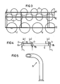
- FIG. 1 and 2 show a partial side view and an end view of a scaffold G which is set up directly on the corridor Fl and which is designed in the manner of a framework, the individual Supports, beams and cross struts are not specified.
- three conduit channels Lk1, Lk2 and Lk3 are located on the top of this frame G, which are formed by U-shaped profiles that are open at the top. From Fig. 1 it appears that below the line channel Lk3 directly in the corridor Fl barrels F are set up, from which lines labeled L are withdrawn upwards and introduced into the guide channel Fk3 via guide tubes Fr fastened to the frame G by means of tube holders Rh.
- Barrels F are transport containers with which single-stranded strands and cables are delivered.
- each barrel F there is a swirl-free line L in the form of a loose winding, which is arranged between the barrel wall and a concentrically inserted hollow cylinder.
- Each line L can then be withdrawn in a simple manner in the axial direction upward from the corresponding barrel F.
- lines L in particular single-core strands and cables, can also be supplied in the form of coils.
- the lines L can then also be pulled upward in the axial direction from such vertically installed coils and introduced into the corresponding line channels via associated guide tubes Fr.
- FIG. 3 shows that in addition to the drums F already shown in FIG. 1, coils S are also arranged below the frame G.
- the coils S are arranged in two rows labeled R1 and R2 offset from one another and set up directly in the hallway Fl (see FIGS. 1 and 2).
- the row in which the individual barrels F are set up next to one another is denoted by R3.
- Fig. 4 shows on a somewhat larger scale the mouth of the individual guide tubes Fr fastened by means of tube holders Rh into the conduit channels Lk1, Lk2 and Lk3 arranged on the top of the frame G, while Fig. 5 shows the details of a guide tube on an even larger scale Fr shows.
- a guide tube Fr has a vertical leg, the lower end of which is widened in a funnel shape in order to favor the threading and the entry of a line L.
- a pipe bend and a horizontal leg then adjoin the upper end of the vertical leg, the end face of the horizontal leg being inclined at an angle of 45 ° to the tube axis.
- This bevel at the end is matched to the fact that the horizontal legs of the guide tubes Fr also open at an angle of 45 ° backwards into the line channels Lk1, Lk2 or Lk3 and thus enable a particularly low-friction inlet of the individual lines L.
- the arrangement of the line channels Lk1, Lk2 and Lk3 on the top of the frame G shown in FIG. 4 is matched to the row arrangement of the coils S and the drums F shown in FIG. 3.
- the lines L drawn off from the coils S of the row R1 are introduced into the line channel Lk1
- the lines L drawn off from the coils S of the row R2 are introduced into the line channel Lk2.
- the lines L which are withdrawn from the drums F arranged in the row R3 are introduced into the line channel Lk3 in accordance with the illustration already shown in FIG. 1.
- both the barrels F and the coils S are immediately in the hallway Fl (see FIGS. 1 and 2). This is particularly favorable in the case of drums F, since these have to be transported with a forklift.
- the lighter spools S can also be moved manually.
- a kind of shelf can then be drawn into the framework G below the line channels Lk1 and Lk2, on which the coils S of the rows R1 and R2 are then placed.
- Such an arrangement has the advantage that a spare coil can then already be set up under each coil S and an exchange can be carried out particularly quickly.
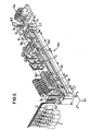
- FIG. 6 shows the corresponding assignment of a feed device, shown here only partially and purely schematically, to the line prefabrication device designated by Lve.
- Lve line prefabrication device
- the individual lines L which differ in line cross-section, in color and in insulation, are fanned out somewhat after leaving the respective cable ducts and threaded into associated guide bores in a sequencer denoted by Sq.
- This sequencer Sq is therefore a magazine in which all 35 line starts of lines L are stored.
- the sequencer Sq with the guide bores of the individual lines L arranged in a vertical row can then be moved programmably in the direction of the vertical double arrow Dpf in such a way that the desired line type falls into the engagement area of a line Fig. 6 comes not recognizable roll feed.
- the line ends are transferred to assigned collets of a workpiece carrier that is programmable in the x direction and the y direction. 6 shows several of these workpiece carriers Wt.
- the loops marked Sc are fixed on the assigned workpiece carriers Wt in such a way that the two line ends protrude rearward in the y direction, while the remaining area depends on the length downward in the z direction.
- the two line ends of a loop Sc are with the assigned workpiece carrier Wt in the x direction, one after the other, a stripping device Ae, nine different first stop tools Aw1, six different second stop tools Aw2, three different tools We for pushing on insulating sleeves and one Tinning station Vz fed, a shift in the y direction is also possible in each case.
- the stripping device Ae the insulations of the two cable ends are cut and torn off, the stripping length possibly being influenced by moving the workpiece carrier Wt in the y direction.
- different contact elements are fed in punched strips lengthways, ie in the y direction and, if strips are selected, are separated and attached to the cable end.
- the cable ends can also be tinned in the tinning station Vz. Since a yes-no statement is possible in each of the above-described operations, the processing of the beginning and end of a line L can also take place in completely different ways. For example, two different plug contacts can be attached. However, only one plug contact can be struck while the other end of the line is tinned in the tinning station Vz.
- the collets of the workpiece carrier Wt in question are opened and the entire loop Sc is removed with the aid of a gripper which cannot be seen in more detail in FIG. 6.
- the workpiece carrier is then transported downwards in a lift Lt1, returned in the x-direction and brought back up to the starting position via a lift Lt2, so that it can again take over a loop Sc there.
- the line ends of a loop Sc which are gripped by the gripper mentioned above are glued between an adhesive tape Kb and a paper tape Pb, whereupon the gripper opens and is moved back from the relevant workpiece carrier Wt to take over the next loop Sc.
- the adhesive tape Kb is pulled off an upper supply spool Vs1, while the paper tape Pb is pulled off a lower supply spool Vs2.
- the paper strip printed in this way is then glued in the correct position to the line ends between the adhesive tape Kb and the paper tape Pb.
- the lines L or loops Sc marked in this way and sequenced between adhesive tape Kb and paper tape Pb are then a kind of belts which are stored in a meandering shape in a stand magazine Sm.
- the stored belts with the lines L are then removed from the stator magazine Sm with the aid of a transport carriage and transported to the appropriate wiring locations. Since the order of the lines L in the belt and in the wiring list is the same, the wiring is particularly simple. In addition, confusion between different lines L can be practically excluded.
Landscapes
- Engineering & Computer Science (AREA)
- Manufacturing & Machinery (AREA)
- Guides For Winding Or Rewinding, Or Guides For Filamentary Materials (AREA)
Applications Claiming Priority (2)
| Application Number | Priority Date | Filing Date | Title |
|---|---|---|---|
| DE3620592 | 1986-06-19 | ||
| DE3620592 | 1986-06-19 |
Publications (2)
| Publication Number | Publication Date |
|---|---|
| EP0258544A2 true EP0258544A2 (fr) | 1988-03-09 |
| EP0258544A3 EP0258544A3 (fr) | 1989-05-17 |
Family
ID=6303286
Family Applications (1)
| Application Number | Title | Priority Date | Filing Date |
|---|---|---|---|
| EP87108114A Withdrawn EP0258544A3 (fr) | 1986-06-19 | 1987-06-04 | Installation d'alimentation pour l'alimentation en fils électriques d'un dispositif de travail |
Country Status (1)
| Country | Link |
|---|---|
| EP (1) | EP0258544A3 (fr) |
Family Cites Families (3)
| Publication number | Priority date | Publication date | Assignee | Title |
|---|---|---|---|---|
| US3686752A (en) * | 1971-02-26 | 1972-08-29 | Amp Inc | Method of making electrical leads |
| US4043494A (en) * | 1976-02-23 | 1977-08-23 | Amp Incorporated | Apparatus for feeding a plurality of wires |
| JPS6039787A (ja) * | 1983-08-12 | 1985-03-01 | 住友電気工業株式会社 | 端子圧着電線の自動成形装置 |
-
1987
- 1987-06-04 EP EP87108114A patent/EP0258544A3/fr not_active Withdrawn
Also Published As
| Publication number | Publication date |
|---|---|
| EP0258544A3 (fr) | 1989-05-17 |
Similar Documents
| Publication | Publication Date | Title |
|---|---|---|
| DE3838706C2 (de) | Verfahren zum Herstellen eines Kabelbaumes und Vorrichtung zur Durchführung dieses Verfahrens | |
| DE2649920C2 (de) | Kontaktieranlage für isolierte elektrische Leitungsdrähte | |
| DE102018131444B4 (de) | Ablängautomat und modulares Kabelverarbeitungscenter | |
| EP0134965B1 (fr) | Procédé et appareil pour appliquer des dispositifs de connexions sur conducteurs électriques | |
| DE212019000144U1 (de) | Modulares Kabelverarbeitungscenter | |
| EP0705491B1 (fr) | Cable faconne, notamment pour la construction d'armoires de distribution et de commande, son procede de fabrication et dispositif de fabrication dudit cable | |
| DE2808518C2 (de) | Maschine zum Anbringen von Kontaktelementen an elektrischen Drahtleitern | |
| DE68911289T2 (de) | Verfahren und vorrichtung zur bearbeitung von elektrischen kabelbäumen. | |
| DE3112205C2 (de) | Verfahren und Vorrichtung zur Positionierung von Schaltkabeladern | |
| EP1251605A1 (fr) | Appareil et méthode pour l'insertion de bout de câble dans des boítiers de connecteurs | |
| DE3620554A1 (de) | Verfahren und einrichtung zur vorfertigung elektrischer leitungen | |
| EP0258544A2 (fr) | Installation d'alimentation pour l'alimentation en fils électriques d'un dispositif de travail | |
| DE69600682T2 (de) | Vorrichtung zum automatischen aufwickeln von kabeln, drähten, seilen und ähnlichem | |
| DE69300735T2 (de) | Automatische Vorrichtung zum Anpressen von Kabelendklemmen. | |
| DE8616447U1 (de) | Zubringeeinrichtung für die Zufuhr elektrischer Leitungen zu einer Bearbeitungseinrichtung | |
| EP0250918A2 (fr) | Procédé et dispositif pour la préfabrication de câbles électriques | |
| DE4325355C1 (de) | Rangiervorrichtung und Verfahren zum Verlegen von Rangierleitungen innerhalb eines Verteilers | |
| WO2016189167A1 (fr) | Agencement de plusieurs lignes électriques | |
| DE102023005297B3 (de) | Verfahren und Vorrichtung zum Durchführen von Leitungen durch ein rohrförmiges Bauteil | |
| DE3789463T2 (de) | Verfahren zum Anschluss identifizierter Leiter an einen Verbinder und Anwendungsvorrichtung dafür. | |
| DE3011695C2 (de) | Verfahren und Vorrichtung zur aufeinanderfolgenden Zuführung der freien Enden von Einzeladern einer Flachbandleitung in eine Bearbeitungsmaschine | |
| EP0752742B1 (fr) | Méthode et dispositif de fabrication automatique de jeux de câbles | |
| DE102023115809A1 (de) | Vorrichtung und Verfahren zum Verlegen von Leitungen zur Ausbildung eines Leitungssatzes | |
| DE3820764C2 (fr) | ||
| DE3227266A1 (de) | Vorrichtung zur herstellung elektrischer kabelbaeume |
Legal Events
| Date | Code | Title | Description |
|---|---|---|---|
| PUAI | Public reference made under article 153(3) epc to a published international application that has entered the european phase |
Free format text: ORIGINAL CODE: 0009012 |
|
| AK | Designated contracting states |
Kind code of ref document: A2 Designated state(s): AT BE CH DE FR GB IT LI NL |
|
| PUAL | Search report despatched |
Free format text: ORIGINAL CODE: 0009013 |
|
| AK | Designated contracting states |
Kind code of ref document: A3 Designated state(s): AT BE CH DE FR GB IT LI NL |
|
| 17P | Request for examination filed |
Effective date: 19890925 |
|
| 17Q | First examination report despatched |
Effective date: 19911220 |
|
| STAA | Information on the status of an ep patent application or granted ep patent |
Free format text: STATUS: THE APPLICATION HAS BEEN WITHDRAWN |
|
| 18W | Application withdrawn |
Withdrawal date: 19940308 |
|
| RIN1 | Information on inventor provided before grant (corrected) |
Inventor name: GUENTHER, SIEGFRIED |