EP0258694A2 - Méthode pour déterminer le profil de distribution de chaque cylindre d'un moteur à combustion interne - Google Patents
Méthode pour déterminer le profil de distribution de chaque cylindre d'un moteur à combustion interne Download PDFInfo
- Publication number
- EP0258694A2 EP0258694A2 EP87111644A EP87111644A EP0258694A2 EP 0258694 A2 EP0258694 A2 EP 0258694A2 EP 87111644 A EP87111644 A EP 87111644A EP 87111644 A EP87111644 A EP 87111644A EP 0258694 A2 EP0258694 A2 EP 0258694A2
- Authority
- EP
- European Patent Office
- Prior art keywords
- engine
- cylinder
- time intervals
- internal combustion
- deceleration
- Prior art date
- Legal status (The legal status is an assumption and is not a legal conclusion. Google has not performed a legal analysis and makes no representation as to the accuracy of the status listed.)
- Withdrawn
Links
Images

Classifications
-
- F—MECHANICAL ENGINEERING; LIGHTING; HEATING; WEAPONS; BLASTING
- F02—COMBUSTION ENGINES; HOT-GAS OR COMBUSTION-PRODUCT ENGINE PLANTS
- F02P—IGNITION, OTHER THAN COMPRESSION IGNITION, FOR INTERNAL-COMBUSTION ENGINES; TESTING OF IGNITION TIMING IN COMPRESSION-IGNITION ENGINES
- F02P17/00—Testing of ignition installations, e.g. in combination with adjusting; Testing of ignition timing in compression-ignition engines
- F02P17/02—Checking or adjusting ignition timing
-
- F—MECHANICAL ENGINEERING; LIGHTING; HEATING; WEAPONS; BLASTING
- F02—COMBUSTION ENGINES; HOT-GAS OR COMBUSTION-PRODUCT ENGINE PLANTS
- F02D—CONTROLLING COMBUSTION ENGINES
- F02D41/00—Electrical control of supply of combustible mixture or its constituents
- F02D41/02—Circuit arrangements for generating control signals
- F02D41/14—Introducing closed-loop corrections
- F02D41/1497—With detection of the mechanical response of the engine
Definitions
- This invention is related to application Serial No. 871,930, filed June 9, 1986, entitled METHOD OF PERFORMING A POWER BALANCE ON AN INTERNAL COMBUSTION ENGINE, in the name of Keith A. Kreft and assigned to Sun Electric Corporation.
- This invention relates generally to internal combustion engine testing and, specifically, to a quick test method for determining the rotational angles 0 between successive firing events in an internal combustion engine.
- a fuel/air mixture is introduced into each cylinder where it is ignited to develop power.
- the ignition or combustion may be by way of an electrical spark produced by a spark device in communication with the cylinder and fuel/air mixture or by injection of fuel into a cylinder that is charged with air under pressure.
- each cylinder is subjected to a firing event once for every two revolutions of the engine.
- a distributor comprises a mechanically rotating shaft carrying a cam for operating a set of breaker points and a rotor contact for distributing high voltage energy from an ignition coil to the various spark plugs, in sequence.
- the firing events are initiated by each opening of the cam operated low voltage breaker points which causes a collapse of the magnetic field developed by in the ignition coil. This in turn induces a high voltage in the secondary winding of the ignition coil.
- the rotational angles (Q) between successive firing events are equal as are the angles between the successive occurrences of each cylinder reaching its point of maximum compression, commonly referred to as “top dead center” (TDC).
- Engine “timing” is generally referred to as the angle through which the engine rotates between the firing event of cylinder #1 and the top dead center of cylinder #1. The measurement of this angle is in engine degrees and is generally denoted as so many degrees “before top dead center” (BTDC) or “after top dead center” (ATDC) indicating whether the firing event occurs before or after the cylinder #1 TDC.
- each cylinder firing event will have the same "timing" relationship with its respective TDC point.
- a worn or bent distributor shaft or a worn bushing, for example, would result in the rotational angles 0 between successive firing events being unequal. This, in turn, could result in each . cylinder firing with a different amount of "timing," which is not desirable.
- the ability to determine the ⁇ 's of an engine with reasonable accuracy is a valuable tool in internal combustion engine diagnosis.
- the series of angles 9 for the cylinders of an internal combustion engine is herein referred to as the "0 profile" of the engine.
- angles ⁇ are important use in conducting a power balance test of the engine, which can yield valuable information about its operating condition.
- a power balance test notes the relative power contribution of each cylinder in the engine.
- the copending application describes a technique of determining the relative power contribution of each cylinder by comparing the relative increases in engine velocity of the engine under load for each cylinder from the time intervals between successive firing events of each cylinder. As the application describes, to calculate a correct relative velocity or acceleration rate for each cylinder, a fairly accurate measurement of the rotational angles between the firing events is required.
- the 0 for each cylinder is determined by measuring the time intervals between successive firing events in an engine running at an idle speed. This technique assumes that under idle speed conditions, each cylinder is contributing a similar amount of power and that, therefore, the time interval between successive firing events is a good measure of the actual rotational travel of the engine between the firing events. Since the angular rotation of the engine over a complete sequence of firing events is known (720 degress for a 4-cycle engine), the 0's may be quantitatively determined by proportioning the time intervals over 720 degrees. In practice, however, variation in the power contribution of each cylinder will affect the measured time intervals and, therefore, the idle running speed condition does not yield a sufficiently accurate measure of the ⁇ 's of the cylinders and a more accurate measurement technique is desirable.
- the invention is thus directed toward achieving a simple, accurate method of measuring the ⁇ profile of an engine, with signals currently gathered and processed on most types of automotive tune-up equipment.
- a principal object of the invention is to provide a novel method of measuring the ⁇ profile of an internal combustion engine.
- Another object of the invention is to provide a novel method of accurately determining the 0 profile of an internal combustion engine, utilizing signals that are currently gathered and processed by most automotive "tune-up" equipment.
- the ⁇ profile clearly can greatly influence the time intervals between successive cylinder firing events. While many engine teats are performed baaed upon an assumption that the ⁇ 's for the cylinder are equal, the ability to determine the ⁇ for each cylinder enables one to obtain much more accurate test results.
- the ⁇ for each cylinder is calculated from data taken or captured during an engine deceleration condition and then used to more accurately determine the relative velocity, relative acceleration and relative power contribution attributable to each cylinder during an engine acceleration condition. It will be appreciated that "cylinder” is used broadly to denote the power producing unit of an internal combustion engine including the cylinder, piston, connecting rod, spark plug, fuel injector, and the like.
- the method of the present invention is also applicable to non-spark ignited internal combustion engines, such as diesel engines.
- a cylinder firing event may be detected by means of some type of transducer associated with each cylinder.
- pickup means are required for sensing the cylinder firing events, The pickup means may either sense the actual cylinder firing, or sense a signal that is used to generate the actual firing or sense a signal that is result of a cylinder firing, and generate therefrom a pulse train to mark the cylinder firing events.
- a pickup for identifying or labelling a reference cylinder and its associated time interval is provided to synchronize the firing event data received. Such means are well known in the art.
- engine 10 is depicted as a block with cylinders 12, 14, 16 and 18 schematically indicated in dashed lines therein.
- a plurality of spark plugs 20, 22, 24 and 26 are mounted to engine 10 and connected over a cluster 27 of suitable spark plug wires to an ignition source 36.
- elements 20, 22, 24 and 26 may comprise diesel fuel injectors rather than spark plugs. Such would be the case for a diesel engine with cluster 27 comprising fuel lines rather than spark plug wires.
- ignition source 36 is also labelled as a fuel distributor in the event a diesel engine is being tested. It will also be appreciated that a spark ignited, fuel injected system is also contemplated, although not shown or described.
- Engine 10 may be equipped with conventional accessory apparatus such as a fan 28 and flywheel 30, none of which is relevant to the invention.
- a pair of sensors 32 and 34 are shown adjacent cluster 27, with sensor 32 being capable of picking up signal information from all cylinder firing events for cluster 27 and sensor 34 for picking up signal information from a single cylinder firing event corresponding to a reference cylinder in engine 10.
- sensors 32 and 34 are generally electrically sensitive, whereas for a diesel engine, they are typically pressure (or fluid flow) sensitive. It will be appreciated that techniques other than those illuatrated or described may be used to convey the aignala that are indicative of a firing event.
- microprocessor control 42 may be a simple microcomputer for taking the signal information from aignal conditioners 38 and 40 and processing it, in accordance with the inventive method, to produce a suitable output for an output device 44.
- This output may take the form of one or more of: a visual display; a printed report; or an audible message, . and could consist of a ⁇ profile or any manipulated form of the information presented as, for example, a timing deviation or timing variation.
- the 0's determined may be used to calculate the relative velocities, relative accelerations and the relative power contributions of each of the cylinders as specified in the referenced application.
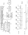
- FIG. 2 is a simplified showing of the relationship between cylinder firings and the engine-derived processing signals.
- the upper curve is a typical cylinder clock signal generated by signal conditioner 38. This is synchronized with the engine sync signal shown below when the designated cylinder (usually #1) fires (or in a diesel engine, receives injected fuel).
- the engine sync signal is generated by signal conditioner 40. Cylinder #1 is labelled 1 for convenience with the successively firing cylinders being labelled 2, 3 and 4, irrespective of their physically assigned numbers in the engine.
- the corresponding ⁇ 's are 91, ⁇ 2, ⁇ 3 and ⁇ 4,
- the curves depleted represent a conventional four cyole, four cylinder, non "wasted spark” engine where ⁇ 1+ ⁇ 2+ ⁇ 3+ ⁇ 4 ia equal to 720 degrees since each cylinder is fired once for every two engine revolutions.
- the reference designations T1, T2...Tn are serially assigned to the collected time intervals as the engine "rotates" so that successive firing intervals of cylinder #1 are T 1 , T5, T9, etc.
- the cylinder clock signal is supplied from signal conditioner 38 to microprocessor control 42 and the engine sync signal is supplied from signal conditioner 40 to microprocessor control 42.
- the flow chart of FIG. 3 generally explains the operation of the microprocessor in the inventive method.
- the engine is accelerated to a high speed condition and then allowed to decelerate at a rapid rate by limiting or shutting off the fuel supply or the ignition pulses, etc.
- a set of cylinder firing event time interval measurements is taken during the deceleration of the engine, labels are assigned and the measured time intervals stored. These time intervals are referred to as TL(1,2...n). From this set of data, the series of TL's of a maximum negative slope are selected. It is assumed that a fairly constant deceleration of the engine occurred during this period and ⁇ is calculated for each cylinder. The calculated ⁇ 's are quite accurate since under a rapid deceleration condition from a high speed, where the internal loading forces of the engine are high, power contribution of each cylinder is at its minimum, and therefore the effects of any small power contribution will be negligible.
- the appendix includes a method of calculating the ⁇ 's for an engine and a computer measurement and computation.
Landscapes
- Engineering & Computer Science (AREA)
- Chemical & Material Sciences (AREA)
- Combustion & Propulsion (AREA)
- Mechanical Engineering (AREA)
- General Engineering & Computer Science (AREA)
- Testing Of Engines (AREA)
- Combined Controls Of Internal Combustion Engines (AREA)
- Ignition Installations For Internal Combustion Engines (AREA)
Applications Claiming Priority (2)
| Application Number | Priority Date | Filing Date | Title |
|---|---|---|---|
| US89513686A | 1986-08-11 | 1986-08-11 | |
| US895136 | 1986-08-11 |
Publications (2)
| Publication Number | Publication Date |
|---|---|
| EP0258694A2 true EP0258694A2 (fr) | 1988-03-09 |
| EP0258694A3 EP0258694A3 (fr) | 1988-05-04 |
Family
ID=25404051
Family Applications (1)
| Application Number | Title | Priority Date | Filing Date |
|---|---|---|---|
| EP87111644A Withdrawn EP0258694A3 (fr) | 1986-08-11 | 1987-08-11 | Méthode pour déterminer le profil de distribution de chaque cylindre d'un moteur à combustion interne |
Country Status (1)
| Country | Link |
|---|---|
| EP (1) | EP0258694A3 (fr) |
Family Cites Families (4)
| Publication number | Priority date | Publication date | Assignee | Title |
|---|---|---|---|---|
| US4295363A (en) * | 1977-03-25 | 1981-10-20 | Harris Corporation | Apparatus for diagnosing faults in individual cylinders in an internal combustion engine |
| JPS55468A (en) * | 1978-03-17 | 1980-01-05 | Curry Roger G | Method and device for testing motor |
| US4292670A (en) * | 1979-06-11 | 1981-09-29 | Cummins Engine Company, Inc. | Diagnosis of engine power and compression balance |
| US4356725A (en) * | 1980-10-20 | 1982-11-02 | Rca Corporation | Testing the power of a turbocharged internal combustion engine |
-
1987
- 1987-08-11 EP EP87111644A patent/EP0258694A3/fr not_active Withdrawn
Also Published As
| Publication number | Publication date |
|---|---|
| EP0258694A3 (fr) | 1988-05-04 |
Similar Documents
| Publication | Publication Date | Title |
|---|---|---|
| US5041980A (en) | Method and apparatus for producing fault signals responsive to malfunctions in individual engine cylinders | |
| US5117681A (en) | Correction of systematic position-sensing errors in internal combustion engines | |
| US5915272A (en) | Method of detecting low compression pressure responsive to crankshaft acceleration measurement and apparatus therefor | |
| US3972230A (en) | Detecting malfunction in cylinders of internal combustion engines | |
| US5056360A (en) | Selection of velocity interval for power stroke acceleration measurements | |
| US4125894A (en) | Engine test and display apparatus | |
| JP2666232B2 (ja) | 内燃エンジンの燃焼状態検出装置 | |
| CA1050111A (fr) | Systeme de mesure du regime du moteur et des intervalles de l'allumage | |
| JP3466207B2 (ja) | 動作行程識別方法および識別装置 | |
| US4055993A (en) | Sub-cyclic measurement of speed of an internal combustion engine | |
| CA1252540A (fr) | Methode de reperage du point mort haut dans un moteur | |
| JPH05163997A (ja) | 内燃機関制御装置及び方法 | |
| CA1222316A (fr) | Temoin d'incoherence du fonctionnement d'un moteur a combustion interne | |
| US5189907A (en) | Internal combustion engine mapping apparatus and method | |
| US5562082A (en) | Engine cycle identification from engine speed | |
| EP0258694A2 (fr) | Méthode pour déterminer le profil de distribution de chaque cylindre d'un moteur à combustion interne | |
| JPS62118031A (ja) | 内燃機関の失火検出装置 | |
| JPH02112646A (ja) | 多気筒内熱機関用失火検出装置 | |
| US3677075A (en) | Method for the detection and classification of defects in internal combustion engines | |
| JP2757548B2 (ja) | 内燃機関の失火検出装置 | |
| JP2675921B2 (ja) | 内燃機関の失火検出装置 | |
| JP2527798B2 (ja) | 内燃機関の燃焼状態検出装置 | |
| JP3063007B2 (ja) | 内燃機関の失火診断装置 | |
| JPS5825583A (ja) | 不具合気筒検出装置 | |
| JPH0894462A (ja) | 内燃機関のトルク変動測定装置 |
Legal Events
| Date | Code | Title | Description |
|---|---|---|---|
| PUAI | Public reference made under article 153(3) epc to a published international application that has entered the european phase |
Free format text: ORIGINAL CODE: 0009012 |
|
| AK | Designated contracting states |
Kind code of ref document: A2 Designated state(s): DE FR GB IT NL |
|
| PUAL | Search report despatched |
Free format text: ORIGINAL CODE: 0009013 |
|
| AK | Designated contracting states |
Kind code of ref document: A3 Designated state(s): DE FR GB IT NL |
|
| RHK1 | Main classification (correction) |
Ipc: G01M 15/00 |
|
| STAA | Information on the status of an ep patent application or granted ep patent |
Free format text: STATUS: THE APPLICATION IS DEEMED TO BE WITHDRAWN |
|
| 18D | Application deemed to be withdrawn |
Effective date: 19881105 |
|
| RIN1 | Information on inventor provided before grant (corrected) |
Inventor name: KREFT, KEITH A. |