EP0259772A2 - Dispositif et procédé de fabrication d'un alliage à base de cuivre - Google Patents
Dispositif et procédé de fabrication d'un alliage à base de cuivre Download PDFInfo
- Publication number
- EP0259772A2 EP0259772A2 EP87112809A EP87112809A EP0259772A2 EP 0259772 A2 EP0259772 A2 EP 0259772A2 EP 87112809 A EP87112809 A EP 87112809A EP 87112809 A EP87112809 A EP 87112809A EP 0259772 A2 EP0259772 A2 EP 0259772A2
- Authority
- EP
- European Patent Office
- Prior art keywords
- spout
- alloying
- copper
- molten copper
- passageway
- Prior art date
- Legal status (The legal status is an assumption and is not a legal conclusion. Google has not performed a legal analysis and makes no representation as to the accuracy of the status listed.)
- Granted
Links
Images

Classifications
-
- C—CHEMISTRY; METALLURGY
- C22—METALLURGY; FERROUS OR NON-FERROUS ALLOYS; TREATMENT OF ALLOYS OR NON-FERROUS METALS
- C22B—PRODUCTION AND REFINING OF METALS; PRETREATMENT OF RAW MATERIALS
- C22B9/00—General processes of refining or remelting of metals; Apparatus for electroslag or arc remelting of metals
-
- B—PERFORMING OPERATIONS; TRANSPORTING
- B22—CASTING; POWDER METALLURGY
- B22D—CASTING OF METALS; CASTING OF OTHER SUBSTANCES BY THE SAME PROCESSES OR DEVICES
- B22D11/00—Continuous casting of metals, i.e. casting in indefinite lengths
- B22D11/10—Supplying or treating molten metal
- B22D11/11—Treating the molten metal
Definitions
- the present invention relates to an apparatus and a method for manufacturing a copper-base alloy having a quite uniform chemical composition.
- the batch process has been disadvantageous in that every time the kinds of copper-base alloys to be manufactured are changed, the inside of the melting furnace has to be washed. As a result, a large quantity of a melt has been required for washing, and it is laborious to carry out such washing. In addition, inasmuch as the intermittent operation deteriorates the rate of operation of the melting furnace, the productivity has been lowered, resulting in a high production cost. Besides, since the solute constituents are difficult to be mixed uniformly with copper, the alloy thus produced has not complied with a desired quality.
- Another object is to provide a method of manufacturing a copper alloy by using such an apparatus.
- an apparatus for manufacturing a copper-base alloy comprising an alloying spout inclined downwardly from one end toward the other end for flowing a molten copper therethrough, the alloying spout including an inlet at the one end and an outlet at the other end and having an elongated passageway through which the inlet communicates with the outlet, whereby the molten copper introduced from the inlet can flow downwardly through the passageway to the outlet; feed means connected to the alloying spout for introducing at least one solid solute constituent into the passageway of the alloying spout to thereby mix the solute constituent with the molten copper to produce the molten copper-base alloy; and a tundish disposed at the other end of the alloying spout for receiving the molten copper-base alloy tapped from the alloying spout.
- a method of manufacturing a copper-base alloy comprising the steps of providing an apparatus comprising an alloying spout inclined downwardly from one end toward the other end for flowing a molten copper therethrough, the alloying spout including an inlet at the one end and an outlet at the other end and having an elongated passageway through which the inlet communicates with the outlet, and feed means connected to the alloying spout for introducing at least one solid solute constituent into the passageway of the alloying spout; continuously introducing the molten copper from the inlet into the passageway of the alloying spout and causing the molten copper to flow downwardly through the passageway to the outlet; and continuously introducing the at least one solid solute constituent into the passageway of the alloying spout through the feed means to mix the solute constituent with the molten copper to produce the copper-base alloy.
- FIGs. 1 and 2 there is illustrated an apparatus for manufacturing a copper-base alloy, which comprises a melting crucible furnace 10 for melting a solid copper material to produce a molten copper.
- a pouring spout 12 which is inclined downwardly from one end toward the other end and has an inlet 12a at the one end and an outlet 12b at the other end, is connected at the one end to the melting furnace 10, and a holding furnace 14 is disposed at the other end of the pouring spout 12 for holding the molten copper tapped from the pouring spout 12 in an oxygen-free state and keeping the temperature of the molten copper at a prescribed level.
- the pouring spout 12 is accommodated in a refractory brick-lined housing 13, and a reducing gas, which consists of a mixture of carbon monoxide gas and nitrogen gas, is contained in the spout 12.
- An alloying spout 16 which is inclined downwardly from one end toward the other end, is connected at the one end to the holding furnace 14 for causing the molten copper tapped from the holding furnace 14 to flow downwardly therethrough.
- the alloying spout 16 is comprised of a hermetically sealable casing having an inlet 16a at the one end and an outlet 16b at the other end and an elongated passageway 16c through which the inlet 16a communicates with the outlet 16b, and an inert gas or a reducing gas is filled in the passageway 16c.
- the alloying spout 16 is accommodated in a refractory brick-lined housing 13.
- First and second feeders 20 and 22 are respectively connected to the alloying spout 16 for introducing solid solute constituents into the passageway 16c of the alloying spout 16, the first feeder 20 being connected to an upstream portion of the spout 16 adjacent to the one end thereof while the second feeder 22 is connected to a downstream portion of the spout 16 adjacent to the other end thereof.
- the passageway 16c of the alloying spout 16 should be long enough to melt the solute constituents to mix them with the molten copper during the passage of the molten copper through the passageway 16c.
- the solute constituents to be alloyed with copper are different depending upon the kinds of the copper alloys to be produced.
- solute constituents many elements such as chromium (Cr), zirconium (Zr), titanium (Ti), silicon (Si), nickel (Ni), iron (Fe), magnesium (Mg), tin (Sn), tellurium (Te), arsenic (As), phosphorus (P), aluminium (Al), zinc (Zn), beryllium (Be), W (tungsten) and the like may be alloyed with copper.
- a solid material of a high purity should preferably be used. Such pure solid material may be in the form of granules, grains, wires, pieces, powders or the like.
- the outer shell of the tundish 18 has an opening in the bottom, in which is fitted a nozzle 18a with a stopper 24. By raising and lowering the stopper 24, the quantity of the molten copper alloy to be tapped from the tundish 18 can be controlled.
- a mould 26 is disposed under the tundish 18 for continuously casting the molten alloy tapped from the nozzle 18a of the tundish 18 to produce a cast copper alloy.
- a sealing shell 28 is mounted between the tundish 18 and the mould 26 for hermetically sealing the inside of the mould and the tundish, and an inert gas is supplied thereinto.
- the melting furnace 10 is charged with the solid copper, and the copper is melted. Specifically, in this melting furnace 10, pieces of charcoal are added to prevent the molten copper from being exposed to the air, so that low oxygen molten copper, which contains an oxygen content of not greater than 50 ppm, is produced in it.
- the molten copper in the melting furnace 10 exceeds a prescribed level, it overflows into the pouring spout 12 and passes therethrough to the holding furnace 14.
- the low oxygen molten copper is reduced by the reducing gas contained therein to an oxygen free molten copper, an oxygen content of which is not greater than 10 ppm.
- the oxygen-free molten copper is tapped into the holding furnace 14 and kept at a prescribed temperature. Then, the molten copper overflows into the alloying spout 16 and passes through the passageway 16c thereof to flow into the tundish 18.
- first solid solute constituents which have high melting points compared with copper and are difficult to be melted, are added through the first feeder 20 into the passageway 16c of the alloying spout 16
- second solute constituents which have low melting points compared with copper
- the solute constituents introduced into the passageway 16c are mixed with the molten copper uniformly and melted quickly, and thus a molten copper-base alloy of a uniform chemical composition is produced.
- the first solute constituents have high melting points and are difficult to be melted, they are added in the alloying spout 16 at its upstream portion, and therefore they can be sufficiently alloyed with the copper during the passage through the elongated passageway 16c.
- the second solute constituents having low melting points they are added in the spout 16 at its downstream portion, but are easily mixed with and alloyed with the copper.
- Some solute constituents having higher solubilities may be added in the tundish 18. Further, the solute constituents may preferably be preheated to temperatures near to their melting points before they are added.
- the molten copper alloy thus produced is tapped from the alloying spout 16 into the tundish 18, and teemed from the tundish 18 into the mould 26 through the nozzle 18a, so that a cast product 30 of copper alloy is manufactured.
- the solute constituents are alloyed with the oxygen free copper in the alloying spout 16, they may be alloyed with low oxygen copper or deoxidized copper.
- the solute constituent to be added is an active or reactive element such as Cr, Ti, Zr, Si, Mg, Ca, Al and the like, which has a great affinity for oxygen, such element combines with oxygen to thereby lower the yield of the alloy.
- the low oxygen copper may be preferably used.
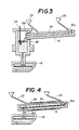
- Fig. 3 shows a modified apparatus in accordance with the present invention which differs from the apparatus of Figs. 1 and 2 only in that there is provided a heating furnace 32 between the alloying spout 16 and the tundish 18 for heating the molten alloy tapped from the spout 16.
- the heating furnace 32 is a high frequency induction furnace, to which is attached a bubbling apparatus 34 for blowing an inert gas such as argon into the molten alloy to stir it up.
- An alloy produced by the apparatus of this embodiment contains a high content of solute elements.
- Fig. 4 shows another modified apparatus in accordance with the present invention which differs from the apparatus of Figs. 1 and 2 only in that heating means 36 is attached to the alloying spout 16 for heating the molten copper and the solute elements passing through the passageway 16c.
- each of the spouts 12 and 16 may be a spout of a U-shaped cross section housed in a hermetically sealable refractory brick-lined housing.
- the solute constituents are continuously added in the molten copper which is flowing at a sufficient flow rate. Accordingly, the solute constituents added are stirred by the flow of the molten copper and mixed therewith uniformly and melted quickly, and thus the copper-base alloy of a uniform chemical composition is produced continuously.
- the quantity of the solute constituents to be added in the alloying spout is changed, and besides different kinds of alloys can easily be manufactured. Further, since the alloying is carried out in the alloying spout, there is no need to wash the inside of the melting furnace when changing the kinds of alloys to be manufactured, thus increasing the operating rate of the apparatus substantially.
- Cr-Cu alloys of a desired Cr content ranging from 0.25 to 0.40 % by weight were manufactured using the apparatus of Figs. 1 and 2.
- Cr-Cu alloys of the same desired Cr content were produced by the conventional batch process. The data on Cr contents and the like for such alloys are shown in TABLE 1.
- the alloys obtained by the apparatus in accordance with the present invention exhibits generally uniform Cr contents and complies with the desired specification.
- Cr contents of the alloys obtained by the conventional batch process vary widely, and besides there is an alloy which does not meet the specification.
- Zr-Cu alloys of a desired Zr content ranging from 0.07 to 0.13 % by weight were manufactured by using the apparatus of Figs. 1 and 2, and by the conventional batch process for comparison purposes.
- the data on Zr contents and the like for such alloys are shown in TABLE 2.
- the alloys obtained by the apparatus in accordance with the present invention exhibits a generally uniform Zr content and complies with the desired specification.
- Zr contents of the alloys obtained by the conventional batch process vary widely, and besides there is an alloy which does not meet requirements. Further, although Zr is reactive and is liable to oxidation, Zr contents of the alloys obtained by the apparatus of the invention are relatively higher as compared with the alloys obtained by the conventional process.
- Mg-Cu alloys of a desired Mg content ranging from 0.02 to 0.08 % by weight were manufactured by using the apparatus of Figs. 1 and 2, and by the conventional batch process for comparison purposes.
- the data on Mg contents and the like for such alloys are shown in TABLE 3.
- the alloys obtained by the apparatus in accordance with the present invention exhibits a generally uniform Mg content and complies with the desired specification.
- Mg contents of the alloys obtained by the conventional batch process vary widely, and besides there is an alloy which does not meet requirements.
- Mg contents of the alloys obtained by the apparatus of the invention are relatively higher as compared with the alloys obtained by the conventional process.
- Cr-Cu alloys of a desired Cr content ranging from 0.75 to 0.90 % by weight were manufactured using the apparatus of Fig. 3 which includes the heating furnace 32.
- Cr-Cu alloys of the same desired Cr content were produced by the conventional batch process. The data on Cr contents and the like for such alloys are shown in TABLE 4.
- the alloys produced by the apparatus in accordance with the present invention exhibits a generally uniform Cr content and complies with the desired specification.
- Cr contents of the alloys obtained by the conventional batch process vary widely, and besides there are alloys which do not meet requirements.
- Granules of a pure Cr metal each of which had a high melting point and had a purity of not less than 99.7 % by weight and a granular size of 0.1 mm to 1.5 mm, were alloyed with copper using the apparatus of Figs. 1 and 2, and a copper alloy which had a uniform chemical composition containing a Cr content of 1.1 % by weight was successfully obtained.
- smashed pieces of Ti each having a purity of not less than 99.6 % by weight and a size of 3.0 mm to 5.0 mm
- pieces of Zr each having a purity of not less than 98.0 % by weight and a size of 1.0 mm ⁇ 5.0 mm ⁇ 10.0 mm
- smashed pieces of Si each having a purity of not less than 99.9 % by weight and a size of 3.0 mm ⁇ 5.0 mm
- spherical pieces of Ni each having a purity of not less than 99.8 % by weight and a size of 8 mm
- pieces of Fe each having a purity of not less than 99.9 % by weight and a size of 1 mm ⁇ 2 mm to 5 mm
- copper alloys which contain Ti content of 2.5 % by weight, Zr content of 0.2 % by weight, Si content of 1.7 % by weight, Ni content of 2.5 % by weight, and Fe content of 2.3 % by weight, respectively
- a Cu-Cr-Ti-Si-Ni-Sn alloy was produced by the apparatus of Figs. 1 and 2. In this case, by adding the alloying elements in the order of Cu-Cr-Ti-Si-Ni-Sn, an alloy having Cr content of 0.3 % was obtained.
Landscapes
- Engineering & Computer Science (AREA)
- Mechanical Engineering (AREA)
- Chemical & Material Sciences (AREA)
- Manufacturing & Machinery (AREA)
- Materials Engineering (AREA)
- Metallurgy (AREA)
- Organic Chemistry (AREA)
- Manufacture And Refinement Of Metals (AREA)
- Continuous Casting (AREA)
Applications Claiming Priority (4)
| Application Number | Priority Date | Filing Date | Title |
|---|---|---|---|
| JP61206133A JPS6362829A (ja) | 1986-09-02 | 1986-09-02 | 合金溶体の製造装置 |
| JP206134/86 | 1986-09-02 | ||
| JP61206134A JPS6362830A (ja) | 1986-09-02 | 1986-09-02 | 合金溶体の製造装置 |
| JP206133/86 | 1986-09-02 |
Publications (3)
| Publication Number | Publication Date |
|---|---|
| EP0259772A2 true EP0259772A2 (fr) | 1988-03-16 |
| EP0259772A3 EP0259772A3 (en) | 1988-09-14 |
| EP0259772B1 EP0259772B1 (fr) | 1992-08-05 |
Family
ID=26515465
Family Applications (1)
| Application Number | Title | Priority Date | Filing Date |
|---|---|---|---|
| EP87112809A Expired - Lifetime EP0259772B1 (fr) | 1986-09-02 | 1987-09-02 | Dispositif et procédé de fabrication d'un alliage à base de cuivre |
Country Status (4)
| Country | Link |
|---|---|
| EP (1) | EP0259772B1 (fr) |
| KR (1) | KR940006287B1 (fr) |
| DE (1) | DE3780887T2 (fr) |
| FI (1) | FI88730C (fr) |
Cited By (5)
| Publication number | Priority date | Publication date | Assignee | Title |
|---|---|---|---|---|
| FR2679162A1 (fr) * | 1991-07-18 | 1993-01-22 | Siderurgie Fse Inst Rech | Dispositif de transfert par jet de metal liquide, notamment d'une poche de coulee continue vers un repartiteur. |
| EP1240958A3 (fr) * | 2001-03-14 | 2003-01-02 | KM Europa Metal Aktiengesellschaft | Dispositif pour couler un alliage fondu de cuivre |
| US8176966B2 (en) | 2007-11-30 | 2012-05-15 | The Furukawa Electric Co., Ltd. | Process and equipment for producing copper alloy material |
| CN104357698A (zh) * | 2014-09-28 | 2015-02-18 | 江苏中容铜业有限公司 | 一种引线框架铜带基材生产系统 |
| CN111618291A (zh) * | 2020-06-02 | 2020-09-04 | 中国重型机械研究院股份公司 | 一种炼钢连铸无氧管道输送装置及方法 |
Family Cites Families (5)
| Publication number | Priority date | Publication date | Assignee | Title |
|---|---|---|---|---|
| DE1433570A1 (de) * | 1964-05-20 | 1968-11-07 | Kaiser Ind Corp | Kontinuierliches Verfahren und Vorrichtung zur Erzeugung von Gusskoerpern aus oxydierbaren Metallen |
| GB1181518A (en) * | 1966-08-15 | 1970-02-18 | Ass Elect Ind | Improvements relating to Production of Cast Metal. |
| SE384805B (sv) * | 1971-06-03 | 1976-05-24 | I Properzi | Forfarande och anordning for avgasning och overforing av smelt metall |
| US3836360A (en) * | 1972-07-10 | 1974-09-17 | Anaconda Co | Method and apparatus for pre-heating and adding master alloy to a copper melt |
| US3785427A (en) * | 1972-08-15 | 1974-01-15 | Metallurg Hoboken Overpett | Casting of deoxidized copper |
-
1987
- 1987-09-01 FI FI873791A patent/FI88730C/fi not_active IP Right Cessation
- 1987-09-01 KR KR1019870009673A patent/KR940006287B1/ko not_active Expired - Fee Related
- 1987-09-02 EP EP87112809A patent/EP0259772B1/fr not_active Expired - Lifetime
- 1987-09-02 DE DE8787112809T patent/DE3780887T2/de not_active Expired - Fee Related
Cited By (7)
| Publication number | Priority date | Publication date | Assignee | Title |
|---|---|---|---|---|
| FR2679162A1 (fr) * | 1991-07-18 | 1993-01-22 | Siderurgie Fse Inst Rech | Dispositif de transfert par jet de metal liquide, notamment d'une poche de coulee continue vers un repartiteur. |
| EP1240958A3 (fr) * | 2001-03-14 | 2003-01-02 | KM Europa Metal Aktiengesellschaft | Dispositif pour couler un alliage fondu de cuivre |
| US6602461B2 (en) | 2001-03-14 | 2003-08-05 | Km Europa Metal Ag | Arrangement for pouring a pourable melt made up of a copper alloy |
| US8176966B2 (en) | 2007-11-30 | 2012-05-15 | The Furukawa Electric Co., Ltd. | Process and equipment for producing copper alloy material |
| CN104357698A (zh) * | 2014-09-28 | 2015-02-18 | 江苏中容铜业有限公司 | 一种引线框架铜带基材生产系统 |
| CN104357698B (zh) * | 2014-09-28 | 2016-06-22 | 江苏中容铜业有限公司 | 一种引线框架铜带基材生产系统 |
| CN111618291A (zh) * | 2020-06-02 | 2020-09-04 | 中国重型机械研究院股份公司 | 一种炼钢连铸无氧管道输送装置及方法 |
Also Published As
| Publication number | Publication date |
|---|---|
| FI88730B (fi) | 1993-03-15 |
| EP0259772A3 (en) | 1988-09-14 |
| KR940006287B1 (ko) | 1994-07-14 |
| FI88730C (fi) | 1993-06-28 |
| FI873791A7 (fi) | 1988-03-03 |
| EP0259772B1 (fr) | 1992-08-05 |
| KR880004113A (ko) | 1988-06-01 |
| DE3780887D1 (de) | 1992-09-10 |
| DE3780887T2 (de) | 1993-01-14 |
| FI873791A0 (fi) | 1987-09-01 |
Similar Documents
| Publication | Publication Date | Title |
|---|---|---|
| US4248630A (en) | Method of adding alloy additions in melting aluminum base alloys for ingot casting | |
| US4832911A (en) | Method of alloying aluminium | |
| EP0662522A2 (fr) | Procédé et appareil pour la fabrication de l'acier dans un panier | |
| US6039920A (en) | Process for making rhenium-containing alloys | |
| US5062614A (en) | Apparatus and method for manufacturing copper-base alloy | |
| CN100478469C (zh) | 铜-硼母合金及其在制备银-铜合金中的应用 | |
| US4981514A (en) | Method for manufacturing copper-base alloy | |
| EP0259772B1 (fr) | Dispositif et procédé de fabrication d'un alliage à base de cuivre | |
| US4652299A (en) | Process for treating metals and alloys for the purpose of refining them | |
| US4088475A (en) | Addition of reactive elements in powder wire form to copper base alloys | |
| GB2299099A (en) | Process for producing grain refining master alloys. | |
| EP0185540A2 (fr) | Procédé pour l'affinage du grain de silicium primaire dans les alliages hypereutectiques Al-Si | |
| CN1009256B (zh) | 铝锂合金熔铸设备及方法 | |
| KR940010770B1 (ko) | 구리합금의 제조방법 | |
| US4585474A (en) | Method of and prealloy for the production of titanium alloys | |
| EP0720967B1 (fr) | Silicium et ferrosilicium métallurgique à basse teneur en oxygène | |
| JP2503119B2 (ja) | ベリリウム銅合金の鋳造方法 | |
| US4582533A (en) | Method of and prealloy for the production of titanium alloys | |
| CN111518990B (zh) | 一种控制易切削钢中合金元素均匀分布的方法 | |
| JP2000317580A (ja) | 銅合金の鋳造方法 | |
| US4014688A (en) | Contact material for high-power vacuum circuit breakers | |
| US4251266A (en) | Method for taking care of metallic waste products by remelting | |
| US4588019A (en) | Methods of controlling solidification of metal baths | |
| US3948652A (en) | Contact material for high-power vacuum circuit breakers | |
| US3993481A (en) | Contact material for high-power vacuum circuit breakers |
Legal Events
| Date | Code | Title | Description |
|---|---|---|---|
| PUAI | Public reference made under article 153(3) epc to a published international application that has entered the european phase |
Free format text: ORIGINAL CODE: 0009012 |
|
| AK | Designated contracting states |
Kind code of ref document: A2 Designated state(s): DE FR GB SE |
|
| PUAL | Search report despatched |
Free format text: ORIGINAL CODE: 0009013 |
|
| AK | Designated contracting states |
Kind code of ref document: A3 Designated state(s): DE FR GB SE |
|
| 17P | Request for examination filed |
Effective date: 19881114 |
|
| 17Q | First examination report despatched |
Effective date: 19890630 |
|
| RAP1 | Party data changed (applicant data changed or rights of an application transferred) |
Owner name: MITSUBISHI MATERIALS CORPORATION |
|
| GRAA | (expected) grant |
Free format text: ORIGINAL CODE: 0009210 |
|
| AK | Designated contracting states |
Kind code of ref document: B1 Designated state(s): DE FR GB SE |
|
| ET | Fr: translation filed | ||
| REF | Corresponds to: |
Ref document number: 3780887 Country of ref document: DE Date of ref document: 19920910 |
|
| PLBE | No opposition filed within time limit |
Free format text: ORIGINAL CODE: 0009261 |
|
| STAA | Information on the status of an ep patent application or granted ep patent |
Free format text: STATUS: NO OPPOSITION FILED WITHIN TIME LIMIT |
|
| 26N | No opposition filed | ||
| EAL | Se: european patent in force in sweden |
Ref document number: 87112809.6 |
|
| PGFP | Annual fee paid to national office [announced via postgrant information from national office to epo] |
Ref country code: GB Payment date: 19980814 Year of fee payment: 12 |
|
| PGFP | Annual fee paid to national office [announced via postgrant information from national office to epo] |
Ref country code: FR Payment date: 19980821 Year of fee payment: 12 Ref country code: DE Payment date: 19980821 Year of fee payment: 12 |
|
| PGFP | Annual fee paid to national office [announced via postgrant information from national office to epo] |
Ref country code: SE Payment date: 19980824 Year of fee payment: 12 |
|
| PG25 | Lapsed in a contracting state [announced via postgrant information from national office to epo] |
Ref country code: GB Free format text: LAPSE BECAUSE OF NON-PAYMENT OF DUE FEES Effective date: 19990902 |
|
| PG25 | Lapsed in a contracting state [announced via postgrant information from national office to epo] |
Ref country code: SE Free format text: THE PATENT HAS BEEN ANNULLED BY A DECISION OF A NATIONAL AUTHORITY Effective date: 19990929 |
|
| GBPC | Gb: european patent ceased through non-payment of renewal fee |
Effective date: 19990902 |
|
| EUG | Se: european patent has lapsed |
Ref document number: 87112809.6 |
|
| PG25 | Lapsed in a contracting state [announced via postgrant information from national office to epo] |
Ref country code: FR Free format text: LAPSE BECAUSE OF NON-PAYMENT OF DUE FEES Effective date: 20000531 |
|
| PG25 | Lapsed in a contracting state [announced via postgrant information from national office to epo] |
Ref country code: DE Free format text: LAPSE BECAUSE OF NON-PAYMENT OF DUE FEES Effective date: 20000701 |
|
| REG | Reference to a national code |
Ref country code: FR Ref legal event code: ST |