EP0260112A2 - Demontierbare Kranstruktur - Google Patents
Demontierbare Kranstruktur Download PDFInfo
- Publication number
- EP0260112A2 EP0260112A2 EP87307934A EP87307934A EP0260112A2 EP 0260112 A2 EP0260112 A2 EP 0260112A2 EP 87307934 A EP87307934 A EP 87307934A EP 87307934 A EP87307934 A EP 87307934A EP 0260112 A2 EP0260112 A2 EP 0260112A2
- Authority
- EP
- European Patent Office
- Prior art keywords
- boom
- mast
- crane
- base
- lifting
- Prior art date
- Legal status (The legal status is an assumption and is not a legal conclusion. Google has not performed a legal analysis and makes no representation as to the accuracy of the status listed.)
- Withdrawn
Links
Images



Classifications
-
- B—PERFORMING OPERATIONS; TRANSPORTING
- B66—HOISTING; LIFTING; HAULING
- B66C—CRANES; LOAD-ENGAGING ELEMENTS OR DEVICES FOR CRANES, CAPSTANS, WINCHES, OR TACKLES
- B66C23/00—Cranes comprising essentially a beam, boom, or triangular structure acting as a cantilever and mounted for translatory of swinging movements in vertical or horizontal planes or a combination of such movements, e.g. jib-cranes, derricks, tower cranes
- B66C23/18—Cranes comprising essentially a beam, boom, or triangular structure acting as a cantilever and mounted for translatory of swinging movements in vertical or horizontal planes or a combination of such movements, e.g. jib-cranes, derricks, tower cranes specially adapted for use in particular purposes
- B66C23/36—Cranes comprising essentially a beam, boom, or triangular structure acting as a cantilever and mounted for translatory of swinging movements in vertical or horizontal planes or a combination of such movements, e.g. jib-cranes, derricks, tower cranes specially adapted for use in particular purposes mounted on road or rail vehicles; Manually-movable jib-cranes for use in workshops; Floating cranes
- B66C23/52—Floating cranes
Definitions
- This invention relates to a stowable crane design, particularly though not exclusively for marine use.
- One common configuration includes one or more frame sections called jackets which extend from the sea floor above the ocean surface. Deck sections are supported on the jacket above the ocean level to carry the necessary drilling or production equipment. Each of the components of the platform can be several hundred feet long and weigh thousands of tons.
- cranes have been employed.
- these cranes are mounted on a dedicated barge, i.e., a barge that is designed exclusively for carrying the crane.
- these cranes have a rotating base which permits the boom to extend out over the water for lifting and, after lifting is complete, rotate the boom back along the length of the barge for storage.
- Such cranes extend quite high and are extremely limited in their ability to pass underneath bridges and other obstructions. Therefore, they typically cannot be towed into harbours or navigatable rivers where such a floating crane could be usefully employed to lift other types of loads.
- These cranes also are very limited in their seagoing capacity.
- Such cranes present a large area for wind forces to act on and a high center of gravity which limits the ability to withstand wave motion.
- an improved crane includes a base and a mast. Structure is provided for pivotally mounting one end of the mast to the base for movement between a stowed position and a lifting position.
- a boom is mounted at one end to a boom seat assembly. The boom seat assembly is movable along the base between a stowed position and a lifting position.
- a backleg tension bearing member extends between the base and the mast.
- a second tension bearing element extends between the mast and the boom.
- Structure is provided for moving the boom seat assembly from the stowed position to the lifting position, the boom movement tensioning the second tension bearing member to pivot the mast to a lifting position.
- the backleg tension bearing member comprises at least one tension leg including a plurality of telescoping elements.
- the tension leg telescopes from a stowed position to a lifting position as the mast pivots from the stowed position to the lifting position.
- Structure is provided to limit the range of telescoping motion.
- the tension leg supports the mast in the stowed position.
- Crane 10 is designed for mounting on a barge 12 that is not specifically dedicated solely for use with the crane 10.
- the crane 10 can be removed relatively quickly, perhaps within one or two days, to permit the barge to be used to carry jackets, deck sections or any other appropriate load.
- the crane 10 can be lowered to a stowed configuration, as seen in FIGURE 5, to significantly reduce the height of the crane and barge assembly for passage under obstructions such as bridges across a channel along which the crane must travel.
- the stowed configuration greatly reduces the height of the center of gravity of the crane and permits the crane and barge to survive much worse weather conditions than is possible with equivalent capacity non-stowable cranes.
- the barge 12 can be seen to have an upper flat deck 14 with two parallel beams 16 running the length of the barge and spaced on opposite sides of the elongate line of symmetry of the barge.
- the crane 10 is provided with two parallel beams 18 spaced to slide on and rest atop beams 16. Structure (not shown) can be used to rigidly tie the beams 18 to the beam 16.
- the beams 18 form a skid base which permits the crane to be slid off the barge from either end to release the barge for other use.
- the crane 10 includes several main components, including base 20, which is formed, in part, by beams 18.
- a boom 22 is pivotally mounted to the base through a boom seat assembly 23 which comprises a pair of slidable boom seats 24 and 25, each slidable along the top of one of the beams 18.
- a mast 26 is pivotallty mounted to the base 20 which permits pivotal movement of the mast between the stowed position, seen in FIGURE 5 and the lifting position, shown in FIGURES 1 and 4.
- a backleg assembly 28 is pivotally mounted between the rear end of the base and the top of mast 26.
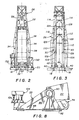
- Back leg assembly 28 includes a pair of telescoping backlegs 30 which can telescope between a stowed position, as seen in FIGURE 5, and an extended, lifting position, as seen in FIGURE 1.
- Backlegs 30 support the mast 26 when in the stowed position to eliminate the need for a separate mast rest. When backlegs 30 are in the extended, lifting position, they carry the tension forces necessary to support the mast, boom and load.
- the boom seat assembly 23 is locked in the lifting configuration at the forward end of the crane.
- the mast is pivoted to its lifting position and held in this position by the weight of the boom and load being lifted.
- the backleg assembly 28 has extended to its full length to support the boom, mast and load from the base.
- the boom 22 can be pivoted from the posiition shown in solid line, where the main lifting block 32 is spaced far from the barge perimeter, to the position shown in phantom line.
- the boom seat assembly 23 is released from the lifting configuration and slid along the length of the beams toward the rear of the base, as seen in FIGURE 4.
- the mast 26 is configured to permit a portion of the boom to move between the mast elements until the boom seat assembly is positioned proximate the rear of the base.
- the mast 26 then pivots to its stowed configuration, as seen in FIGURE 5, with the backleg assembly 28 telescoping to its minimum length and supporting the mast 26.
- a main lifting block rated capacity of 5090 tonnes (5,000 tons), with a 10% impact load factor is provided.
- the total height of the crane can be reduced from a minimum of about 61m (200 ft.) in the lifting configuration to about 27m (90ft.) in the stowed configuration.
- the length of the backleg assembly varies between about 82m (270 ft.) in the extended position and 30m (100 ft.) in the stowed configuration.
- the mast is positioned at an angle of about 70° relative to the horizontal and, in the stowed position, rests at an angle about 20° relative to the horizontal.
- the boom can vary from an angle of about 68° relative to the horizontal in the lifting configuration to an angle of about 8° to the horizontal in the stowed configuration.
- the length of the boom from its pivot axis at the boom seat assembly 23 to the main fall is about 82m (270 ft.).
- the horizontal distance between the pivot axis of the boom at the boom seat assembly 23 and the pivot axis of the backleg assembly 28 to the base is about 105m (343 ft.).
- the boom seat assembly 23, and boom can be slid along the base to the stowed configuration a distance of about 74m (243 ft.).
- the crane In the lifting configuration, the crane is rated for its full lifting capacity for a 1° roll with a 10 second period. In the stowed configuration, the crane can ride through a 6° roll with a 10 second period.
- the mast 26 can be seen to have two main vertical support members 34 interconnected by various cross members 36. This design provides a large area 38 for passage of portions of the boom 22 therethrough to move the boom to the stowed configuration.
- Each of the main vertical support members 34 is pivoted to a stationary pivot mount 40 on the base 20 spaced outward of beams 18.
- Main block winches 42, 44, 46 and 48 are mounted on the base 20 in side-by-side pairs to lift and lower main block 32.
- a first main block cable 50 extends from winch 42 over a guide sheave in the mast 26, over a guide sheave in the boom and to the main block 32.
- the cable 50 is reeved through one-half of the block, passes over another guide sheave in the boom, a guide sheave in the mast and to the main block winch 44.
- a second main block cable 52 is similarly reeved from main block winch 46 through the mast and boom to the other side of the block and back to the main block winch 48.
- a single auxiliary block winch 54 receives an auxiliary block cable 56 for operating an auxiliary block 58 mounted along the boom 22.
- the auxiliary block cable is also reeved through guide sheaves in the mast and boom.
- a pair of boom winches 60 and 62 are provided for pivoting the boom.
- a boom cable 64 extends from boom winch 60, over a mast fleeting sheave to the outer hanger tackle 66 mounted on the boom 22.
- the cable 64 is then reeved between the outer hanger tackle 66 and an inner hanger tackle 68 mounted to the mast.
- the cable finally returns from outer hanger tackle 66 over a second mast fleeting sheave to the boom winch 62.
- Each of the winches can be driven by any conventional driving mechanism, such as a diesel engine. Sufficient braking structure is provided for braking motion of the winch. In addition, because of the tremendous energies involved with large lifting cranes, a friction dissipation mechanism can be provided which reduces the load on the brakes where cable is payed out.
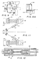
- FIGURE 11 illustrates the mechanism for sliding the boom seat assembly 23 along the base 20.
- Each boom seat 24 and 25 is mounted on its respective beam 18 for sliding motion along the beam in a manner described in greater detail hereinafter.
- a linear winch 70 is associated with each boom seat 24 and 25 to move the boom seat along its respective beam.
- FIGURE 11 illustrates the reeving of the linear winches.
- One end of a first linear winch cable 72 is secured a dead end on boom seat 24 and is reeved between a skid base sheave assembly 74 rigidly secured at the forward end of the base 20 and a boom seat sheave assembly 76 mounted on boom seat 24.
- the cable extends from the boom seat sheave assembly about a skid base horizontal sheave 78 and through linear winch 70.
- the cable passes through the winch 70 for take-up on a storage reel 80.
- the winch 70 includes a pair of jaws 82 and a pair of jaws 84.
- a cable such as cable 72, passes through both pairs of jaws through the linear winch 70.
- the winch 70 has hydraulic mechanisms which permit each pair of jaws to be moved along the frame of the winch 70 in the direction the cable extends.
- a pair of jaws clamps the cable and the jaws are then moved along the winch to pay in or pay out the cable as desired. Near the end of travel of the clamping pair of jaws, the other pair of jaws is used to clamp the cable and release the cable from the first pair of jaws.
- the storage reel 80 needs only sufficient power to wrap the non- tensioned cable thereon or pay out the non-tensioned cable therefrom.
- the use of such linear winches 70 greatly reduces wear on the cable and permits the cable to have a much longer life than simply taking in or paying out a cable under tension from a conventional winch.
- the boom seat 25 is similarly reeved to another linear winch 70 as seen in FIGURE 11.
- the linear winches can pull the boom seat assembly 23 from the stowed configuration, as seen in FIGURE 5, to the lifting configuration, as seen in FIGURE 1.
- the weight of the boom will cause the boom seat assembly 23 to move to the stowage configuration as the cable 72 are paid out from the storage reels through the linear winches 70.
- FIGURES 8 and 9 illustrate portions of boom seat 25.
- boom seat 24 is substantially identical in all functional respects.
- the boom seat 25 is provided with a clevis 86 mounted on base 88.
- Clevis 86 supports pin 90 which pivotally secures one leg of the boom to the boom seat.
- Parallel rails 92 are bolted to the base 88 on opposite sides of the base.
- Each rail 92 has a notch 94 which receives a portion of the top of a beam 18 to guide the boom seat along the beam.
- a plurality of adjustment bolts 96 are threaded horizontally through the rails to bear against a vertical surface of beam 18 to insure that the motion of the boom seat is along the length of the beam.
- the adjustable bolt 96 is secured in the desired adjustment position by nut 98 and lock washer 100.
- a series of bolts 102 are threaded from the bottom of the rail to effectively adjust the height of the notch 94 to prevent tipping of the boom seat.
- a spud pin assembly 104 is mounted on the boom seat 25 which includes a spud pin 106 and a mechanism for engaging the spud pin 106 with the beam 18 in the stowed and lifting configurations to rigidly secure each boom seat relative to the base 20.
- the spud pin is raised to permit sliding motion along the top of the beam 18.
- Each backleg 30 is made up of four telescoping tubes 108, 110, 112, and 114 of increasing diameter.
- a bottom lug 116 is pivotally mounted to base 20 at the rear of the base and secured to the lower end of tube 108.
- An inner reinforcement ring 118 forms the upper end of tube 108 and mounts a plurality of friction reducing members 120 on its outer surface to provide a low friction engagement between the upper end of tube 108 and the inner surface of the next larger tube 110.
- Members 120 are preferably formed of blocks of a nylon material referred to by the trademark NYLATRON.
- a series of stop blocks 122 are mounted on the inner surface of tube 110 and bear against the ring 118 to limit the shortening of the backleg 30 in the stowed configuration as seen in FIGURE 10.
- the tube 110 When telescoped outward to the lifting position, the tube 110 will slide over tube 108 until an exterior annular stop ring 124 on tube 108 engages an interior annular stop ring 126 on tube 110.
- the smaller diameter tubes 108, 110 and 112 are each provided with inner reinforcement rings 118 with friction reducing members 120 to cooperate with stop blocks 122 on the next larger tubes 110, 112 and 114, respectively to set the minimum length of the backleg 30 so that it serves the function of a rest for mast 26.
- Each of the three larger diameter tubes, tubes 110, 112, and 114 are provided with exterior reinforcement rings 128 at their lower end proximate the bottom lug 116 which also mounts friction reducing members 120 to bear against the outer surface of the next smaller tube along which the given tube will telescope.
- the smaller three tubes 108, 110 and 112 each have an outer annular stop ring 124 and the larger diameter tubes 110, 112 and 114 have interior annular stop rings 126 for limiting the total extending length of the backleg 30.
- a top lug 130 is secured at the upper end of the largest tube 114 for pivotal attachment near the top of the mast 26.
- the present inven strictlytion provides an improved crane which has significant advantages over prior crane designs.
- the crane can be readily reconfigured from a lifting configuration for lifting large heavy loads to a stowed configuration, minimizing height dimensions of the crane and improving its seaworthiness.
- the invention provides for stowage of the boom along the length of the base 20 to provide maximum stability in the stowed configuration.
- Towers 132 mounted near the front of the base 20 can pivot inward to support the weight of the front of the boom near the main block.
- the use of the backleg assembly 28 provides an efficient tension carrying assembly between the back of the base of the crane and mast 26 and also acts to support the mast in the stowed position to eliminate the need for a separate mast rest.
- the crane achieves one of the advantages found in a rotating base crane by permitting the boom to be stored essentially within the confines of the base of the crane, without the necessity for complex and expensive rotation mounting structure and a dedicated support structure, such a barge, specifically adapted to receive the rotating base crane.
Landscapes
- Engineering & Computer Science (AREA)
- Mechanical Engineering (AREA)
- Jib Cranes (AREA)
Applications Claiming Priority (2)
| Application Number | Priority Date | Filing Date | Title |
|---|---|---|---|
| US90525186A | 1986-09-08 | 1986-09-08 | |
| US905251 | 1986-09-08 |
Publications (2)
| Publication Number | Publication Date |
|---|---|
| EP0260112A2 true EP0260112A2 (de) | 1988-03-16 |
| EP0260112A3 EP0260112A3 (de) | 1988-09-21 |
Family
ID=25420495
Family Applications (1)
| Application Number | Title | Priority Date | Filing Date |
|---|---|---|---|
| EP87307934A Withdrawn EP0260112A3 (de) | 1986-09-08 | 1987-09-08 | Demontierbare Kranstruktur |
Country Status (2)
| Country | Link |
|---|---|
| EP (1) | EP0260112A3 (de) |
| JP (1) | JPS6374894A (de) |
Cited By (2)
| Publication number | Priority date | Publication date | Assignee | Title |
|---|---|---|---|---|
| US20100294737A1 (en) * | 2008-02-07 | 2010-11-25 | Blokhuis, S.E.D. | Crane vessel |
| CN114072350A (zh) * | 2019-05-03 | 2022-02-18 | 伊特里克公司 | 紧凑型悬臂起重机 |
Families Citing this family (1)
| Publication number | Priority date | Publication date | Assignee | Title |
|---|---|---|---|---|
| AU2021216432B2 (en) | 2020-02-06 | 2024-09-05 | Noble Rig Holdings Limited | Hoist apparatus for mobile offshore platform |
Family Cites Families (9)
| Publication number | Priority date | Publication date | Assignee | Title |
|---|---|---|---|---|
| FR875775A (fr) * | 1941-10-07 | 1942-10-02 | Perfectionnement aux grues pour navires | |
| DE872832C (de) * | 1949-04-21 | 1953-04-09 | Guenther Dr-Ing Lehmann | Schwimmkran |
| DE860703C (de) * | 1950-10-07 | 1952-12-22 | Aug Kloenne Fa | Kran, insbesondere Schwimmkran |
| DE927470C (de) * | 1952-05-09 | 1955-05-09 | Demag Ag | Schwimmkran |
| FI44770C (fi) * | 1969-11-11 | 1971-12-10 | Kone Oy | Laivanosturi. |
| US3977530A (en) * | 1974-06-13 | 1976-08-31 | The Manitowoc Company, Inc. | Crane with gantry backhitch and boom hoist assembly removable as a unit |
| US4194638A (en) * | 1978-06-07 | 1980-03-25 | The Manitowoc Company, Inc. | Ring supported tower crane |
| GB2088822B (en) * | 1980-12-10 | 1984-08-08 | Triplett James Thomas | Floating crane apparatus |
| IT1160249B (it) * | 1983-12-27 | 1987-03-04 | Cdf Ss | Apparecchiatura semovente di sollevamento |
-
1987
- 1987-09-08 JP JP22512287A patent/JPS6374894A/ja active Pending
- 1987-09-08 EP EP87307934A patent/EP0260112A3/de not_active Withdrawn
Cited By (3)
| Publication number | Priority date | Publication date | Assignee | Title |
|---|---|---|---|---|
| US20100294737A1 (en) * | 2008-02-07 | 2010-11-25 | Blokhuis, S.E.D. | Crane vessel |
| US8701904B2 (en) * | 2008-02-07 | 2014-04-22 | Itrec B.V. | Crane vessel |
| CN114072350A (zh) * | 2019-05-03 | 2022-02-18 | 伊特里克公司 | 紧凑型悬臂起重机 |
Also Published As
| Publication number | Publication date |
|---|---|
| JPS6374894A (ja) | 1988-04-05 |
| EP0260112A3 (de) | 1988-09-21 |
Similar Documents
| Publication | Publication Date | Title |
|---|---|---|
| US6729804B1 (en) | Cantilevered tower for jack-up platform | |
| CN103231998B (zh) | 一种具有提升起重机的船只 | |
| EP0944548B1 (de) | Hebe vorrichtung | |
| US3889818A (en) | Extensible crane | |
| US6591770B1 (en) | Boating lift | |
| US6491174B1 (en) | Inverted pedestal crane | |
| US12378099B2 (en) | Heave compensated dual hoist crane | |
| CN117227901B (zh) | 拖轮用伸缩式起抛锚装置以及拖轮 | |
| US4492310A (en) | Apparatus and method for loading and unloading cargo lighters on or from ships | |
| US5265741A (en) | Boom extension for gantry cranes | |
| EP0260112A2 (de) | Demontierbare Kranstruktur | |
| CN100506634C (zh) | 一种引导船舶上的缆索的牵引栓装置 | |
| CN114072350B (zh) | 紧凑型悬臂起重机 | |
| US3658187A (en) | Marine cargo handling crane | |
| EP0406394A1 (de) | Kran für behälter | |
| US11975803B2 (en) | Hoist apparatus for mobile offshore platform | |
| US20150122760A1 (en) | Jackup pedestal crane installation and operation, movable along a guide | |
| CA2109301C (en) | Apparatus for offshore swivel replacement | |
| WO2024235817A1 (en) | Telescopic boom and crane, vessel and method comprising such a boom | |
| WO1986000608A1 (en) | Crane for heavy loads, in particular offshore crane, and process for the mooring of a crane | |
| EP4735327A1 (de) | Kranvorrichtung mit a-rahmen | |
| CN117403864A (zh) | 一种用于自升式钻井平台桩腿维护的吊篮装置 | |
| JPH0553718B2 (de) | ||
| JPH02127398A (ja) | 舟艇揚降装置 |
Legal Events
| Date | Code | Title | Description |
|---|---|---|---|
| PUAI | Public reference made under article 153(3) epc to a published international application that has entered the european phase |
Free format text: ORIGINAL CODE: 0009012 |
|
| AK | Designated contracting states |
Kind code of ref document: A2 Designated state(s): DE FR GB IT NL SE |
|
| PUAL | Search report despatched |
Free format text: ORIGINAL CODE: 0009013 |
|
| AK | Designated contracting states |
Kind code of ref document: A3 Designated state(s): DE FR GB IT NL SE |
|
| 17P | Request for examination filed |
Effective date: 19890321 |
|
| 17Q | First examination report despatched |
Effective date: 19900212 |
|
| RAP1 | Party data changed (applicant data changed or rights of an application transferred) |
Owner name: AMCLYDE ENGINEERED PRODUCTS, INC. (A DELAWARE CORP |
|
| STAA | Information on the status of an ep patent application or granted ep patent |
Free format text: STATUS: THE APPLICATION IS DEEMED TO BE WITHDRAWN |
|
| 18D | Application deemed to be withdrawn |
Effective date: 19900823 |
|
| RIN1 | Information on inventor provided before grant (corrected) |
Inventor name: BLAIR, JERRY A. Inventor name: COPP, BRUCE A. Inventor name: FREDSTROM, ROBERT A. |