EP0260136B1 - Appareil pour réactions chimiques - Google Patents
Appareil pour réactions chimiques Download PDFInfo
- Publication number
- EP0260136B1 EP0260136B1 EP87308002A EP87308002A EP0260136B1 EP 0260136 B1 EP0260136 B1 EP 0260136B1 EP 87308002 A EP87308002 A EP 87308002A EP 87308002 A EP87308002 A EP 87308002A EP 0260136 B1 EP0260136 B1 EP 0260136B1
- Authority
- EP
- European Patent Office
- Prior art keywords
- tubes
- conveyor
- capillary
- tube
- liquid
- Prior art date
- Legal status (The legal status is an assumption and is not a legal conclusion. Google has not performed a legal analysis and makes no representation as to the accuracy of the status listed.)
- Expired
Links
- 238000006243 chemical reaction Methods 0.000 title claims abstract description 53
- 239000003153 chemical reaction reagent Substances 0.000 claims abstract description 39
- 239000007788 liquid Substances 0.000 claims description 68
- 238000005406 washing Methods 0.000 claims description 27
- 239000000126 substance Substances 0.000 claims description 19
- 238000012360 testing method Methods 0.000 claims description 15
- 238000007599 discharging Methods 0.000 claims description 3
- 102000004190 Enzymes Human genes 0.000 description 36
- 108090000790 Enzymes Proteins 0.000 description 36
- 239000000243 solution Substances 0.000 description 36
- 238000000034 method Methods 0.000 description 18
- 239000011324 bead Substances 0.000 description 13
- MHAJPDPJQMAIIY-UHFFFAOYSA-N Hydrogen peroxide Chemical compound OO MHAJPDPJQMAIIY-UHFFFAOYSA-N 0.000 description 12
- 230000036046 immunoreaction Effects 0.000 description 10
- 230000003287 optical effect Effects 0.000 description 9
- 239000000758 substrate Substances 0.000 description 9
- 102100023635 Alpha-fetoprotein Human genes 0.000 description 7
- 102100025475 Carcinoembryonic antigen-related cell adhesion molecule 5 Human genes 0.000 description 7
- GEYOCULIXLDCMW-UHFFFAOYSA-N 1,2-phenylenediamine Chemical compound NC1=CC=CC=C1N GEYOCULIXLDCMW-UHFFFAOYSA-N 0.000 description 6
- 101000914324 Homo sapiens Carcinoembryonic antigen-related cell adhesion molecule 5 Proteins 0.000 description 6
- 101000914321 Homo sapiens Carcinoembryonic antigen-related cell adhesion molecule 7 Proteins 0.000 description 6
- 230000002494 anti-cea effect Effects 0.000 description 6
- 238000004519 manufacturing process Methods 0.000 description 6
- 229920003023 plastic Polymers 0.000 description 5
- 239000004033 plastic Substances 0.000 description 5
- 102000003992 Peroxidases Human genes 0.000 description 4
- 239000008280 blood Substances 0.000 description 4
- 210000004369 blood Anatomy 0.000 description 4
- 238000003018 immunoassay Methods 0.000 description 4
- 108040007629 peroxidase activity proteins Proteins 0.000 description 4
- XLYOFNOQVPJJNP-UHFFFAOYSA-N water Substances O XLYOFNOQVPJJNP-UHFFFAOYSA-N 0.000 description 4
- 239000011248 coating agent Substances 0.000 description 3
- 238000000576 coating method Methods 0.000 description 3
- 238000001035 drying Methods 0.000 description 3
- 239000011521 glass Substances 0.000 description 3
- 230000005484 gravity Effects 0.000 description 3
- 239000000463 material Substances 0.000 description 3
- 230000007246 mechanism Effects 0.000 description 3
- 239000013307 optical fiber Substances 0.000 description 3
- 230000000717 retained effect Effects 0.000 description 3
- 239000000853 adhesive Substances 0.000 description 2
- 230000001070 adhesive effect Effects 0.000 description 2
- QVGXLLKOCUKJST-UHFFFAOYSA-N atomic oxygen Chemical compound [O] QVGXLLKOCUKJST-UHFFFAOYSA-N 0.000 description 2
- 238000005266 casting Methods 0.000 description 2
- 238000003759 clinical diagnosis Methods 0.000 description 2
- 238000005259 measurement Methods 0.000 description 2
- 239000000203 mixture Substances 0.000 description 2
- 239000001301 oxygen Substances 0.000 description 2
- 229910052760 oxygen Inorganic materials 0.000 description 2
- 230000035484 reaction time Effects 0.000 description 2
- 238000003756 stirring Methods 0.000 description 2
- 108010022366 Carcinoembryonic Antigen Proteins 0.000 description 1
- 239000004698 Polyethylene Substances 0.000 description 1
- 108010026331 alpha-Fetoproteins Proteins 0.000 description 1
- 239000000427 antigen Substances 0.000 description 1
- 102000036639 antigens Human genes 0.000 description 1
- 108091007433 antigens Proteins 0.000 description 1
- 238000013459 approach Methods 0.000 description 1
- 238000011161 development Methods 0.000 description 1
- 235000012489 doughnuts Nutrition 0.000 description 1
- 230000000694 effects Effects 0.000 description 1
- 238000002474 experimental method Methods 0.000 description 1
- 239000000835 fiber Substances 0.000 description 1
- 238000007654 immersion Methods 0.000 description 1
- 230000000984 immunochemical effect Effects 0.000 description 1
- 239000012535 impurity Substances 0.000 description 1
- 238000002347 injection Methods 0.000 description 1
- 239000007924 injection Substances 0.000 description 1
- 238000012423 maintenance Methods 0.000 description 1
- 238000010137 moulding (plastic) Methods 0.000 description 1
- -1 polyethylene Polymers 0.000 description 1
- 229920000573 polyethylene Polymers 0.000 description 1
- 229920005749 polyurethane resin Polymers 0.000 description 1
- 238000011160 research Methods 0.000 description 1
- 210000002700 urine Anatomy 0.000 description 1
- 238000003466 welding Methods 0.000 description 1
Images


Classifications
-
- B—PERFORMING OPERATIONS; TRANSPORTING
- B01—PHYSICAL OR CHEMICAL PROCESSES OR APPARATUS IN GENERAL
- B01L—CHEMICAL OR PHYSICAL LABORATORY APPARATUS FOR GENERAL USE
- B01L9/00—Supporting devices; Holding devices
- B01L9/06—Test-tube stands; Test-tube holders
- B01L9/065—Test-tube stands; Test-tube holders specially adapted for capillary tubes
-
- G—PHYSICS
- G01—MEASURING; TESTING
- G01N—INVESTIGATING OR ANALYSING MATERIALS BY DETERMINING THEIR CHEMICAL OR PHYSICAL PROPERTIES
- G01N35/00—Automatic analysis not limited to methods or materials provided for in any single one of groups G01N1/00 - G01N33/00; Handling materials therefor
- G01N35/02—Automatic analysis not limited to methods or materials provided for in any single one of groups G01N1/00 - G01N33/00; Handling materials therefor using a plurality of sample containers moved by a conveyor system past one or more treatment or analysis stations
-
- G—PHYSICS
- G01—MEASURING; TESTING
- G01N—INVESTIGATING OR ANALYSING MATERIALS BY DETERMINING THEIR CHEMICAL OR PHYSICAL PROPERTIES
- G01N35/00—Automatic analysis not limited to methods or materials provided for in any single one of groups G01N1/00 - G01N33/00; Handling materials therefor
- G01N2035/00178—Special arrangements of analysers
- G01N2035/00237—Handling microquantities of analyte, e.g. microvalves, capillary networks
-
- G—PHYSICS
- G01—MEASURING; TESTING
- G01N—INVESTIGATING OR ANALYSING MATERIALS BY DETERMINING THEIR CHEMICAL OR PHYSICAL PROPERTIES
- G01N35/00—Automatic analysis not limited to methods or materials provided for in any single one of groups G01N1/00 - G01N33/00; Handling materials therefor
- G01N35/02—Automatic analysis not limited to methods or materials provided for in any single one of groups G01N1/00 - G01N33/00; Handling materials therefor using a plurality of sample containers moved by a conveyor system past one or more treatment or analysis stations
- G01N35/04—Details of the conveyor system
- G01N2035/0401—Sample carriers, cuvettes or reaction vessels
- G01N2035/0406—Individual bottles or tubes
-
- G—PHYSICS
- G01—MEASURING; TESTING
- G01N—INVESTIGATING OR ANALYSING MATERIALS BY DETERMINING THEIR CHEMICAL OR PHYSICAL PROPERTIES
- G01N35/00—Automatic analysis not limited to methods or materials provided for in any single one of groups G01N1/00 - G01N33/00; Handling materials therefor
- G01N35/02—Automatic analysis not limited to methods or materials provided for in any single one of groups G01N1/00 - G01N33/00; Handling materials therefor using a plurality of sample containers moved by a conveyor system past one or more treatment or analysis stations
- G01N35/04—Details of the conveyor system
- G01N2035/046—General conveyor features
- G01N2035/0465—Loading or unloading the conveyor
Definitions
- the aforementioned apparatus for performing a reaction in capillary tubes has an advantage in that a small volume sample is adequate to be useful as compared with the conventional apparatus.
- the capillary tubes are always conveyed while being held in a horizontal position by the conveying device while specimen, reagent or the like are fed to the interior of the tubes from the feeding device. If the reagent and the like contacts the ends of the capillary tubes, it is instantaneously charged into the tubes. At this moment, the capillary tubes are held substantially horizontal so that the force of gravity which tends to cause the liquid in the tube to drop from the tubes is smaller than the force of the surface tension by virtue of which the liquid is retained in the tubes. As a result, the reagent and the like may remain in a stable condition while being charged into the entire length of each of the tubes. Each capillary tube may therefore if desired be supplied with the same volume (equal to the internal volume of the tube) of the reagent or the like.
- a plurality of said capillary tubes may be held in parallel with each other by said conveying means, or they may be held in a radial arrangement. Preferably they are held at a fixed distance by said conveying means.
- the apparatus may be adapted for use with capillary tubes previously coated with an immunoreactive substance, said feeding means for said reagent and the like being adapted to feed the specimen and reagent to the interior of each of said capillary tubes after predetermined intervals.
- light-transmission windows are provided in the sheet at portions over which the capillary tubes overlap; these may be individual windows or a light-transmission slit extending continuously across portions over which a set of capillary tubes overlaps.
- a corresponding division, aperture or windows may be provided in the conveyor if necessary to allow the light beam to pass.
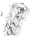
- Fig. 1 is a perspective view of an apparatus according to an embodiment of the invention, wherein numeral 1 is a belt conveyor adapted for use as a device for conveying a plurality of capillary tubes 2 and comprises a drive shaft 12 driven by a motor 11 with a reduction gear, a driven shaft 13 rotatably supported on a body of the apparatus, the two shafts 12, 13 being mounted on the apparatus at opposite ends thereof, and an endless conveyor belt 16 of material such as polyurethane resin trained in parallel fashion over pulleys 14 and 15 mounted on the respective shafts 12, 13.
- numeral 1 is a belt conveyor adapted for use as a device for conveying a plurality of capillary tubes 2 and comprises a drive shaft 12 driven by a motor 11 with a reduction gear, a driven shaft 13 rotatably supported on a body of the apparatus, the two shafts 12, 13 being mounted on the apparatus at opposite ends thereof, and an endless conveyor belt 16 of material such as polyurethane resin trained in parallel fashion over pulleys 14 and 15 mounted on the respective
- the capillary tubes drop from the hopper 18 by the force of gravity and are indexed one by one to be fed to each of the grooves 17 on the top surface of the belt where they are held in place. Then, the tubes are carried on and conveyed by the conveyor belt 16.
- a casing 19 is provided downwardly of the neighborhood of one end of the drive shaft 12 for the belt conveyor 1 for receiving the processed capillary tubes.
- the fully processed capillary tubes drop from the right end of the conveyor belt 16 and are successively received in the casing 19. No specific provision or operation or the like is required for demounting the tubes 2 from the belt conveyor 1.
- Numeral 3 designates a feeding device for reagent and the like which is disposed along the belt conveyor 1 and which feeds a liquid specimen to be examined and an immunoassay reagent solution and the like to the interior of the tubes 2.
- the reagent feeding device comprises a supplying station 20 for supplying the successively different liquid specimens to be examined, a liquid specimen washing station 30 for washing the interior of each tube 2 after a predetermined time and for discharging the reacted liquid specimen, an enzyme labelled antibody solution supplying station 40 for feeding an immunoassay reagent solution such as an enzyme labelled antibody solution into each tube 2, a reagent washing station 50 for discharging any enzyme labelled antibody solution which has not bonded upon washing the interior of each tube 2 after a predetermined time, and an enzyme substrate solution supplying station 60 for feeding an enzyme substrate solution into each tube 2.
- These stations are successively arranged along the conveyor belt 16.
- the capillary tubes 2 are held substantially horizontal so that the force of gravity by which the liquid in the tubes 2 would tend to flow from the interior of the tubes is smaller than the force of the surface tension by which the liquid is retained in the tubes.
- the liquid specimen is stable in a charged condition along the full length of the tubes 2.
- a constant volume (equivalent to the internal volume of the tubes) is always supplied to and charged in the tubes 2.
- FIG. 3 which shows the liquid specimen washing station 30 in section
- Suction pipes 31 connected to a suction device are disposed on one side of the conveyor belt 16 and in the proximity thereof such as not to contact the tube 2. With this non-contact arrangement, no impurities are attached to the tubes, thereby ensuring that an accurate reaction is performed.
- a cylinder 32 for containing washing liquid is provided on the other side of the conveyor belt 16 and forms drops at the lower end of the cylinder 32.
- the capillary tubes 2 are filled with washing liquid by a capillary phenomenon when the ends of the tubes contact the drops.
- the enzyme labelled antibody solution supplying station 40 is provided with a cylinder 42 similar to the washing liquid cylinder 32 on one side of the conveyor belt 16.
- the capillary tubes 2 as washed are filled with the enzyme labelled antibody solution by a capillary phenomenon.
- the enzyme labelled antibody solution is in a stable condition while the tubes 2 are filled with the antibody solution over the entire length thereof, thereby always supplying and charging a constant volume (equivalent to the internal volume of the tubes) into the tubes 2.
- the enzyme substrate solution supplying station 60 is of the same structure as that of the enzyme labelled antibody solution supplying station 40 and is adapted to charge an enzyme substrate solution into the capillary tubes 2.
- the tubes 2 are always filled and supplied with a constant volume (equivalent to the internal volume of the tubes) of the enzyme substrate solution.
- Numeral 7 is a measuring device which is disposed such as to cover the conveyor belt 16 in the proximity of the right end thereof for measuring the optical density of the reactive solution in each tube 2.
- a spectrophotometer, a fluorophotometer or the like may be used as the measuring device.
- the antigen concentration in the liquid specimen is calculated by a microcomputer on the basis of the optical density of the reactive solution.
- Numeral 72 is an indicator for digitally displaying the result of the measurement.
- the capillary tubes 2 are adapted to allow the anti-CEA antibody to be coated to their interior surfaces and are put in the hopper 18.
- the liquid specimen is contained in each liquid specimen cylinder 22 and is mounted on the feeder device 21 of the liquid specimen supplying station 20.
- the capillary tubes 2 at the liquid specimen supplying station 20 are filled with the liquid specimen so that the CEA contained in the specimen are bonded to the anti-CEA antibody coated to the inner surface of each tube 2, thereby performing the immunoreaction.
- a mixture solution of hydrogen peroxide and orthophenylenediamine is charged into each tube 2 so that oxygen which is formed from hydrogen peroxide by the enzyme (peroxidase) of the enzyme labelled antibody coated in each tube 2 reacts with the orthophenylenediamine whereby the reactive solution produces a color.
- an anti-AFP antibody as the immunoreactive substance
- an enzyme labelled anti-AFP antibody as the enzyme labelled antibody
- hydrogen peroxide as the enzyme substrate
- orthophenylenediamine as the color producing reagent
- peroxidase as the labelled enzyme
- a mixture solution of hydrogen peroxide and orthophenylenediamine is charged into each tube 2 so that oxygen which is formed from hydrogen peroxide by the enzyme (peroxidase) of the enzyme labelled antibody coated in each tube 2 reacts on orthophenylenediamine to cause the liquid to produce a color.
- the colored capillary tubes 2 are moved to the measuring device 7 after the lapse of a predetermined time (for instance, 10 min.) and then the result of the reaction is read from the tubes by a chromometer.
- a predetermined time for instance, 10 min.
- the value of what is read is computed by a microcomputer and the like and is digitally displayed by, for instance, an indicator 72.
- the capillary tubes 2 which have been subjected to all the processes drop from the right end of the conveyor belt 16 and are successively received in the casing.
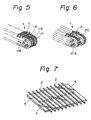
- Figs. 5 and 6 show a modified form of a belt conveyor used as the conveyor device.
- perforations 118 are formed on the bottoms of grooves 117 in a conveyor belt 116 to allow the beam to pass through the perforations as shown in Fig. 5.
- a pair of conveyor belts 216 with the tubes 2 carried thereon are spaced away from each other in parallel therewith to allow the measuring beam to pass through clearances defined by the belts and tubes as shown in Fig. 6.
- a plurality of the tubes 2 may be arranged in parallel with each other on a sheet 4 and the like made of paper or plastic and may be bonded, mounted or joined by an adhesive or any other suitable means. This will enable one to enter various legends, displays and records in the sheet for convenience of practical use.
- Numeral 5 is an aperture through which the measuring beam passes.
- the belt conveyor is used in this embodiment as a conveyor device, the invention is not limited thereto.
- a disc 301 in the doughnut form for rotating the conveyor device may be provided on its surface with radial grooves 317 to carry the tubes 2 thereon. 318 is a rotating shaft.
- a plurality of the capillary tubes may be radially mounted on the sheet in advance.
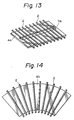
- the chemical reaction apparatus as shown in Figs. 9 and 10, may use another form of a conveyor apparatus in which a circular rotary member 401 is rotatable upon the horizontal axis and is provided on its periphery with grooves 417 to receive therein the capillary tubes 2 to be conveyed.
- the capillary tubes are horizontally held to perform the chemical reaction so that the volumes of reagent and the like which are supplied to and filled in the tubes for use in reaction are always constant thereby performing a very accurate chemical reaction without requiring any metering device. Accordingly, the apparatus may be simplified to not only reduce production costs but also enable anyone to readily use it thereby facilitating maintenance of the apparatus. Advantages derived from the instant apparatus are in that either the device for holding the tubes in the conveyor device or another device for demounting the tubes is very simple in structure and operation for convenience to its use. Thus, the chemical reaction apparatus may be obtained which is suitable for automatic chemical reaction and is ready for use.
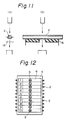
- Fig. 12 there is shown a back side of the sheet fixedly mounted with the capillary tubes.
- a surface side of the sheet 4 made from paper or plastic materials there are fitted a plurality of (for example, ten, as illustrated in the drawing) capillary tubes so that they are aligned to each other with equal distances therebetween and so that their both ends extend outwardly a little from the sheet 4.
- the capillary tubes are same in their shapes and sizes, and are coated at their inner front surfaces with an immunoreactive substance. While the tubes 2 are fixed onto the sheet 4 in this invention most commonly by an adhesive, they may be fixed by any other conventional means such as heat welding, or they may be made integral with the sheet 4 by means of an integral plastic molding method.
- Fig. 14 there are shown the plurality of capillary tubes 2 which are aligned to each other with an equal angular distance on a fan-like shaped sheet 4b.
- This kind of arrangement of capillary tubes can advantageously be employed in connection with the conveying device shown in Fig. 8.
Landscapes
- Chemical & Material Sciences (AREA)
- Health & Medical Sciences (AREA)
- General Health & Medical Sciences (AREA)
- Life Sciences & Earth Sciences (AREA)
- Analytical Chemistry (AREA)
- Biochemistry (AREA)
- Physics & Mathematics (AREA)
- General Physics & Mathematics (AREA)
- Immunology (AREA)
- Pathology (AREA)
- Clinical Laboratory Science (AREA)
- Chemical Kinetics & Catalysis (AREA)
- Automatic Analysis And Handling Materials Therefor (AREA)
- Physical Or Chemical Processes And Apparatus (AREA)
- Steering Control In Accordance With Driving Conditions (AREA)
Claims (9)
- Appareil pour réaliser des réactions chimiques dans une pluralité de tubes capillaires (2), caractérisé en ce qu'il comprend un convoyeur (16, 116, 216, 301 401) pour supporter les tubes capillaires (2) et les transporter suivant une orientation sensiblement horizontale au delà de moyens d'alimentation (3) pour fournir un liquide destiné à être repris par les tubes (2) sur le convoyeur pour une réaction chimique, lesdits moyens d'alimentation (3) étant disposés de façon à fournir des gouttes suspendues dudit liquide avec lesquelles les extrémités des tubes capillaires horizontaux (2) sur le convoyeur sont mises en contact, grâce à quoi les tubes sont sensiblement remplis par action capillaire.
- Appareil suivant la revendication 1, caractérisé en ce que les moyens d'alimentation (3) comprennent un poste (20) d'alimentation d'échantillons pour fournir des échantillons de liquide à tester aux tubes respectifs (2), et au moins un poste de fourniture de réactif (40, 60), espacé sur le convoyeur depuis le poste d'alimentation en échantillons pour fournir des réactifs de liquide ou analogues.
- Appareil suivant la revendication 1 ou la revendication 2, comprenant des moyens de lavage (31) pour décharger le liquide d'un tube capillaire sur le convoyeur.
- Appareil suivant la revendication 2 et la revendication 3, comprenant des moyens de commande grâce auxquels des échantillons de liquide peuvent être déchargés depuis leurs tubes respectifs (2) par lesdits moyens de lavage (31) après un temps prédéterminé de réaction avec une substance immunoréactive revêtue sur lesdits tubes (2), et un réactif introduit subséquemment dans les tubes (2) audit poste (40, 60) d'alimentation en réactif.
- Appareil suivant l'une des revendications précédentes, caractérisé en ce que le convoyeur (16, 116, 216, 301, 401) possède une série de rainures espacées (17, 117, 317, 417) pour recevoir les tubes respectifs (2).
- Appareil suivant l'une des revendications 1 à 4 comprenant une pluralité de tubes capillaires (2) montés en série de manière fixe avec un alignement mutuel prédéterminé sur une feuille (4, 4a, 5a).
- Appareil suivant l'une des revendications précédentes caractérisé en ce que le convoyeur est un convoyeur à bande (16).
- Appareil suivant l'une quelconque des revendications précédentes comprenant des moyens pour mesurer les propriétés d'une solution réactionnelle dans un tube capillaire (2) sur le convoyeur.
- Appareil suivant la revendication 8 caractérisé en ce qu'au moins une fenêtre de transmission de lumière (118, 5, 5a) est prévue pour permettre à un faisceau lumineux de test de passer transversalement au travers du tube (2) pour ladite mesure.
Priority Applications (1)
| Application Number | Priority Date | Filing Date | Title |
|---|---|---|---|
| AT87308002T ATE69892T1 (de) | 1986-09-11 | 1987-09-10 | Apparatur fuer chemische reaktionen. |
Applications Claiming Priority (4)
| Application Number | Priority Date | Filing Date | Title |
|---|---|---|---|
| JP61214521A JPH067918B2 (ja) | 1986-09-11 | 1986-09-11 | 化学反応装置 |
| JP214521/86 | 1986-09-11 | ||
| JP1987039030U JPH0356256Y2 (fr) | 1987-03-16 | 1987-03-16 | |
| JP39030/87U | 1987-03-16 |
Publications (3)
| Publication Number | Publication Date |
|---|---|
| EP0260136A2 EP0260136A2 (fr) | 1988-03-16 |
| EP0260136A3 EP0260136A3 (en) | 1989-04-19 |
| EP0260136B1 true EP0260136B1 (fr) | 1991-11-27 |
Family
ID=26378341
Family Applications (1)
| Application Number | Title | Priority Date | Filing Date |
|---|---|---|---|
| EP87308002A Expired EP0260136B1 (fr) | 1986-09-11 | 1987-09-10 | Appareil pour réactions chimiques |
Country Status (7)
| Country | Link |
|---|---|
| US (1) | US4960566A (fr) |
| EP (1) | EP0260136B1 (fr) |
| AT (1) | ATE69892T1 (fr) |
| AU (1) | AU582501B2 (fr) |
| CA (1) | CA1289856C (fr) |
| DE (1) | DE3774810D1 (fr) |
| ES (1) | ES2028095T3 (fr) |
Cited By (1)
| Publication number | Priority date | Publication date | Assignee | Title |
|---|---|---|---|---|
| EP3370066B1 (fr) * | 2015-10-28 | 2022-04-27 | Boditech Med Inc. | Appareil de type à écoulement horizontal pour le transport automatique de cartouches de réactif |
Families Citing this family (33)
| Publication number | Priority date | Publication date | Assignee | Title |
|---|---|---|---|---|
| EP0388224A3 (fr) * | 1989-03-17 | 1991-05-22 | Seiko Instruments Inc. | Procédé et dispositif de traitement chimique |
| JPH0394828A (ja) * | 1989-09-05 | 1991-04-19 | Mochida Pharmaceut Co Ltd | 反応容器着脱装置および固相と液相との反応装置 |
| JPH06501099A (ja) * | 1990-09-11 | 1994-01-27 | ヴォアヒーズ・テクノロジース・インコーポレーテッド | 被覆された毛管 |
| FI923220A7 (fi) * | 1992-07-14 | 1994-01-15 | Wallac Oy | Menetelmä ja laitteisto näytteen käsittelemiseksi sekä näytteenkeräysjärjestelmä |
| US5580523A (en) * | 1994-04-01 | 1996-12-03 | Bard; Allen J. | Integrated chemical synthesizers |
| US20050042149A1 (en) * | 1994-04-01 | 2005-02-24 | Integrated Chemical Synthesizers, Inc. | Nanoscale chemical synthesis |
| US5785926A (en) * | 1995-09-19 | 1998-07-28 | University Of Washington | Precision small volume fluid processing apparatus |
| AU715627B2 (en) * | 1996-02-21 | 2000-02-03 | Biomerieux Vitek, Inc. | Automatic sample testing machine |
| WO1998037397A1 (fr) * | 1997-02-21 | 1998-08-27 | University Of Washington | Dispositif de melange commande par actionneur piezo-ceramique |
| US6102249A (en) * | 1997-02-21 | 2000-08-15 | University Of Washington | Jam resistant dispenser for capillary tubes and the like |
| DE19846466A1 (de) * | 1998-10-08 | 2000-04-27 | Ghs Gesundheits Service Ag | Analyseverfahren zur simultanen Bestimmung von Parametern aus unterschiedlichen Medien |
| US6375817B1 (en) | 1999-04-16 | 2002-04-23 | Perseptive Biosystems, Inc. | Apparatus and methods for sample analysis |
| US6555389B1 (en) * | 1999-05-11 | 2003-04-29 | Aclara Biosciences, Inc. | Sample evaporative control |
| DE19935634A1 (de) * | 1999-07-29 | 2001-02-01 | Hirschmann Laborgeraete Gmbh | Mittel zum Handhaben, Transportieren und Lagern von Kapillaren, Verfahren zu dessen Herstellung und Spender zum Vereinzeln der Kapillaren von einem solchen Mittel |
| US6423536B1 (en) * | 1999-08-02 | 2002-07-23 | Molecular Dynamics, Inc. | Low volume chemical and biochemical reaction system |
| CA2420041A1 (fr) * | 2000-09-07 | 2002-03-14 | Tibotec Bvba | Remplissage de capillaires |
| US20050063869A1 (en) * | 2003-09-24 | 2005-03-24 | Stephane Follonier | Device, system and method of detecting targets in a fluid sample |
| DE102004062280A1 (de) * | 2003-12-29 | 2005-07-28 | Siemens Ag | Verfahren und Vorrichtung zum Dispensieren von Flüssigkeiten im Mikroraster |
| DE102004043399A1 (de) * | 2004-09-03 | 2006-03-09 | Bioplan Consulting Gmbh | Anlage zur Behandlung mikrobiologischer Proben |
| US8021611B2 (en) * | 2005-04-09 | 2011-09-20 | ProteinSimple | Automated micro-volume assay system |
| US7850917B2 (en) * | 2008-03-11 | 2010-12-14 | Ortho-Clinical Diagnostics, Inc. | Particle agglutination in a tip |
| EP2895868B1 (fr) | 2012-09-14 | 2018-05-30 | Beckman Coulter, Inc. | Système analytique avec transport capillaire |
| WO2016210420A1 (fr) | 2015-06-26 | 2016-12-29 | Abbott Laboratories | Dispositif d'échangeur de cuve de réaction pour un analyseur de diagnostic |
| US10890593B2 (en) * | 2015-10-09 | 2021-01-12 | Sysmex Corporation | Test piece mounting body, transport unit, and test piece analyzer |
| WO2018111765A1 (fr) | 2016-12-12 | 2018-06-21 | xCella Biosciences, Inc. | Procédés et systèmes de criblage à l'aide de réseaux microcapillaires |
| US11085039B2 (en) | 2016-12-12 | 2021-08-10 | xCella Biosciences, Inc. | Methods and systems for screening using microcapillary arrays |
| JP7208902B2 (ja) | 2016-12-30 | 2023-01-19 | エクセラ・バイオサイエンシーズ・インコーポレイテッド | マルチステージサンプル回収システム |
| US12318775B2 (en) | 2018-12-06 | 2025-06-03 | xCella Biosciences, Inc. | Lateral loading of microcapillary arrays |
| CN110297098B (zh) * | 2019-07-30 | 2020-12-01 | 成都斯马特科技有限公司 | 一种全自动化学发光免疫分析仪用毛细管送管装置 |
| CN110261632B (zh) * | 2019-07-30 | 2024-05-14 | 成都斯马特科技股份有限公司 | 一种全自动化学发光免疫分析仪 |
| CN110514858B (zh) * | 2019-08-21 | 2024-06-18 | 成都斯马特科技股份有限公司 | 一种全自动化学发光免疫分析用试剂包装置 |
| CN110514859B (zh) * | 2019-08-21 | 2021-03-16 | 成都斯马特科技有限公司 | 一种全自动化学发光免疫分析方法 |
| CN111337481B (zh) * | 2020-04-26 | 2024-07-09 | 成都斯马特科技股份有限公司 | 一种化学发光免疫分析仪 |
Family Cites Families (14)
| Publication number | Priority date | Publication date | Assignee | Title |
|---|---|---|---|---|
| FR1493438A (fr) * | 1966-04-05 | 1967-09-01 | Massiot Philips Sa | Appareil d'analyse d'échantillons liquides |
| US3607097A (en) * | 1967-08-09 | 1971-09-21 | Philips Corp | Analyzer for liquid samples |
| US3859051A (en) * | 1973-08-16 | 1975-01-07 | Rohe Scientific Corp | Means for transferring a liquid in a capillary open at both ends to an analyzing system |
| CH568793A5 (fr) * | 1974-02-15 | 1975-11-14 | Mettler Instrumente Ag | |
| US3918908A (en) * | 1974-05-17 | 1975-11-11 | Geomet | Method for prothrombin testing |
| US4052161A (en) * | 1974-08-22 | 1977-10-04 | The Perkin-Elmer Corporation | Kinetic analyzer |
| NL176841C (nl) * | 1975-03-04 | 1985-06-17 | Philips Nv | Transport inrichting voor testmonsterdragers, alsmede deze dragers. |
| US4058367A (en) * | 1976-05-19 | 1977-11-15 | Gilford Instrument Laboratories Inc. | Automatic asynchronous fluid processing apparatus |
| FR2397636A1 (fr) * | 1977-07-15 | 1979-02-09 | Gist Brocades Nv | Instrument pour analyses chimiques et microbiologiques |
| US4349510A (en) * | 1979-07-24 | 1982-09-14 | Seppo Kolehmainen | Method and apparatus for measurement of samples by luminescence |
| JPS5836631A (ja) * | 1981-08-27 | 1983-03-03 | Mochida Pharmaceut Co Ltd | 固相と液相との反応方法及び装置 |
| AU556898B2 (en) * | 1981-09-25 | 1986-11-27 | Commonwealth Serum Laboratories Commission | Capillary based rotomat for immunoassays |
| NZ201901A (en) * | 1981-09-25 | 1986-11-12 | Commw Serum Lab Commission | An apparatus suitable for performing automated heterogeneous immunoassays in a plurality of samples |
| JPS61114731A (ja) * | 1984-11-10 | 1986-06-02 | Mochida Pharmaceut Co Ltd | 化学反応装置 |
-
1987
- 1987-08-18 CA CA000544781A patent/CA1289856C/fr not_active Expired - Lifetime
- 1987-08-19 US US07/087,646 patent/US4960566A/en not_active Expired - Fee Related
- 1987-08-21 AU AU77372/87A patent/AU582501B2/en not_active Ceased
- 1987-09-10 EP EP87308002A patent/EP0260136B1/fr not_active Expired
- 1987-09-10 ES ES198787308002T patent/ES2028095T3/es not_active Expired - Lifetime
- 1987-09-10 DE DE8787308002T patent/DE3774810D1/de not_active Expired - Fee Related
- 1987-09-10 AT AT87308002T patent/ATE69892T1/de not_active IP Right Cessation
Cited By (1)
| Publication number | Priority date | Publication date | Assignee | Title |
|---|---|---|---|---|
| EP3370066B1 (fr) * | 2015-10-28 | 2022-04-27 | Boditech Med Inc. | Appareil de type à écoulement horizontal pour le transport automatique de cartouches de réactif |
Also Published As
| Publication number | Publication date |
|---|---|
| US4960566A (en) | 1990-10-02 |
| AU582501B2 (en) | 1989-03-23 |
| ATE69892T1 (de) | 1991-12-15 |
| CA1289856C (fr) | 1991-10-01 |
| EP0260136A3 (en) | 1989-04-19 |
| EP0260136A2 (fr) | 1988-03-16 |
| AU7737287A (en) | 1988-03-17 |
| DE3774810D1 (de) | 1992-01-09 |
| ES2028095T3 (es) | 1992-07-01 |
Similar Documents
| Publication | Publication Date | Title |
|---|---|---|
| EP0260136B1 (fr) | Appareil pour réactions chimiques | |
| EP0329183B1 (fr) | Procédé et dispositif d'analyse avec possibilité de mélange | |
| US4774055A (en) | Automatic analysis apparatus | |
| JP3393131B2 (ja) | 自動分析機 | |
| US4340390A (en) | Method and apparatus for metering biological fluids | |
| US4683120A (en) | Biological fluid assay system | |
| EP0417305A1 (fr) | Analyseur d'echantillon de liquide et procede d'analyse d'echantillon de liquide utilisant ledit analyseur | |
| JPH08506893A (ja) | サンプル用ウェルの形状と一致する担体を用いる固相イムノアッセイ | |
| CA2021054A1 (fr) | Methode et dispositif d'analyse automatique de plusieurs specimens d'essai | |
| KR900002254B1 (ko) | 화학반응장치 | |
| EP0301743B1 (fr) | Analyseur avec station de lavage séparée de l'incubateur | |
| US8507280B2 (en) | Method of normalizing surface tension of a sample fluid | |
| US5324479A (en) | Analyzer for the determination of the phenotype and the ABO blood group | |
| EP0336309A2 (fr) | Appareil d'analyses à accès sélectif ou séquentiel pour analyses clinico-chimiques et tests immunologiques | |
| JPH067918B2 (ja) | 化学反応装置 | |
| WO2007129740A1 (fr) | Dispositif de reapprovisionnement en reactif | |
| JPS6188158A (ja) | 自動分析装置 | |
| JP2533843B2 (ja) | 免疫学的分析に用いられる担体収納容器 | |
| JPH01287465A (ja) | 液体を攪拌し得る分析装置および分析方法 | |
| JPH0356256Y2 (fr) | ||
| JPH0843407A (ja) | 自動化学分析装置 | |
| JPH06288916A (ja) | 生化学分析方法 | |
| JPH09292398A (ja) | 自動化学分析装置 | |
| JPS61262639A (ja) | 自動分析装置 | |
| JPS6319520A (ja) | 液面検出装置 |
Legal Events
| Date | Code | Title | Description |
|---|---|---|---|
| PUAI | Public reference made under article 153(3) epc to a published international application that has entered the european phase |
Free format text: ORIGINAL CODE: 0009012 |
|
| AK | Designated contracting states |
Kind code of ref document: A2 Designated state(s): AT DE ES FR GB IT NL |
|
| PUAL | Search report despatched |
Free format text: ORIGINAL CODE: 0009013 |
|
| AK | Designated contracting states |
Kind code of ref document: A3 Designated state(s): AT DE ES FR GB IT NL |
|
| 17P | Request for examination filed |
Effective date: 19890915 |
|
| 17Q | First examination report despatched |
Effective date: 19910131 |
|
| GRAA | (expected) grant |
Free format text: ORIGINAL CODE: 0009210 |
|
| AK | Designated contracting states |
Kind code of ref document: B1 Designated state(s): AT DE ES FR GB IT NL |
|
| REF | Corresponds to: |
Ref document number: 69892 Country of ref document: AT Date of ref document: 19911215 Kind code of ref document: T |
|
| REF | Corresponds to: |
Ref document number: 3774810 Country of ref document: DE Date of ref document: 19920109 |
|
| ITF | It: translation for a ep patent filed | ||
| ET | Fr: translation filed | ||
| REG | Reference to a national code |
Ref country code: ES Ref legal event code: FG2A Ref document number: 2028095 Country of ref document: ES Kind code of ref document: T3 |
|
| PLBE | No opposition filed within time limit |
Free format text: ORIGINAL CODE: 0009261 |
|
| STAA | Information on the status of an ep patent application or granted ep patent |
Free format text: STATUS: NO OPPOSITION FILED WITHIN TIME LIMIT |
|
| 26N | No opposition filed | ||
| PGFP | Annual fee paid to national office [announced via postgrant information from national office to epo] |
Ref country code: GB Payment date: 19940831 Year of fee payment: 8 |
|
| PGFP | Annual fee paid to national office [announced via postgrant information from national office to epo] |
Ref country code: DE Payment date: 19940908 Year of fee payment: 8 |
|
| PGFP | Annual fee paid to national office [announced via postgrant information from national office to epo] |
Ref country code: FR Payment date: 19940909 Year of fee payment: 8 |
|
| PGFP | Annual fee paid to national office [announced via postgrant information from national office to epo] |
Ref country code: AT Payment date: 19940913 Year of fee payment: 8 |
|
| PGFP | Annual fee paid to national office [announced via postgrant information from national office to epo] |
Ref country code: NL Payment date: 19940930 Year of fee payment: 8 Ref country code: ES Payment date: 19940930 Year of fee payment: 8 |
|
| PG25 | Lapsed in a contracting state [announced via postgrant information from national office to epo] |
Ref country code: GB Effective date: 19950910 Ref country code: AT Effective date: 19950910 |
|
| PG25 | Lapsed in a contracting state [announced via postgrant information from national office to epo] |
Ref country code: ES Free format text: LAPSE BECAUSE OF THE APPLICANT RENOUNCES Effective date: 19950911 |
|
| PG25 | Lapsed in a contracting state [announced via postgrant information from national office to epo] |
Ref country code: NL Effective date: 19960401 |
|
| GBPC | Gb: european patent ceased through non-payment of renewal fee |
Effective date: 19950910 |
|
| PG25 | Lapsed in a contracting state [announced via postgrant information from national office to epo] |
Ref country code: FR Effective date: 19960531 |
|
| PG25 | Lapsed in a contracting state [announced via postgrant information from national office to epo] |
Ref country code: DE Effective date: 19960601 |
|
| NLV4 | Nl: lapsed or anulled due to non-payment of the annual fee |
Effective date: 19960401 |
|
| REG | Reference to a national code |
Ref country code: FR Ref legal event code: ST |
|
| REG | Reference to a national code |
Ref country code: ES Ref legal event code: FD2A Effective date: 19991007 |
|
| PG25 | Lapsed in a contracting state [announced via postgrant information from national office to epo] |
Ref country code: IT Free format text: LAPSE BECAUSE OF NON-PAYMENT OF DUE FEES Effective date: 20050910 |