EP0260667A1 - Compresseur à plateau en biais avec mécanisme à déplacement variable - Google Patents
Compresseur à plateau en biais avec mécanisme à déplacement variable Download PDFInfo
- Publication number
- EP0260667A1 EP0260667A1 EP87113499A EP87113499A EP0260667A1 EP 0260667 A1 EP0260667 A1 EP 0260667A1 EP 87113499 A EP87113499 A EP 87113499A EP 87113499 A EP87113499 A EP 87113499A EP 0260667 A1 EP0260667 A1 EP 0260667A1
- Authority
- EP
- European Patent Office
- Prior art keywords
- valve
- compressor
- plate type
- type compressor
- suction chamber
- Prior art date
- Legal status (The legal status is an assumption and is not a legal conclusion. Google has not performed a legal analysis and makes no representation as to the accuracy of the status listed.)
- Granted
Links
- 238000006073 displacement reaction Methods 0.000 title abstract description 11
- 230000008878 coupling Effects 0.000 claims description 6
- 238000010168 coupling process Methods 0.000 claims description 6
- 238000005859 coupling reaction Methods 0.000 claims description 6
- 238000005057 refrigeration Methods 0.000 claims description 5
- 238000001816 cooling Methods 0.000 abstract description 4
- 239000010687 lubricating oil Substances 0.000 abstract description 4
- 238000004891 communication Methods 0.000 description 7
- 230000000994 depressogenic effect Effects 0.000 description 6
- 238000010276 construction Methods 0.000 description 3
- 230000002093 peripheral effect Effects 0.000 description 3
- 238000006243 chemical reaction Methods 0.000 description 2
- 239000012530 fluid Substances 0.000 description 2
- 238000007789 sealing Methods 0.000 description 2
- 238000004378 air conditioning Methods 0.000 description 1
- 230000007423 decrease Effects 0.000 description 1
- 238000005192 partition Methods 0.000 description 1
- 239000003507 refrigerant Substances 0.000 description 1
Images


Classifications
-
- F—MECHANICAL ENGINEERING; LIGHTING; HEATING; WEAPONS; BLASTING
- F04—POSITIVE - DISPLACEMENT MACHINES FOR LIQUIDS; PUMPS FOR LIQUIDS OR ELASTIC FLUIDS
- F04B—POSITIVE-DISPLACEMENT MACHINES FOR LIQUIDS; PUMPS
- F04B25/00—Multi-stage pumps
- F04B25/04—Multi-stage pumps having cylinders coaxial with, or parallel or inclined to, main shaft axis
-
- F—MECHANICAL ENGINEERING; LIGHTING; HEATING; WEAPONS; BLASTING
- F04—POSITIVE - DISPLACEMENT MACHINES FOR LIQUIDS; PUMPS FOR LIQUIDS OR ELASTIC FLUIDS
- F04B—POSITIVE-DISPLACEMENT MACHINES FOR LIQUIDS; PUMPS
- F04B27/00—Multi-cylinder pumps specially adapted for elastic fluids and characterised by number or arrangement of cylinders
- F04B27/08—Multi-cylinder pumps specially adapted for elastic fluids and characterised by number or arrangement of cylinders having cylinders coaxial with, or parallel or inclined to, main shaft axis
- F04B27/14—Control
- F04B27/16—Control of pumps with stationary cylinders
- F04B27/18—Control of pumps with stationary cylinders by varying the relative positions of a swash plate and a cylinder block
- F04B27/1804—Controlled by crankcase pressure
- F04B2027/1809—Controlled pressure
- F04B2027/1813—Crankcase pressure
-
- F—MECHANICAL ENGINEERING; LIGHTING; HEATING; WEAPONS; BLASTING
- F04—POSITIVE - DISPLACEMENT MACHINES FOR LIQUIDS; PUMPS FOR LIQUIDS OR ELASTIC FLUIDS
- F04B—POSITIVE-DISPLACEMENT MACHINES FOR LIQUIDS; PUMPS
- F04B27/00—Multi-cylinder pumps specially adapted for elastic fluids and characterised by number or arrangement of cylinders
- F04B27/08—Multi-cylinder pumps specially adapted for elastic fluids and characterised by number or arrangement of cylinders having cylinders coaxial with, or parallel or inclined to, main shaft axis
- F04B27/14—Control
- F04B27/16—Control of pumps with stationary cylinders
- F04B27/18—Control of pumps with stationary cylinders by varying the relative positions of a swash plate and a cylinder block
- F04B27/1804—Controlled by crankcase pressure
- F04B2027/1822—Valve-controlled fluid connection
- F04B2027/1831—Valve-controlled fluid connection between crankcase and suction chamber
-
- F—MECHANICAL ENGINEERING; LIGHTING; HEATING; WEAPONS; BLASTING
- F04—POSITIVE - DISPLACEMENT MACHINES FOR LIQUIDS; PUMPS FOR LIQUIDS OR ELASTIC FLUIDS
- F04B—POSITIVE-DISPLACEMENT MACHINES FOR LIQUIDS; PUMPS
- F04B27/00—Multi-cylinder pumps specially adapted for elastic fluids and characterised by number or arrangement of cylinders
- F04B27/08—Multi-cylinder pumps specially adapted for elastic fluids and characterised by number or arrangement of cylinders having cylinders coaxial with, or parallel or inclined to, main shaft axis
- F04B27/14—Control
- F04B27/16—Control of pumps with stationary cylinders
- F04B27/18—Control of pumps with stationary cylinders by varying the relative positions of a swash plate and a cylinder block
- F04B27/1804—Controlled by crankcase pressure
- F04B2027/184—Valve controlling parameter
- F04B2027/1845—Crankcase pressure
-
- F—MECHANICAL ENGINEERING; LIGHTING; HEATING; WEAPONS; BLASTING
- F04—POSITIVE - DISPLACEMENT MACHINES FOR LIQUIDS; PUMPS FOR LIQUIDS OR ELASTIC FLUIDS
- F04B—POSITIVE-DISPLACEMENT MACHINES FOR LIQUIDS; PUMPS
- F04B27/00—Multi-cylinder pumps specially adapted for elastic fluids and characterised by number or arrangement of cylinders
- F04B27/08—Multi-cylinder pumps specially adapted for elastic fluids and characterised by number or arrangement of cylinders having cylinders coaxial with, or parallel or inclined to, main shaft axis
- F04B27/14—Control
- F04B27/16—Control of pumps with stationary cylinders
- F04B27/18—Control of pumps with stationary cylinders by varying the relative positions of a swash plate and a cylinder block
- F04B27/1804—Controlled by crankcase pressure
- F04B2027/184—Valve controlling parameter
- F04B2027/1859—Suction pressure
Definitions
- the present invention relates to a slant plate type compressor for use in a refrigerant compressor, and more particularly, to a slant plate type compressor, such as wobble plate type compressor, with a variable displacement mechanism suitable for use in an automotive air conditioning system.
- the slant angle of the slant surface is determined by the pressure condition in the crank chamber.
- the pressure condition in the crank chamber is controlled in the following manner: the crank chamber communicates with the suction chamber through an aperture formed within a cylinder block, and the opening and closing of the aperture is controlled by a valve mechanism.
- the valve mechanism generally includes a bellows and a needle valve, and is located in the suction chamber so that the bellows operates in accordance with changes of pressure in the suction chamber.
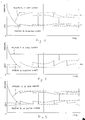
- the pressure in the suction chamber is controlled by the valve mechanism to maintain the change of pressure within small range SR1 as shown in Fig. 3. Therefore, if the predetermined pressure value in the suction chamber is determined to be lower than a pressure limit value Pa, there is possibility of generating frost on an evaporator. Thus, a predetermined pressure value P1 in suction chamber should be determined higher than the pressure limit value Pa so as to prevent frosting on the evaporator. As a result, a capacity adjusting mechanism starts its operation to control the capacity of the compressor at a higher pressure level than the pressure value Pa, the characteristic for the cooling down of the above compressor is thus inferior to that of the same type compressor without a variable displacement mechanism.
- the lubricating oil contained in the crank chamber may flow out to a refrigeration circuit through the suction chamber and cylinders. This lubricating oil existing in the refrigeration circuit causes the reduction of the heat-exchanging ratio of the evaporator.
- Roberts et al. 3,861,829 discloses the capacity adjusting mechanism used in a wobble plate type compressor.
- the wobble plate is disposed at a slant or inclination or inclination angle relative to the drive axis, and nutates but does not rotate, and drivingly couples the pistons to the drive source.
- This type of capacity adjusting mechanism using selective fluid communication between the crank chamber and the suction chamber, however, can be used in any type of compressor which uses a slanted plate or surface in the drive mechanism.
- U.S. Patent No. 4,664,604 issued to Terauchi, discloses this type of capacity adjusting mechanism in a swash plate type compressor.
- the swash plate like the wobble plate, is disposed at a slant angle and drivingly couples the pistons to the drive source.
- the wobble plate only nutates
- the swash plate both nutates and rotates.
- the term slant type compressor will therefore be used herein to refer to any type of compressor, including wobble and swash plate types, which use a slanted plate or surface in the drive mechanism.
- a slant plate type compressor for use in a refrigeration circuit comprises a compressor housing having a central portion, a front end plate at one end and a rear end plate at its other end.
- the housing has a cylinder block which is provided with a plurality of cylinders and a crank chamber adjacent the cylinder block.
- a piston is slidably fitted within each of the cylinders.
- a drive mechanism is coupled to the pistons to reciprocate the pistons within the cylinders.
- the drive mechanism includes a drive shaft which is rotatably supported in the housing, a rotor which is coupled to the drive shaft and is rotatable therewith.
- a coupling mechanism drivingly couples the rotor to the pistons such that the rotary motion of the rotor is converted into reciprocating motion of the pistons.
- the coupling mechanism includes a member which has a surface disposed at an inclination angle relative to the drive shaft. The inclination angle of the member is adjustable to vary the stroke length of the pistons and the capacity of the compressor.
- the rear end plate has a suction chamber and a discharge chamber. A passageway is connected between the crank chamber and the suction chamber.
- a valve mechanism controls the closing and opening of the passageway to vary the capacity of the compressor by while adjusting the inclination angle.
- the valve mechanism includes a valve element to directly control the closing and opening of the passageway, a first valve control device to control the movement of the valve element in accordance with the pressure condition in the crank chammber, and a second valve control device to control the movement of the valve element in accordance with the pressure condition in the suction chamber.
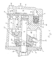
- a compressor 1 includes a closed housing assembly formed by a cylindrical housing 2, a front end plate 3 and a rear end plate in the form of a cylinder head 4.
- a cylinder block 21 and a crank chamber 22 are formed in the compressor housing 2.
- the front end plate 3 is attched to one end surface of the compressor housing 2, and the cylinder head 4 is fixed on one end surface of the cylinder block 21 through a valve plate 5.
- An opening 32 is formed in the central portion of the front end plate 3 to be penetrated by a drive shaft 6.
- the drive shaft 6 is rotatably supported within the front end plate 3 through a bearing 7.
- a shaft seal (not shown) is disposed between the inner surface of the opening 31 and the outer surface of the drive shaft 6 at the outside of the bearing 7.
- An inner end portion of the drive shaft 6 also extends into a central bore 23 formed in the central portion of the cylinder block 21 and is rotatably supported therein through a bearing 8.
- a rotor 9, which is disposed in the interior of the crank chamber 22, is connected to the drive shaft 6 and engages with an inclined plate 10 through a hinge portion 90. The inclination angle of the inclined plate 10 with respect to the drive shaft 6 can be adjusted by the hinge portion 90.
- a wobble plate 11 is disposed on the other side surface of the inclined plate 10 and bears against it through a bearing 12.
- a plurality of clinders 24, one of which is shown in Fig. 1, are equiangularly formed in the cylinder block 21, and a piston 13 is reciprocatably disposed within each cylinder 24.
- Each piston 13 is connected to the wobble plate 11 through a connecting rod 14, i.e., one end of each connecting rod 14 is connected to the wobble plate 11 with a ball joint and the other end of each connecting rod 14 is connected to one of the pistons 13 with a ball joint.
- a guide bar 15 extends within the crank chamber 22 of the compressor housing 2. The lower end portion of the wobble plate 11 engages the guide bar 15 to enable the wobble plate 11 to reciprocate along the guide bar 15 while preventing rotating motion.
- the pistons 13 are thus reciprocated within the cylinders 24 by a drive mechanism formed of the drive shaft 6, the rotor 9, the inclined plate 10, the wobble plate 11 and the connecting rods 14. If the drive shaft 6 and the rotor 9 are rotated, the inclined plate 11, the wobble plate 12 and the connecting rods 14 function as a coupling mechanism to convert the rotating motion of the rotor 9 into a reciprocating motion of the pistons 13.
- the cylinder head 4 is divided in its interior space into at least two chambers, such as a suction chamber 40 and a discharge chamber 41 by a partition wall 44, both of which communicate with the cylinders 24 through suction holes 50 or discharge holes 51 formed through the valve plate 5, respectively. Also, the cylinder head 4 is provided with an inlet port 42 and an outlet port 43 which place the suction chamber 40 and th e discharge chamber 41 to be in fluid communication with a refrigeration circuit.
- a passageway 25 is formed within the cylinder block 21 to communicate between the crank chamber 22 and the suction chamber 40 through a hollow portion 26, which is also formed within the cylinder block 21.
- a valve control mechanism 17 is located in the hollow portion 26.
- the mechanism 17 comprises a cup-shaped casing 171, a bellows 172 which serves as a first pressure sensing portion and is disposed within the casing 171 and a valve element 173 which serves as a second presure sensing portion.
- the casing 171 is fixedly disposed within the hollow portion 26 and an 0-ring 174 is disposed on the outer peripheral surface of the casing 171 to accomplish the sealing between the casing 171 and the hollow portin 26 to thereby obstruct the communication between the passageway 25 and the suction chamber 40 through a gap between the inner surface of the hollow portion 26 and the outer peripheral surface of the casing 171.
- the casing 171 is provided with an opening 171a at the outer peripheral surface to connect the passageway 25 with the interior of the casing 171 and a hole 171b at the bottom portion thereof.
- a screw thread portion is formed in the hole 171b to receive an adjusting screw 172a of the bellows 172.
- the bellows 172 includes the adjusting screw 172a to adjust the operating point thereof and a bellows element 172b within which a coil spring 172c is disposed for determining the operating point thereof.
- the adjusting screw 172a is attached to one end portion of the bellows element 172b.
- the valve element 173 comprises an operating valve 173a which is attached to the other end portion of the bellows element 172b and a valve seat 173b which is fixed on the opening portion of the casing 171.
- a guide pin 173c is attached to the end surface of the operating valve 173a to guide the axial movement of the bellows 172.
- a depressed portion 173d is formed on the valve seat 173b at the opposite side of the suction chamber 40 to define a suction pressure acting area.
- a hole 173e is formed through the valve seat 173b to communicate between the suction chamber 40 and the depressed portion 173d, and a hole 173f is also formed through valve seat 173b to be penetrated by the guide pin 173c of the operating valve 173a.
- the reaction force F of the bellows 172 which is composed by the reaction force of the bellows element 172b and the recoil strength of the coil spring 172c is determined by the following equation.
- F (A1 - A2) ⁇ Pc + A2 ⁇ Ps ...(1)
- A1 is an effective sectinal area of the bellows element 172b
- A2 is an effective sectional area of the depressed portion 173d
- Pc is the pressure in the crank chamber
- Ps is the pressure in the suction chamber.
- the pressure Ps in the suction chamber 40 and the pressure Pc in the crank chamber 22 are greater than the amount of the recoil strength of the coil spring 172c and the stiffness of the bellows element 172b, i.e., the pressures Ps, Pc in the suction and crank chambers 40, 22 are greater than the operating point of the bellows 172. Therefore, the operating valve 173a is urged toward left to open the communication between the suction chamber 40 and the interior of the casing 171 through the depressed portion 173d and the hole 173e, to thereby accomplish the communication between the crank chamber 22 and the suction chamber 40. In that condition, the pressure Pc in the crank chamber 22 is maintained at the pressure Ps in the suction chamber 40.
- the bellows element 172b extends toward right (in Fig. 2) together with the operating valve 173a. Therefore, the end opening of the depressed portion 173d is closed by the operating valve 173a, and the communication between the crank chamber 22 and the suction chamber 40 is obstructed. At that time, the inclination angle of the inclined plate is maintained to be the same angle as previouly.
- the pressure Ps in the suction chamber 40 decreases in inverse proportion to the increase of the pressure Pc in the crank chamber until the suction pressure Ps reaches a predetermined pressure P3, which is between pressures P1 and P2, as shown in Fig. 5.
- the opening and closing operation of the operating valve 173a is controlled by the valve control mechanism 17 to satisfy the equation (1). That is, when the operatin valve 173 accomplishes the communication between suction chamber 40 and the interior of the casing 171 through the depressed portion 173d and the hole 173e, the pressure Pc in the crank chamber 22 becomes higher as the pressure Ps in the suction chamber 40 becomes lower as mentioned above.
- the pressure Pc in the crank chamber 22 is changed in accordance with the pressure Ps in the suction chamber 40 and the change ratio Pc/Ps is determined by A2/(A2 - A1).
- the opening and closing operation of the bellows 173 is efficiently repeated in accordance with the pressures Pc, Ps in crank and suction chambers 22, 40, respectively.
- FIG. 6 With reference to Fig. 6, the construction of a valve control mechanism 18 in accordance with another embodiment of this invention is shown.
- An operating valve 181a of a valve mechanism 181 is in the form of a sphere and the inner surface of an opening 181b of a valve seat 181c is formed conically to fit with the outer surface of the operating valve 181a. The sealing between the operating valve 181a and the opening 181b is improved.
Landscapes
- Engineering & Computer Science (AREA)
- Mechanical Engineering (AREA)
- General Engineering & Computer Science (AREA)
- Compressors, Vaccum Pumps And Other Relevant Systems (AREA)
Applications Claiming Priority (2)
| Application Number | Priority Date | Filing Date | Title |
|---|---|---|---|
| JP61217622A JPS6375371A (ja) | 1986-09-16 | 1986-09-16 | 容量可変圧縮機 |
| JP217622/86 | 1986-09-16 |
Publications (2)
| Publication Number | Publication Date |
|---|---|
| EP0260667A1 true EP0260667A1 (fr) | 1988-03-23 |
| EP0260667B1 EP0260667B1 (fr) | 1991-07-31 |
Family
ID=16707176
Family Applications (1)
| Application Number | Title | Priority Date | Filing Date |
|---|---|---|---|
| EP87113499A Expired - Lifetime EP0260667B1 (fr) | 1986-09-16 | 1987-09-15 | Compresseur à plateau en biais avec mécanisme à déplacement variable |
Country Status (6)
| Country | Link |
|---|---|
| US (1) | US4850810A (fr) |
| EP (1) | EP0260667B1 (fr) |
| JP (1) | JPS6375371A (fr) |
| KR (1) | KR950013012B1 (fr) |
| AU (1) | AU608243B2 (fr) |
| DE (1) | DE3771815D1 (fr) |
Cited By (2)
| Publication number | Priority date | Publication date | Assignee | Title |
|---|---|---|---|---|
| EP0581974A1 (fr) * | 1992-06-22 | 1994-02-09 | Sanden Corporation | Compresseur de réfrigération du type à plateau en biais avec mécanisme à déplacement variable |
| WO2005098235A1 (fr) * | 2004-03-17 | 2005-10-20 | Zexel Valeo Compressor Europe Gmbh | Compresseur, en particulier compresseur a pistons axiaux pour une installation de climatisation de vehicule |
Families Citing this family (9)
| Publication number | Priority date | Publication date | Assignee | Title |
|---|---|---|---|---|
| US4875834A (en) * | 1987-02-19 | 1989-10-24 | Sanden Corporation | Wobble plate type compressor with variable displacement mechanism |
| US5168716A (en) * | 1987-09-22 | 1992-12-08 | Sanden Corporation | Refrigeration system having a compressor with an internally and externally controlled variable displacement mechanism |
| US5189886A (en) * | 1987-09-22 | 1993-03-02 | Sanden Corporation | Refrigerating system having a compressor with an internally and externally controlled variable displacement mechanism |
| JP2945748B2 (ja) * | 1990-11-16 | 1999-09-06 | サンデン株式会社 | 容量可変型揺動式圧縮機 |
| AU644745B1 (en) * | 1992-07-08 | 1993-12-16 | Sanden Corporation | Slant plate type refrigerant compressor with variable displacement mechanism |
| JP4051134B2 (ja) | 1998-06-12 | 2008-02-20 | サンデン株式会社 | 可変容量圧縮機の容量制御弁機構 |
| JP4181274B2 (ja) | 1998-08-24 | 2008-11-12 | サンデン株式会社 | 圧縮機 |
| KR100340606B1 (ko) * | 1999-09-10 | 2002-06-15 | 이시카와 타다시 | 용량 가변형 압축기의 제어밸브 |
| JP6723148B2 (ja) * | 2016-12-01 | 2020-07-15 | サンデン・オートモーティブコンポーネント株式会社 | 可変容量圧縮機 |
Citations (2)
| Publication number | Priority date | Publication date | Assignee | Title |
|---|---|---|---|---|
| US4037993A (en) * | 1976-04-23 | 1977-07-26 | Borg-Warner Corporation | Control system for variable displacement compressor |
| GB2003991A (en) * | 1977-09-12 | 1979-03-21 | Borg Warner | Variable capacity wobble plate compressor |
Family Cites Families (21)
| Publication number | Priority date | Publication date | Assignee | Title |
|---|---|---|---|---|
| US2573863A (en) * | 1948-05-19 | 1951-11-06 | Alva E Mitchell | Compressor |
| US2964234A (en) * | 1954-05-13 | 1960-12-13 | Houdaille Industries Inc | Constant clearance volume compressor |
| US3810488A (en) * | 1972-11-20 | 1974-05-14 | Controls Co Of America | Pressure regulator valve |
| US3861829A (en) * | 1973-04-04 | 1975-01-21 | Borg Warner | Variable capacity wobble plate compressor |
| US4073603A (en) * | 1976-02-06 | 1978-02-14 | Borg-Warner Corporation | Variable displacement compressor |
| US4174191A (en) * | 1978-01-18 | 1979-11-13 | Borg-Warner Corporation | Variable capacity compressor |
| US4480964A (en) * | 1982-02-25 | 1984-11-06 | General Motors Corporation | Refrigerant compressor lubrication system |
| US4428718A (en) * | 1982-02-25 | 1984-01-31 | General Motors Corporation | Variable displacement compressor control valve arrangement |
| US4475871A (en) * | 1982-08-02 | 1984-10-09 | Borg-Warner Corporation | Variable displacement compressor |
| US4543043A (en) * | 1982-08-02 | 1985-09-24 | Borg-Warner Corporation | Variable displacement compressor |
| US4492527A (en) * | 1983-02-17 | 1985-01-08 | Diesel Kiki Co., Ltd. (Japanese Corp.) | Wobble plate piston pump |
| US4526516A (en) * | 1983-02-17 | 1985-07-02 | Diesel Kiki Co., Ltd. | Variable capacity wobble plate compressor capable of controlling angularity of wobble plate with high responsiveness |
| JPS60135680A (ja) * | 1983-12-23 | 1985-07-19 | Sanden Corp | 揺動式圧縮機 |
| JPS60162087A (ja) * | 1984-02-02 | 1985-08-23 | Sanden Corp | 容量制御型コンプレツサ装置 |
| JPS60175783A (ja) * | 1984-02-21 | 1985-09-09 | Sanden Corp | 容量可変型斜板式圧縮機 |
| JPH0637874B2 (ja) * | 1984-12-28 | 1994-05-18 | 株式会社豊田自動織機製作所 | 可変容量圧縮機 |
| JPS61176798A (ja) * | 1985-01-30 | 1986-08-08 | 鹿島建設株式会社 | 割岩検知装置 |
| US4688997A (en) * | 1985-03-20 | 1987-08-25 | Kabushiki Kaisha Toyoda Jidoshokki Seisakusho | Variable displacement compressor with variable angle wobble plate and wobble angle control unit |
| US4606705A (en) * | 1985-08-02 | 1986-08-19 | General Motors Corporation | Variable displacement compressor control valve arrangement |
| JPS62206277A (ja) * | 1986-03-06 | 1987-09-10 | Toyoda Autom Loom Works Ltd | 揺動斜板型圧縮機におけるワツブルプレ−トの揺動傾斜角戻し機構 |
| JPS6329067A (ja) * | 1986-07-21 | 1988-02-06 | Sanden Corp | 連続容量可変型揺動式圧縮機 |
-
1986
- 1986-09-16 JP JP61217622A patent/JPS6375371A/ja active Granted
-
1987
- 1987-09-11 AU AU78327/87A patent/AU608243B2/en not_active Ceased
- 1987-09-15 DE DE8787113499T patent/DE3771815D1/de not_active Expired - Lifetime
- 1987-09-15 EP EP87113499A patent/EP0260667B1/fr not_active Expired - Lifetime
- 1987-09-15 US US07/096,038 patent/US4850810A/en not_active Expired - Lifetime
- 1987-09-16 KR KR1019870010231A patent/KR950013012B1/ko not_active Expired - Lifetime
Patent Citations (2)
| Publication number | Priority date | Publication date | Assignee | Title |
|---|---|---|---|---|
| US4037993A (en) * | 1976-04-23 | 1977-07-26 | Borg-Warner Corporation | Control system for variable displacement compressor |
| GB2003991A (en) * | 1977-09-12 | 1979-03-21 | Borg Warner | Variable capacity wobble plate compressor |
Cited By (2)
| Publication number | Priority date | Publication date | Assignee | Title |
|---|---|---|---|---|
| EP0581974A1 (fr) * | 1992-06-22 | 1994-02-09 | Sanden Corporation | Compresseur de réfrigération du type à plateau en biais avec mécanisme à déplacement variable |
| WO2005098235A1 (fr) * | 2004-03-17 | 2005-10-20 | Zexel Valeo Compressor Europe Gmbh | Compresseur, en particulier compresseur a pistons axiaux pour une installation de climatisation de vehicule |
Also Published As
| Publication number | Publication date |
|---|---|
| EP0260667B1 (fr) | 1991-07-31 |
| AU7832787A (en) | 1988-03-24 |
| US4850810A (en) | 1989-07-25 |
| KR880004234A (ko) | 1988-06-07 |
| KR950013012B1 (ko) | 1995-10-24 |
| DE3771815D1 (de) | 1991-09-05 |
| AU608243B2 (en) | 1991-03-28 |
| JPH0229877B2 (fr) | 1990-07-03 |
| JPS6375371A (ja) | 1988-04-05 |
Similar Documents
| Publication | Publication Date | Title |
|---|---|---|
| US4905477A (en) | Refrigerant circuit with passageway control mechanism | |
| US4780060A (en) | Slant plate type compressor with variable displacement mechanism | |
| US4778348A (en) | Slant plate type compressor with variable displacement mechanism | |
| AU606345B2 (en) | Slant plate type compressor with variable displacement mechanism | |
| US4632640A (en) | Wobble plate type compressor with a capacity adjusting mechanism | |
| US4747753A (en) | Slant plate type compressor with variable displacement mechanism | |
| US4780059A (en) | Slant plate type compressor with variable capacity mechanism with improved cooling characteristics | |
| US4664604A (en) | Slant plate type compressor with capacity adjusting mechanism and rotating swash plate | |
| EP0172970B1 (fr) | Compresseur de réfrigérant | |
| US5823000A (en) | Refrigerant circuit with fluid flow control mechanism | |
| EP0318316A1 (fr) | Compresseur à plateau en biais avec mécanisme à déplacement variable | |
| EP0340024A1 (fr) | Compresseur du type à plateau en biais avec mécanisme à déplacement variable | |
| US6102670A (en) | Apparatus and method for operating fluid displacement apparatus with variable displacement mechanism | |
| US5277552A (en) | Slant plate type compressor with variable displacement mechanism | |
| EP0260667B1 (fr) | Compresseur à plateau en biais avec mécanisme à déplacement variable | |
| EP0300831A1 (fr) | Compresseur à plateau en biais avec mécanisme à déplacement variable | |
| EP0302325B1 (fr) | Compresseur à plateau oscillant avec refoulement variable | |
| EP0207613B1 (fr) | Compresseur à plateau oscillant à capacité variable | |
| US6350106B1 (en) | Variable displacement compressor with capacity control mechanism | |
| EP0318976A1 (fr) | Compresseur à plateau en biais avec mécanisme à déplacement variable | |
| EP0945618B1 (fr) | Soupape de contrôle de déplacement utilisée dans un compresseur à capacité variable | |
| EP0797000B1 (fr) | Dispositif de réduction de la charge de démarrage pour compresseur de réfrigérant | |
| EP0896154A2 (fr) | Compresseur à déplacement variable avec un passage entre la chambre de bielle et la chambre d'aspiration amélioré en relation avec la position de montage du compresseur |
Legal Events
| Date | Code | Title | Description |
|---|---|---|---|
| PUAI | Public reference made under article 153(3) epc to a published international application that has entered the european phase |
Free format text: ORIGINAL CODE: 0009012 |
|
| AK | Designated contracting states |
Kind code of ref document: A1 Designated state(s): DE FR GB IT SE |
|
| 17P | Request for examination filed |
Effective date: 19880303 |
|
| 17Q | First examination report despatched |
Effective date: 19880816 |
|
| GRAA | (expected) grant |
Free format text: ORIGINAL CODE: 0009210 |
|
| ITF | It: translation for a ep patent filed | ||
| AK | Designated contracting states |
Kind code of ref document: B1 Designated state(s): DE FR GB IT SE |
|
| ET | Fr: translation filed | ||
| REF | Corresponds to: |
Ref document number: 3771815 Country of ref document: DE Date of ref document: 19910905 |
|
| PLBE | No opposition filed within time limit |
Free format text: ORIGINAL CODE: 0009261 |
|
| STAA | Information on the status of an ep patent application or granted ep patent |
Free format text: STATUS: NO OPPOSITION FILED WITHIN TIME LIMIT |
|
| 26N | No opposition filed | ||
| EAL | Se: european patent in force in sweden |
Ref document number: 87113499.5 |
|
| PGFP | Annual fee paid to national office [announced via postgrant information from national office to epo] |
Ref country code: GB Payment date: 19960906 Year of fee payment: 10 |
|
| PGFP | Annual fee paid to national office [announced via postgrant information from national office to epo] |
Ref country code: SE Payment date: 19960917 Year of fee payment: 10 |
|
| PG25 | Lapsed in a contracting state [announced via postgrant information from national office to epo] |
Ref country code: GB Free format text: LAPSE BECAUSE OF NON-PAYMENT OF DUE FEES Effective date: 19970915 |
|
| PG25 | Lapsed in a contracting state [announced via postgrant information from national office to epo] |
Ref country code: SE Free format text: LAPSE BECAUSE OF NON-PAYMENT OF DUE FEES Effective date: 19970916 |
|
| GBPC | Gb: european patent ceased through non-payment of renewal fee |
Effective date: 19970915 |
|
| EUG | Se: european patent has lapsed |
Ref document number: 87113499.5 |
|
| PG25 | Lapsed in a contracting state [announced via postgrant information from national office to epo] |
Ref country code: IT Free format text: LAPSE BECAUSE OF NON-PAYMENT OF DUE FEES;WARNING: LAPSES OF ITALIAN PATENTS WITH EFFECTIVE DATE BEFORE 2007 MAY HAVE OCCURRED AT ANY TIME BEFORE 2007. THE CORRECT EFFECTIVE DATE MAY BE DIFFERENT FROM THE ONE RECORDED. Effective date: 20050915 |
|
| PGFP | Annual fee paid to national office [announced via postgrant information from national office to epo] |
Ref country code: DE Payment date: 20060907 Year of fee payment: 20 |
|
| PGFP | Annual fee paid to national office [announced via postgrant information from national office to epo] |
Ref country code: FR Payment date: 20060908 Year of fee payment: 20 |