EP0260834A2 - Cassette pour ruban d'impression - Google Patents
Cassette pour ruban d'impression Download PDFInfo
- Publication number
- EP0260834A2 EP0260834A2 EP87307576A EP87307576A EP0260834A2 EP 0260834 A2 EP0260834 A2 EP 0260834A2 EP 87307576 A EP87307576 A EP 87307576A EP 87307576 A EP87307576 A EP 87307576A EP 0260834 A2 EP0260834 A2 EP 0260834A2
- Authority
- EP
- European Patent Office
- Prior art keywords
- ribbon
- casing
- cartridge according
- oscillating
- arms
- Prior art date
- Legal status (The legal status is an assumption and is not a legal conclusion. Google has not performed a legal analysis and makes no representation as to the accuracy of the status listed.)
- Ceased
Links
Images

Classifications
-
- B—PERFORMING OPERATIONS; TRANSPORTING
- B41—PRINTING; LINING MACHINES; TYPEWRITERS; STAMPS
- B41J—TYPEWRITERS; SELECTIVE PRINTING MECHANISMS, i.e. MECHANISMS PRINTING OTHERWISE THAN FROM A FORME; CORRECTION OF TYPOGRAPHICAL ERRORS
- B41J32/00—Ink-ribbon cartridges
-
- B—PERFORMING OPERATIONS; TRANSPORTING
- B41—PRINTING; LINING MACHINES; TYPEWRITERS; STAMPS
- B41J—TYPEWRITERS; SELECTIVE PRINTING MECHANISMS, i.e. MECHANISMS PRINTING OTHERWISE THAN FROM A FORME; CORRECTION OF TYPOGRAPHICAL ERRORS
- B41J35/00—Other apparatus or arrangements associated with, or incorporated in, ink-ribbon mechanisms
- B41J35/20—Ink-ribbon shifts, e.g. for exposing print, for case-shift adjustment, for rendering ink ribbon inoperative
Definitions
- the present invention relates to a cartridge for a printing ribbon for a typewriter or other printer, for example of the type having a character-carrying disc, comprising a printing ribbon having a plurality of tracks which can be selected for the printing operation, a casing for the ribbon, a pair of terminal portions provided with guide elements between which an external run of the ribbon extends, the guide elements being movable relative to each other and with respect to the casing, for the selection of one of the tracks while maintaining uniform tension across the width of the ribbon.
- Such a cartridge is known from EP 0 118 238, in which the terminal portions are oscillating arms and in which the guide elements are integral with the arms, which oscillate to move the selected track into a position in front of the character-carrying disc.
- the guide elements co-operate with two corresponding control cams which are fixed with respect to the casing and which modify the inclination of the guide elements during the oscillation movement of the arms from the viewing position to the various heights involved in track selection.
- the tension of the ribbon in its various working conditions is thus kept constant across the width of the ribbon.
- the use of this known cartridge is particlarly advantageous in machines of the type referred to as 'daisywheel' machines in which the ribbon has a very small space between the platen roller and the daisywheel itself.
- the cartridge suffers from the disadvantage of impairing vision in the region of the line of typing adjacent to the control cams for the guide elements.
- the object of the present invention is therefore to provide a cartridge for a printing ribbon which is simple and reliable and which makes it possible for the ribbon always to be uniformly tensioned both in its rest position and in its various working positions and which permits optimum visibility for the line of typing.
- the cartridge according to the invention is characterised in the manner set forth in claim 1.
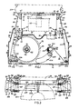
- the cartridge which is indicated generally by reference numeral 11 comprises a casing 12 of plastics material, which is of substantially parallelepipedic shape and which is designed to accommodate a typing or printing ribbon 13.
- the casing 12 comprises a bottom 14 and a series of walls 16, 17 and 18 which rearwardly define a space 19 for accommodating the upper part of a typing arrangement, for example a character-carrying disc 21 and a striker 22 which are disposed in front of a conventional platen roller 23 which defines a typing point 24 (see Figure 2).
- the character-carrying disc 21 ( Figure 1), the striker 22 and the roller 23 are known per se and are therefore shown diagrammatically by dash-dotted lines in the drawings.
- the casing 12 is closed upwardly by a cover 26 and is defined by a front wall 27 and side walls 28, 29, 31 and 32.
- the casing 12 comprises two arm portions 33 and 34 which project from the rear wall 17 and which have two openings 36 and 37 respectively arranged to accommodate a pair of oscillating arms, a right-hand arm 38 and a left-hand arm 39.
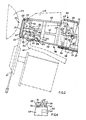
- Each oscillating arm 38 and 39 (see Figure 2) comprises a central portion 41 substantially perpendicular to the bottom 14, housed within the arm portions 33 and 34 and having a horizontal pin 42 parallel to the bottom 14, a series of ribs 43, 44, 45, 46, 47, 50 and 55 and two plate portions, an upper portion 48 and a lower portion 49, which taper towards the rear.
- Each oscillating arm 38 and 39 is in one piece and oscillates vertically by means of the pin 42 which is pivotally mounted in two seats 51 on two supports 52 projecting from the bottom 14 of the casing 12.
- Each oscillating arm 38 and 39 is of a very rigid structure capable of ensuring a predetermined degree of compactness and strength such as to prevent any flexing phenomena at the arms themselves.
- the spacing between the two supports 52 is such as to ensure only vertical oscillating movements at the respective oscillating arms 38 and 39, as can be clearly seen from the various Figures of drawings.
- a spring 53 fitted between a pin 54 on the central portion 41 and a stop 56 on the bottom 14 holds the respective oscillating arm 38 and 39 in the lowered position which permits viewing of the characters which have been printed along the line defined by the typing point 24.
- the spring 53 holds each oscillating arm 38 and 39 arrested against a shoulder 57 on the casing 12.
- the cartridge 11 can be removably fixed on a fixed support 58 of the typewriter in known manner, for example by means of two resilient plate members arranged to engage the appropriate seating portions 59 (see Figure 1) on the casing 12.
- the spring 53 (see Figure 2) holds the respective oscillating arm 58 and 39 in a condition of bearing with a suitably shaped element 61 against a lifting device 62.
- the device 62 comprises a pair of levers which are pivoted to the frame of the machine and which are controlled by a three-lobe cam for simultaneously raising the right-hand and left-hand oscillating arms 38 and 39 from the viewing position into three working positions.
- the fixed support 38 is indicated diagrammatically while the resilient plate portions which do not form subject-matter of the present patent are not illustrated.
- the raising device 62 is also illustrated diagrammatically while the three-lobe cam is not shown.
- the device 62 and the three-lobe cam are also not described since they are substantially similar to those described in US patent No. 4 601 596 issued on 22nd July 1986 and assigned to Ing. C. Olivetti & C. S.p.A.
- Each oscillating arm 38 and 39 comprises in its terminal portion and in a central zone between the portions 48 and 49, a sleeve 63 which is disposed between the ribs 46 and 47 and which is fixed with respect thereto, having a cylindrical seat 64 for freely accommodating a central stem 66 of a guide element 67.
- the guide element 67 is disposed at the end of the respective oscillating arm 38 and 39 and comprises a main front plate which is perpendicular to the pivotal axis defined by the stem 66 and sleeve 63 and defines the plane of the external run of the ribbon, parallel to the platen 23.
- a rearwardly turned flange 71 on the outer edge of each plate guides the ribbon on to the plate.
- Each guide element 67 further comprises an internal shoulder 72 for limiting the rotary and oscillatory movement of the guide element 67, by engaging the rib 47 projecting from the lower plate portion 49 of the respective oscillating arm 38 and 39.
- the two guide elements are identical to each other and are symmetrical with respect to a central plane and are mounted upside down relative to each other in the respective seats 64 (see Figure 2).
- Each stem 66 has at its free end a tooth 73 co-operable with a tooth 74 of an arresting element 76 which is fixed with respect to the rib 44.
- the teeth 74 of the two arms 38 and 39 are directed in mutually opposite directions and prevent each guide element 67 from being disengaged from the respective oscillating arm 38 and 39, as will be clearly visible from Figures 2 and 5.
- the upper plate portion 48 and the lower plate portion 49 each have a tongue portion 77 and 78 projecting from the plane of the respective plate portion, downwardly in regard to the upper plate portion 48 and upwardly in regard to the lower plate portion 49.
- Each tongue portion 77 and 78 is arranged to provide lateral guidance for the ribbon 13 towards the respective guide element 67.
- the rib 45 (see Figure 6) also prevents the ribbon 13 from coming into contact with the sleeve 63 and the teeth 73 and 74.
- the supply reel 91 comprises a metal tube 92 which is rotatable with a sleeve 93 rotatably carried on a pin 94 which projects from the bottom 14 and a flange 96 which is fixed to the sleeve 93 in the lower part thereof.
- the flange 96 is provided on its outside edge with a series of peripheral recesses 97 co-operable with a resilient blade member 98 disposed on the bottom 14 of the casing 12, to prevent casual rotation of the supply reel 91 and thus uncontrolled unwinding of the ribbon 13.
- a take up reel Accommodated within the casing 12 is a take up reel which is indicated generally at 101 and on to which the ribbon 13 is wound after it has been used at the typing point 24.
- the take-up reel 101 is formed by a metal tube 102 having on its upper end a series of recesses 103 which project from the cover 26 and which are arranged to be engaged manually for manual rotation thereof.
- the supply reel 91 and the take-up reel 101 with the functional parts of the casing 12 are substantially similar to those described in our published European patent application EPO 118 238 and they are therefore only partially described and illustrated herein.
- the printing ribbon 13 which is unwound from the supply reel 19 is guided around a first roller 104 rotatable on an axis member 106 and then a second roller 107 which is rotatable on an axis member 108, to engage with the semicylindrical projection 109.
- the axis members 106 and 108 and the semicyclindrical projection 109 project from the bottom 14 of the casing 12.
- the ribbon 13 is guided to pass through the opening 37 towards the guide element 67 of the left-hand oscillating arm 39, engaging the wall portion 71 to be guided parallel to the platen roller 23 until engaging the wall portion 71 of the guide element 67 of the right-hand oscillating arm 38.
- the ribbon 13 by way of the opening 36, engages a semicylindrical projection 111 and is guided around a roller 112 which is rotatable on an axis member 113 to be wound around the take-up reel 101.
- the semicylindrical projection 111 and the axis member 113 project from the bottom 14 of the casing 12.
- a lug 114 which projects from the cover 26 and which is arranged to guide the ribbon 13 vertically to prevent unwanted vertical movements of the ribbon 13.
- the casing 12 comprises an opening 116 in the form of a sector of a circle, disposed adjacent to the take-up reel 101.
- the opening 116 is arranged to accommodate a toothed wheel 117 co-operable with the ribbon 13 which is wound on the take-up wheel 101, to wind the ribbon 13 thereon.
- the provision of a single line of teeth on the toothed wheel 117 ensures that the ribbon 13 is pulled uniformly and parallel to the axis of the take-up reel 101.
- the toothed wheel 117 is known per se and is therefore shown only in diagrammatic form and is not described in detail.
- the bottom 14 and the wall 27 of the casing 12 are further provided with openings 118 and 119 adjacent to the region of the ribbon 13 which is between the rollers 104 and 107.
- the openings 118 and 119 are to accommodate a lever 121 of the machine.
- the lever 121 performs the function of a dancer or jockey member and regulates unwinding of the ribbon 13 from the supply reel 91, defining a V-shaped loop 122 in the ribbon 13 which is disposed between the roller 104 and 107. That action is combined with that of the resilient blade member 91 against the peripheral teeth 97 in such a way that the ribbon 13 is always taut.
- One end of the ribbon 13 is fixed to the tube 92 of the supply reel 91 and the lever 121 also signals to the machine complete unwinding of the ribbon 13 from the reel 91 when the tension in the ribbon 13 eliminates the loop 122 in the ribbon 13.
- Typing is effected by sequentially using three tracks 126, 127 and 128, as partially shown in diagrammatic form only in a part of the ribbon 13 in Figure 3 in order to simplify the drawing, the tracks 126 to 128 being disposed at three different levels on the printing ribbon 13.
- the ribbon 13 is shown in solid lines in the viewing position in which it is possible to see the characters typed along the line defined by the typing point 24, and in dash-dotted lines in the position for selection of the highest track.
- tensioning of the ribbon 13 is ensured by the action of the toothed wheel 117 ( Figure 1) and the counteracting force of the lever 121 while the two oscillating arms 38 and 39 move in two mutually parallel vertical planes which are perpendicular to the roller 23, by virtue of the lifting device 62 (see Figures 2 and 5).
- the device 62 positions the two oscillating arms 38 and 39 selectively at different heights to bring the first printing track 126, the second printing track 127 or the third printing track 128 in front of the typing point.
- the guide elements 67 which are pivotally mounted by the stems 66 in the cylindrical seats 64 are subjected at the guide edges 71 to different levels of tension by virtue of the tension in the ribbon 13 on the guide elements 67.
- the upper track is subjected to a higher level of tension than the lower track, the upper parts of the guide elements 67 will tend to move towards each other and the lower parts will tend to move away from each other in converse relationship until reaching a new condition of equilibrium, as clearly shown in Figure 3.
- the guide elements 67 therefore rotate in the clockwise or anti-clockwise direction, thus modifying their angular position with respect to the arms 38 and 39 from time to time for re-balancing the tension as between the various tracks and in such a way as to maintain a constant level of tension as between the various tracks on the ribbon 13.
- Figure 3 clearly visible therein is the angular movement of each guide element 67 with respect to the respective oscillating arms 38 and 39.
- the guide element 67 of the oscillating arm 38 is rotated in the clockwise direction while the guide element 67 of the oscillating arm 39 is rotated in the anti-clockwise direction.
- the cartridge is interchangeable with that described in above-mentioned European patent application EPO.0118238 but in comparison therewith it provides for better visibility at the locations of the guide elements by virtue of the absence of the cam components which in that arrangement control the inclination movement of the guide elements.
- the shaped element 61 (see Figures 2 and 5) comprises a first cam 82 projecting downwardly from the plane of the lower plate portion 49 and a second cam 83 which is fixed with respect to a wall 84 projecting upwardly from the plane of the lower plate portion 49.
- the lifting device 62 engages the first cam 82 and then continuing to move upwardly engages the second cam 383, thus providing for correct positioning of the three tracks 126, 127 and 128 in front of the typing point 24.
- cartridge 11 for the printing or typing ribbon 13 may be the subject of modifications and improvements both in regard to the form and the arrangement of the various components and elements without departing from the scope of the invention.
- a first alternative form of the spring 53 may consist of a spring fitted between the upper plate portion 48 and the bottom of the cover 26.
- a second alternative form may consist of a wire spring fitted between the oscillating arm and the casing, substantially similar to that described in above-mentioned European patent application EP 0118 283.
- a third alternative form may consist of a spring fitted between the lower plate portion 49 and the bottom of the casing 12.
- a fourth alternative form may consist of a pin-type spring disposed between the casing 12 and the oscillating arms 38 and 39.
- the structure of the oscillating arms 38 and 39 may also be varied, by increasing the ribs and thus decreasing the internal walls in such a way as further to reduce the weight of the arms themselves without however reducing the rigidity of the structure thereof.
Landscapes
- Impression-Transfer Materials And Handling Thereof (AREA)
Applications Claiming Priority (2)
| Application Number | Priority Date | Filing Date | Title |
|---|---|---|---|
| IT67702/86A IT1195159B (it) | 1986-09-11 | 1986-09-11 | Cartuccia per un nastro di scrittura per macchine scriventi |
| IT6770286 | 1986-09-11 |
Publications (2)
| Publication Number | Publication Date |
|---|---|
| EP0260834A2 true EP0260834A2 (fr) | 1988-03-23 |
| EP0260834A3 EP0260834A3 (fr) | 1989-11-15 |
Family
ID=11304627
Family Applications (1)
| Application Number | Title | Priority Date | Filing Date |
|---|---|---|---|
| EP87307576A Ceased EP0260834A3 (fr) | 1986-09-11 | 1987-08-27 | Cassette pour ruban d'impression |
Country Status (6)
| Country | Link |
|---|---|
| US (1) | US4904097A (fr) |
| EP (1) | EP0260834A3 (fr) |
| JP (1) | JPS63265676A (fr) |
| AU (1) | AU598294B2 (fr) |
| BR (1) | BR8704711A (fr) |
| IT (1) | IT1195159B (fr) |
Cited By (1)
| Publication number | Priority date | Publication date | Assignee | Title |
|---|---|---|---|---|
| EP0795417A1 (fr) * | 1996-03-12 | 1997-09-17 | Brother Kogyo Kabushiki Kaisha | Cassette à ruban avec guide |
Families Citing this family (2)
| Publication number | Priority date | Publication date | Assignee | Title |
|---|---|---|---|---|
| JPH03124477A (ja) * | 1989-10-06 | 1991-05-28 | Brother Ind Ltd | リボンカセット |
| JP5857677B2 (ja) * | 2011-11-25 | 2016-02-10 | ブラザー工業株式会社 | テープ印刷装置 |
Family Cites Families (16)
| Publication number | Priority date | Publication date | Assignee | Title |
|---|---|---|---|---|
| US3960259A (en) * | 1971-10-04 | 1976-06-01 | Ing. C. Olivetti & C., S.P.A. | Ribbon cartridge for typewriter, calculating, accounting or like office machines |
| DE2242141A1 (de) * | 1972-08-26 | 1974-03-14 | Triumph Werke Nuernberg Ag | Vorrichtung zur fuehrung eines karbonfarbbandes an schreib- und aehnlichen maschinen |
| US4003460A (en) * | 1974-06-21 | 1977-01-18 | Honeywell Information Systems, Inc. | Type ribbon deskewing means for a type ribbon feed apparatus |
| US4084683A (en) * | 1977-03-17 | 1978-04-18 | Computer Peripherals, Inc. | Ribbon tracking system |
| JPS56895A (en) * | 1979-06-19 | 1981-01-07 | Kyowa Hakko Kogyo Co Ltd | Production of emulsion fuel |
| DE2930115A1 (de) * | 1979-07-25 | 1981-02-12 | Olympia Werke Ag | Farbbandkassette fuer eine schreib- o.ae. bueromaschine |
| DE3110952C2 (de) * | 1981-03-20 | 1983-10-13 | Triumph-Adler Aktiengesellschaft für Büro- und Informationstechnik, 8500 Nürnberg | Vorichtung zum Führen eines Farbbandes in Schreib- oder ähnlichen Maschinen |
| US4397575A (en) * | 1981-09-25 | 1983-08-09 | International Business Machines Corporation | Ribbon lift and feed mechanism for a typewriter |
| US4402621A (en) * | 1981-09-25 | 1983-09-06 | International Business Machines Corp. | Ribbon cartridge with ribbon guide arms |
| SE442183B (sv) * | 1983-03-07 | 1985-12-09 | Ericsson Telefon Ab L M | Brytorgan for fergband vid skrivmaskiner och dylikt |
| IT1158827B (it) * | 1983-03-07 | 1987-02-25 | Olivetti & Co Spa | Dispositivo di scrittura e o cancellazione per macchine scriventi |
| JPS59194882A (ja) * | 1983-04-19 | 1984-11-05 | Fujitsu Ltd | リボンセツト機構 |
| JPS61160279A (ja) * | 1984-12-31 | 1986-07-19 | Canon Inc | プリンタ |
| US4660902A (en) * | 1985-06-17 | 1987-04-28 | Resendez Jr Henry N | Locking device |
| DE3529750A1 (de) * | 1985-08-20 | 1987-02-26 | Regentrop & Bernard Gmbh | Farbbandkassette mit mehreren schreibspuren |
| US4728207A (en) * | 1986-08-25 | 1988-03-01 | Xerox Corporation | Ribbon cartridge with pivotable ribbon guide arms |
-
1986
- 1986-09-11 IT IT67702/86A patent/IT1195159B/it active
-
1987
- 1987-08-27 EP EP87307576A patent/EP0260834A3/fr not_active Ceased
- 1987-09-01 AU AU77756/87A patent/AU598294B2/en not_active Ceased
- 1987-09-10 BR BR8704711A patent/BR8704711A/pt not_active IP Right Cessation
- 1987-09-11 JP JP62228230A patent/JPS63265676A/ja active Pending
-
1988
- 1988-10-19 US US07/259,417 patent/US4904097A/en not_active Expired - Fee Related
Cited By (2)
| Publication number | Priority date | Publication date | Assignee | Title |
|---|---|---|---|---|
| EP0795417A1 (fr) * | 1996-03-12 | 1997-09-17 | Brother Kogyo Kabushiki Kaisha | Cassette à ruban avec guide |
| US5709487A (en) * | 1996-03-12 | 1998-01-20 | Brother Kogyo Kabushiki Kaisha | Ribbon cassette with guide member |
Also Published As
| Publication number | Publication date |
|---|---|
| EP0260834A3 (fr) | 1989-11-15 |
| AU598294B2 (en) | 1990-06-21 |
| IT8667702A0 (it) | 1986-09-11 |
| AU7775687A (en) | 1988-03-17 |
| BR8704711A (pt) | 1988-05-03 |
| IT1195159B (it) | 1988-10-12 |
| JPS63265676A (ja) | 1988-11-02 |
| US4904097A (en) | 1990-02-27 |
Similar Documents
| Publication | Publication Date | Title |
|---|---|---|
| US4669902A (en) | Multitrack ribbon cartridge for printing machines | |
| EP0158963B1 (fr) | Cartouche à ruban encreur multicolore et son mécanisme de positionnement pour une imprimante sérielle | |
| US4130367A (en) | Cartridge for an endless inked ribbon for printing office machines | |
| JPH0377070B2 (fr) | ||
| US4854027A (en) | Manufacture of impact printing ribbon cartridge | |
| EP0122755B1 (fr) | Cassette à ruban pour machines à écrire | |
| US4083444A (en) | Removable cartridge for an inked ribbon and ribbon feed mechanism for printing machines | |
| US4904097A (en) | Cartridge for a printing ribbon | |
| US3904016A (en) | Typewriter ribbon arrangement having interchangeable ribbon loadable cartridges with attached movable ribbon lifters | |
| US4728207A (en) | Ribbon cartridge with pivotable ribbon guide arms | |
| WO2004113088A1 (fr) | Dispositif de detection de fin de papier dans une imprimante | |
| US5007749A (en) | Cartridge including tension means for a typewriter correction ribbon | |
| EP0850774B1 (fr) | Cassette à ruban d'encre pivotant et imprimante | |
| US4838718A (en) | Printing device | |
| US3062351A (en) | Quick-change ribbon mechanism | |
| JP2930316B2 (ja) | 印刷カートリッジ | |
| US3396829A (en) | Recorder with ribbon-inking attachment | |
| JPS5838114B2 (ja) | 選択モ−タの駆動ハブ及び印刷要素を係合離脱させる装置 | |
| US2636590A (en) | Attachment for typewriters for making multiple copies by use of ribbon | |
| US5615958A (en) | Oscillatory ribbon cartridge for a printer | |
| JPS60244581A (ja) | インクリボンサブカートリッジ及びインクリボンカートリッジ | |
| EP0008279A2 (fr) | Cartouche amovible pour ruban encreur de machine à écrire et machine à écrire y relative | |
| EP0927642B1 (fr) | Cassette à ruban encreur | |
| JPH0349979A (ja) | 訂正リボンの装着可能なタイプライタ | |
| JPS5925664Y2 (ja) | タイプライタのリボンカセツト装着装置 |
Legal Events
| Date | Code | Title | Description |
|---|---|---|---|
| PUAI | Public reference made under article 153(3) epc to a published international application that has entered the european phase |
Free format text: ORIGINAL CODE: 0009012 |
|
| AK | Designated contracting states |
Kind code of ref document: A2 Designated state(s): AT BE CH DE ES FR GB LI NL |
|
| PUAL | Search report despatched |
Free format text: ORIGINAL CODE: 0009013 |
|
| AK | Designated contracting states |
Kind code of ref document: A3 Designated state(s): AT BE CH DE ES FR GB LI NL |
|
| 17P | Request for examination filed |
Effective date: 19900418 |
|
| 17Q | First examination report despatched |
Effective date: 19911202 |
|
| STAA | Information on the status of an ep patent application or granted ep patent |
Free format text: STATUS: THE APPLICATION HAS BEEN REFUSED |
|
| 18R | Application refused |
Effective date: 19930710 |
|
| RIN1 | Information on inventor provided before grant (corrected) |
Inventor name: FALCONIERI, REMO Inventor name: UGGETTI, SERGIO |