EP0260835A2 - Kühlrollen zum Giessen von schnell erstarrenden Metallblechen - Google Patents
Kühlrollen zum Giessen von schnell erstarrenden Metallblechen Download PDFInfo
- Publication number
- EP0260835A2 EP0260835A2 EP87307596A EP87307596A EP0260835A2 EP 0260835 A2 EP0260835 A2 EP 0260835A2 EP 87307596 A EP87307596 A EP 87307596A EP 87307596 A EP87307596 A EP 87307596A EP 0260835 A2 EP0260835 A2 EP 0260835A2
- Authority
- EP
- European Patent Office
- Prior art keywords
- sleeve
- roll
- base body
- cooling
- roll base
- Prior art date
- Legal status (The legal status is an assumption and is not a legal conclusion. Google has not performed a legal analysis and makes no representation as to the accuracy of the status listed.)
- Granted
Links
Images


Classifications
-
- B—PERFORMING OPERATIONS; TRANSPORTING
- B22—CASTING; POWDER METALLURGY
- B22D—CASTING OF METALS; CASTING OF OTHER SUBSTANCES BY THE SAME PROCESSES OR DEVICES
- B22D11/00—Continuous casting of metals, i.e. casting in indefinite lengths
- B22D11/06—Continuous casting of metals, i.e. casting in indefinite lengths into moulds with travelling walls, e.g. with rolls, plates, belts, caterpillars
-
- B—PERFORMING OPERATIONS; TRANSPORTING
- B22—CASTING; POWDER METALLURGY
- B22D—CASTING OF METALS; CASTING OF OTHER SUBSTANCES BY THE SAME PROCESSES OR DEVICES
- B22D11/00—Continuous casting of metals, i.e. casting in indefinite lengths
- B22D11/06—Continuous casting of metals, i.e. casting in indefinite lengths into moulds with travelling walls, e.g. with rolls, plates, belts, caterpillars
- B22D11/0637—Accessories therefor
- B22D11/0648—Casting surfaces
- B22D11/0651—Casting wheels
Definitions
- the present invention relates to cooling rolls for producing rapidly solidified metal strip sheets. More specifically, the invention is aimed at advantageously producing sound strip sheet products by reducing to the utmost a heat crown inevitably occurring at the outer peripheral surface of the cooling roll during cooling-solidification step of a molten metal.
- a technique for continuously obtaining rapidly solidified metal strip sheets by directly feeding a molten metal to a surface of a cooling roll and rapidly cooling and solidifying it has widely been used as a method for producing amorphous alloys by means of a single roll or a method of rapidly solidifying a liquid by using double rolls.
- the molten metal is cooled to not more than its solidification point or not more than its crystallization temperature by rapidly extracting heat from the molten metal, the temperature of the outer peripheral surface of the roll with which the molten steel is brought into contact increases, and the cooling roll consequently thermally expands. At that time, a temperature gradient is developed in an axial direction of the roll between a contacting portion and a non-contacting portion with the molten metal, so that the roll surface is deformed in a barrel-like shape having a larger curvature to form a so-called heat crown.
- a nozzle having a narrow slit-like shape is generally used, and its tip is approached to the surface of the roll at a narrow spatial distance range of about 0.1 to 0.5 mm.
- the thickness of the strip sheet is largely influenced by the gap between the nozzle and the roll. Therefore, if a heat crown is formed at the outer peripheral surface of the roll, the gap between the nozzle and the roll becomes narrower at the widthwise central portion of the strip sheet. Accordingly, there occurs an inconvenience that the thickness of the strip sheet is smaller at its central portion and larger at the end portions.
- Japanese Patent Application Laid-open Nos. 56-68,559, 59-54,445, 57-112,954 and 58-135,751 proposed techniques by which a temperature distribution is uniformized by varying cooling power between the central portion and the end portions of the roll with due consideration of number, dimension and shape of cooling channels to enhance the cooling power at the widthwise central portion of the sleeve as compared with that at the end portions thereof, thereby preventing occurrence of the heat crown.
- Each of these techniques may be called a method of increasing an amount of heat to be extracted from the widthwise central portion of the roll by relatively increasing an amount of cooling water or a cooling area at the widthwise central portion of the sleeve as compared with the end portions thereof.
- Japanese Patent Application Laid-open No. 59-229,263 proposed a technique of mechanically grinding off thickness difference, due to the thermal expansion, between the widthwise central portion and end portions of the roll.
- a large size equipment provided with a precision machine is not only necessary, but also this technique is an impractical method necessitating a precision polishing of the rolled surface during pouring the molten metal. Thus, it is actually inapplicable.
- Japanese Patent Publication No. 60-51,933 (U.S. Patent Application No. 115,517, filed on January 25, 1980) proposed a technique in which cooling channels are formed inside a metal sleeve in parallel with a roll axial direction to make the thermal expansion in the roll radial direction constant and to lessen the heat crown.
- this technique it is necessary to provide a plurality of the cooling water channels in parallel with the roll axial direction and spaced at an interval in a circumferential direction, and a cooling water stay portion on a water feed side and a cooling water stay portion on a water discharge side in axial ends of a wheel. Therefore, a fixing mechanism naturally becomes necessary at the wheel central portion.
- this technique places its emphasis upon a radial heat expansion of the wheel and an accompanying radial thermal stress only, but it utterly fails to consider importance of the thermal expansion in the roll axial direction which the present invention makes much of. Furthermore, the fixing mechanism at the wheel central portion becomes complicated and a high dimensional precision is also required in the fitting portions between the inner surface of the wheel and the shaft end portions. Thus, extremely precision machining becomes necessary. In addition, this technique has a disadvantage that heat expansion is not improved to a satisfactory degree despite of the high machining technique and high cost.
- the cooling roll is deformed in a barrel-like shape during the casting process, and a gap between the nozzle and the roll becomes narrower at the widthwise central portion of the strip sheet. As a result, the products becomes thinner at the central portion thereof.
- control is made such that the temperature distribution in the roll axial direction may be uniformized over the whole width of the strip sheet by appropriately devising the water cooling structure inside the cooling roll.
- these techniques are based on the assumption that if the temperature distribution is uniform, the amount of the thermal expansion becomes uniform so that no heat crown occurs.
- the present invention has been developed in view of the above-mentioned circumstances, and is aimed at a provision of a cooling roll for the production of rapidly solidified metal strip sheets, which cooling roll can reduce to the utmost the heat crown occurring at the outer peripheral surface of the cooling roll during the rapidly cooling solidification and effectively give good quality rapidly solidified strip sheets having no variations in thickness.
- a cooling roll which is adapted to produce rapidly solidified metal strip sheets by receiving a falling stream of a metal melt, and forcedly cooling, solidifying it, and comprises a roll base body and a sleeve fitted around a barrel periphery of the roll, while a cooling water flow path is formed between the roll base body and the sleeve, wherein the sleeve is only partially tightly fixed to the roll base body and end portions of the sleeve are joined to the roll based member in such a soft structure that does not interrupt the movement of the sleeve in an axial direction of the roll at the end portions of the sleeve due to the thermal expansion.
- the roll is preferably designed as a double structure consisting of a roll base body and a metallic sleeve in that an internal water cooling structure is ensured, a metal having higher heat conductivity which is advantageous in extracting heat is used in the surface of the roll, and the outer peripheral surface is easy to exchange or repair against its wearing.
- the present invention is aimed at preventing of occurrence of the heat crown due to heat expansion by making the sleeve upon which the molten metal is injected substantially nonrestraint from the roll base body excluding its central portion in the roll axial direction.
- the present inventors have newly developed a cooling roll structure which could restrain a swelling in a roll radial direction, that is, toward an outer peripheral side of the sleeve by releasing the thermal expansion of the metallic sleeve in the roll axial direction without restraining the axial thermal expansion of the sleeve at axial end portions thereof and allow only the essential radial thermal expansion toward the outer peripheral side of the sleeve.
- a cooling roll structure which could restrain a swelling in a roll radial direction, that is, toward an outer peripheral side of the sleeve by releasing the thermal expansion of the metallic sleeve in the roll axial direction without restraining the axial thermal expansion of the sleeve at axial end portions thereof and allow only the essential radial thermal expansion toward the outer peripheral side of the sleeve.
- the present invention relates to a cooling roll which is adapted to produce rapidly solidified metal strip sheets by receiving a falling stream of a metal melt, and forcedly rapidly cooling, solidifying it, and comprises a roll base body and a sleeve fitted around the barrel periphery of the roll base body and forming a cooling water flow path between the sleeve and the roll base body, wherein the sleeve is only partially tightly fixed to the roll base body, and joined to the roll base body at end portion of the sleeve in such a soft structure that movement of the sleeve in the roll axial direction due to the thermal expansion may not be interrupted at the end portions of the sleeve.
- the central portion of the sleeve (about of the metallic sleeve at the central portion) is employed as the tightly fixing portion of the sleeve to the roll base body.
- tightly fixing portion or length
- the term “tightly fixing portion (or length)” is used throughout the specification and claims to mean a portion (length) at which the sleeve is tightly fixed to the roll base body.
- Figs. 1(a) through 1(c) are shown in section structures of preferable embodiments of the cooling rolls according to the present invention.
- Reference numerals 1 and 2 are a roll base body and a sleeve which may be made of copper or a copper base alloy, respectively.
- the sleeve 2 is fitted around the roll base body 1.
- the sleeve 2 is tightly fixed to the roll base body 1 through shrinkage fitting or the like at a part thereof, for example, at a central portion "A" only in Fig. 1.
- the sleeve is joined to the roll base body 1 at "B" from “A" toward the roll axial end and "C" as the sleeve end portion in a soft structure in which the sleeve 2 is in no contact with the roll base body 1.
- a sealing member 3 such as an O-ring or a gasket prevents cooling water from leaking at the sleeve end portions C, while it absorbs the expansion in the sleeve axial direction together with a buffer plate 4.
- the sealing member 3 is supported by a side guide 5 attached to the end portion of the roll base body 1.
- Reference numerals 6, 7 and 8 are a cooling water channel, a metal melt, and a pouring nozzle, respectively.
- the sleeve 2 is tightly fixed to the barrel periphery of the roll base body at the center by means of two flanges inward projecting from the inner peripheral surface of the sleeve 2.
- the sleeve is tightly fixed around the roll base body by one inner peripheral projection.
- a cooling water path is formed around the roll base body and the sleeve is tightly fixed around the roll base body by two flanges.
- shrinkage fitting is particularly advantageously employed among others.
- the invention is not restricted to it.
- the roll base body and the sleeve may be joined together by using a key or mechanically.
- the buffer plate 4 having high heat insulating effect is inserted between the end face of the sleeve 2 and the side guide 5.
- a heat insulating material asbestos or Teflon is preferable.
- Fig. 1(d) a modification of the cooling roll according to the present invention.
- This embodiment is constituted such that a cooling water path is provided inside the metallic sleeve and water is fed or discharged from the sides.
- the sleeve is also tightly fixed to the roll base body at the center portion only by shrinkage fitting.
- the heat crown is eliminated by absorbing the expansion of the sleeve in the axial direction.
- the heat crown can be suppressed to an extremely small level by only partially tightly fixing the sleeve to the roll base body.
- heat extracting effect has been improved by feeding a large amount of cooling water of not less than 100 m3/hr to lower the roll surface temperature and reduce the amount of thermal expansion.
- the present invention even if the amount of cooling water for cooling the sleeve is lessen to a remarkably smaller level as compared with the prior art technique, for instance, around 3 to 5 m3/hr, an absolute value of the thermal expansion will becomes larger, but the difference in thermal expansion between the central portion and the end portions of the sleeve, that is, the heat crown, is smaller, so that variations in the thickness of the resulting products was not more than 2 ⁇ m.
- the present invention also has an advantage that such a large amount of cooling water as required in the prior art technique is not necessary.
- cooling water preferentially flows through the cooling water channel. If the gap is more than 1 mm, an amount of the cooling water passing through the gap increases so that the cooling water is difficult to flow through the cooling water channel. Thus, it is preferable to suppress the gap at the cooling water partitions between the sleeve and the roll base body to not more than 1 mm.
- the distance between the axial end of the sleeve and the side guide is set at not less more than a value of ( ⁇ T ⁇ l)/2 in which ⁇ T, ⁇ and l are a maximum temperature of the sleeve, a coefficient of linear thermal expansion of the sleeve and the axial length of the sleeve, respectively. If the width of the seal at the sleeve end face can be increased, the space may be arbitrarily increased.
- the tightly fixing length between the sleeve and the roll base body is not more than 60% of the width of the rapidly solidified metal strip sheet, and is about 100 mm at the maximum.
- the present invention is different from the prior art techniques, and is mainly aimed at release of the heat expansion in the roll axial direction.
- the present invention has been studied from this standpoint of view.
- the heat crown was extremely effectively suppressed by making the axial end portions of the metallic sleeve substantially free from restraint of the roll base body, while variations in the thickness could be reduced to an almost ignorable level.
- the temperature distribution of the surface of the cooling roll in the roll axial direction is made uniform so that heat crown is further reduced.
- the distribution of the amount of the thermal expansion in the roll radial direction is uniformized in the roll axial direction.
- deep grooves serving as a portion of effectively insulating heat in the roll axial direction are provided just outside of a pouring portion as shown in Fig. 1(b) or a heat insulating plate such as an asbestos plate is inserted between the metallic sleeve and the side guide.
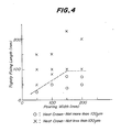
- a heat crown at the outer peripheral surface of the sleeve during the injection (expressed by difference in thermal expansion between the central portion and the portion located by 15 mm toward the central portion from the edge portion) was as small as 40 ⁇ m.
- the average thickness of the strip sheet was 21 ⁇ m with a longitudinal deviation of 1 ⁇ m and a thickness difference of as extremely small as 2 ⁇ m.
- an Fe-B-Si base amorphous alloy strip sheet was prepared in the same manner as in Example 1.
- a heat crown at the outer peripheral surface of the sleeve during the injection was as large as 350 ⁇ m.
- the thickness of the resulting strip sheet was 16 ⁇ m at the widthwise central portion, and 25 ⁇ m at the edge portion with thickness difference of as large as 9 ⁇ m. Further, numerous holes penetrating the widthwise center portion of the strip sheet over the entire thickness were formed.
- the deformation of the cooling roll in a barrel-like shape due to the heat crown during the production of the rapidly solidified metal strip sheets is solved by a completely novel method different from the conventional technique, that is, by releasing the thermal expansion of the sleeve in the roll axial direction while the axial end portions of the sleeve are substantially nonrestraint from the roll base body.
- the deviation in the thickness in the strip sheets can largely be reduced without necessitating complicated changes in the roll structure. Therefore, a huge interests can be obtained in the industrial field.
Landscapes
- Engineering & Computer Science (AREA)
- Mechanical Engineering (AREA)
- Continuous Casting (AREA)
- Rolls And Other Rotary Bodies (AREA)
Applications Claiming Priority (2)
| Application Number | Priority Date | Filing Date | Title |
|---|---|---|---|
| JP61208854A JPH0620614B2 (ja) | 1986-09-06 | 1986-09-06 | 急冷金属薄帯製造用の冷却ロ−ル |
| JP208854/86 | 1986-09-06 |
Publications (3)
| Publication Number | Publication Date |
|---|---|
| EP0260835A2 true EP0260835A2 (de) | 1988-03-23 |
| EP0260835A3 EP0260835A3 (en) | 1989-07-12 |
| EP0260835B1 EP0260835B1 (de) | 1992-12-23 |
Family
ID=16563213
Family Applications (1)
| Application Number | Title | Priority Date | Filing Date |
|---|---|---|---|
| EP87307596A Expired - Lifetime EP0260835B1 (de) | 1986-09-06 | 1987-08-27 | Kühlrollen zum Giessen von schnell erstarrenden Metallblechen |
Country Status (8)
| Country | Link |
|---|---|
| US (1) | US4809768A (de) |
| EP (1) | EP0260835B1 (de) |
| JP (1) | JPH0620614B2 (de) |
| KR (1) | KR910000127B1 (de) |
| CN (1) | CN1008701B (de) |
| AU (1) | AU581372B2 (de) |
| CA (1) | CA1307644C (de) |
| DE (1) | DE3783187T2 (de) |
Cited By (4)
| Publication number | Priority date | Publication date | Assignee | Title |
|---|---|---|---|---|
| FR2654372A1 (fr) * | 1989-11-16 | 1991-05-17 | Siderurgie Fse Inst Rech | Cylindre pour un dispositif de coulee continue sur un ou entre deux cylindres. |
| EP0471279A3 (en) * | 1990-08-17 | 1992-12-02 | Sundwiger Eisenhuette Maschinenfabrik Gmbh & Co. | Pouring wheel, especially for single roll casting machines |
| US8505611B2 (en) | 2011-06-10 | 2013-08-13 | Castrip, Llc | Twin roll continuous caster |
| US8607848B2 (en) | 2008-08-05 | 2013-12-17 | Nucor Corporation | Method for casting metal strip with dynamic crown control |
Families Citing this family (10)
| Publication number | Priority date | Publication date | Assignee | Title |
|---|---|---|---|---|
| AU708230B2 (en) * | 1996-02-16 | 1999-07-29 | Bhp Steel (Jla) Pty Limited | Roll cooling structure for twin roll continuous caster |
| AUPN811396A0 (en) * | 1996-02-16 | 1996-03-07 | Bhp Steel (Jla) Pty Limited | Roll cooling structure for twin roll continuous caster |
| US7862957B2 (en) * | 2003-03-18 | 2011-01-04 | Apple Inc. | Current collector plates of bulk-solidifying amorphous alloys |
| CN102886503B (zh) * | 2012-10-24 | 2014-11-26 | 青岛云路新能源科技有限公司 | 一种制作纳米晶的冷却辊装置 |
| CN103418765B (zh) * | 2013-08-28 | 2015-06-24 | 青岛云路新能源科技有限公司 | 一种防麻点非晶结晶器 |
| CN104439132A (zh) * | 2014-12-24 | 2015-03-25 | 江苏锴博材料科技有限公司 | 非晶制带生产用冷却辊 |
| DE102014226998A1 (de) * | 2014-12-29 | 2016-06-30 | Siemens Vai Metals Technologies Gmbh | Rolle für eine metallurgische Anlage |
| CN107350441B (zh) * | 2017-09-11 | 2023-03-17 | 安徽工业大学 | 一种柔性辊接触式薄带材冷却装置 |
| CN108759463A (zh) * | 2018-08-28 | 2018-11-06 | 方大特钢科技股份有限公司 | 轧钢加热炉悬臂辊辊套 |
| WO2022196672A1 (ja) * | 2021-03-17 | 2022-09-22 | Hilltop株式会社 | Fe-Si-B系厚板急冷凝固合金薄帯の製造方法 |
Family Cites Families (19)
| Publication number | Priority date | Publication date | Assignee | Title |
|---|---|---|---|---|
| DE1527650A1 (de) * | 1966-01-28 | 1970-03-19 | Willi Manthey | Tragrolle fuer Warmgut |
| FR2118332A5 (en) * | 1970-12-17 | 1972-07-28 | Electro Ceramique Cie Gl | Roller drive for ceramics kiln - comprising fluid cooled steel roller inside a refractory roller |
| US4565237A (en) * | 1979-08-17 | 1986-01-21 | Allied Corporation | Expandable quench surface |
| JPS5668559A (en) * | 1979-11-07 | 1981-06-09 | Hitachi Metals Ltd | Metal sheet manufacturing device |
| US4307771A (en) * | 1980-01-25 | 1981-12-29 | Allied Corporation | Forced-convection-cooled casting wheel |
| JPS56151149A (en) * | 1980-04-23 | 1981-11-24 | Kubota Ltd | Assembling type roll for continuous casting of slab |
| JPS57112954A (en) * | 1980-12-01 | 1982-07-14 | Hitachi Ltd | Producing device for alloy sheet |
| JPS57165355U (de) * | 1981-04-13 | 1982-10-18 | ||
| JPS5847541A (ja) * | 1981-09-16 | 1983-03-19 | Hitachi Ltd | 薄板製造装置 |
| AU560682B2 (en) * | 1982-07-13 | 1987-04-16 | Allied Corporation | Two piece chilled casting wheel |
| US4537239A (en) * | 1982-07-13 | 1985-08-27 | Allied Corporation | Two piece casting wheel |
| JPS5942160A (ja) * | 1982-09-02 | 1984-03-08 | Nippon Steel Corp | 非晶質合金薄帯製造用冷却ロ−ル |
| JPS5954445A (ja) * | 1982-09-24 | 1984-03-29 | Hitachi Ltd | 薄板金属製造装置の回転冷却ロ−ル |
| JPS6035221B2 (ja) * | 1982-10-12 | 1985-08-13 | 石川島播磨重工業株式会社 | 金属帯板連続鋳造方法及びその装置 |
| JPS59163057A (ja) * | 1983-03-07 | 1984-09-14 | Kawasaki Steel Corp | 急冷金属薄帯の製造方法および冷却ロ−ル |
| JPS59229263A (ja) * | 1983-06-13 | 1984-12-22 | Hitachi Ltd | アモルファス合金シート製造装置 |
| JPS61189854A (ja) * | 1985-02-19 | 1986-08-23 | Daido Steel Co Ltd | 水冷ロ−ル |
| JPH0633857A (ja) * | 1992-07-13 | 1994-02-08 | Mitsubishi Electric Corp | 内燃機関点火装置 |
| JPH06138745A (ja) * | 1992-10-26 | 1994-05-20 | Ricoh Co Ltd | カラー画像形成装置 |
-
1986
- 1986-09-06 JP JP61208854A patent/JPH0620614B2/ja not_active Expired - Lifetime
-
1987
- 1987-08-26 US US07/089,527 patent/US4809768A/en not_active Expired - Fee Related
- 1987-08-27 DE DE8787307596T patent/DE3783187T2/de not_active Expired - Fee Related
- 1987-08-27 EP EP87307596A patent/EP0260835B1/de not_active Expired - Lifetime
- 1987-09-03 CA CA000546063A patent/CA1307644C/en not_active Expired - Lifetime
- 1987-09-04 AU AU77993/87A patent/AU581372B2/en not_active Ceased
- 1987-09-05 KR KR1019870009831A patent/KR910000127B1/ko not_active Expired
- 1987-09-05 CN CN87106180A patent/CN1008701B/zh not_active Expired
Cited By (7)
| Publication number | Priority date | Publication date | Assignee | Title |
|---|---|---|---|---|
| FR2654372A1 (fr) * | 1989-11-16 | 1991-05-17 | Siderurgie Fse Inst Rech | Cylindre pour un dispositif de coulee continue sur un ou entre deux cylindres. |
| EP0428464A1 (de) * | 1989-11-16 | 1991-05-22 | USINOR SACILOR Société Anonyme | Zylinder für Einzel- oder Doppelrollenstranggiessvorrichtung |
| US5152333A (en) * | 1989-11-16 | 1992-10-06 | Usinor Sacilor | Roll for a device for continuous casting on a roll or between two rolls |
| TR25113A (tr) * | 1989-11-16 | 1992-11-01 | Usinor Sacilor | BIR SILINDIR üZERINDE VEYA IKI SILINDIR ARASINDA DEVAMLI DÖKüM YAPMAK üZERE BIR CIHAZ ICIN SILINDIR |
| EP0471279A3 (en) * | 1990-08-17 | 1992-12-02 | Sundwiger Eisenhuette Maschinenfabrik Gmbh & Co. | Pouring wheel, especially for single roll casting machines |
| US8607848B2 (en) | 2008-08-05 | 2013-12-17 | Nucor Corporation | Method for casting metal strip with dynamic crown control |
| US8505611B2 (en) | 2011-06-10 | 2013-08-13 | Castrip, Llc | Twin roll continuous caster |
Also Published As
| Publication number | Publication date |
|---|---|
| CA1307644C (en) | 1992-09-22 |
| KR880003679A (ko) | 1988-05-28 |
| KR910000127B1 (ko) | 1991-01-21 |
| CN87106180A (zh) | 1988-05-11 |
| US4809768A (en) | 1989-03-07 |
| DE3783187D1 (de) | 1993-02-04 |
| CN1008701B (zh) | 1990-07-11 |
| JPH0620614B2 (ja) | 1994-03-23 |
| EP0260835A3 (en) | 1989-07-12 |
| EP0260835B1 (de) | 1992-12-23 |
| AU581372B2 (en) | 1989-02-16 |
| JPS6368250A (ja) | 1988-03-28 |
| AU7799387A (en) | 1988-03-10 |
| DE3783187T2 (de) | 1993-05-06 |
Similar Documents
| Publication | Publication Date | Title |
|---|---|---|
| US4809768A (en) | Cooling rolls for producing rapidly solidified metal strip sheets | |
| EP0212423B1 (de) | Stranggussvorrichtung vom Zwillingsrollentyp | |
| US4911226A (en) | Method and apparatus for continuously casting strip steel | |
| AU2004278056A1 (en) | Belt casting of non-ferrous and light metals and apparatus therefor | |
| US4252178A (en) | Continuous casting mold with resiliently held graphite liner members | |
| KR930011960B1 (ko) | 연속주조에서 주조 스테인레스강 스트립을 폭방향으로 균일하게 급속냉각하는 방법 | |
| EP0440650B1 (de) | Herstellung dünner metallbrammen | |
| US4287934A (en) | Continuous casting mold | |
| JPS626897B2 (de) | ||
| JPS6277152A (ja) | 双ロ−ルを使用した薄板連続鋳造方法及び装置 | |
| JPS63252649A (ja) | 薄鋳片連続鋳造機 | |
| EP0780176A2 (de) | Vorrichtung und Verfahren zum Stranggiessen | |
| JP2005088063A (ja) | ストリップキャスター用冷却ロール | |
| JPH01284463A (ja) | 薄鋳片連続鋳造機の短辺側板 | |
| JP3314036B2 (ja) | 連続鋳造方法および連続鋳造装置 | |
| KR0135343B1 (ko) | 강의 소단면 빌레트 연속주조시 주형 냉각방법 | |
| JPS5838640A (ja) | 薄板の連続鋳造装置 | |
| US4545424A (en) | Method of continuously casting steel | |
| KR100406376B1 (ko) | 쌍롤식 박판주조법에서의 균일한 주편의 제조방법 | |
| JP2000000640A (ja) | 双ロール式連続鋳造装置 | |
| JPS61108454A (ja) | 冷却ロ−ル | |
| KR100333069B1 (ko) | 쌍롤식박판주조장치에서의주편균일냉각방법 | |
| JPH11156492A (ja) | 薄板連続鋳造用ロール | |
| JP7460897B2 (ja) | 双ロール式連続鋳造装置および双ロール式連続鋳造方法 | |
| JPH0677790B2 (ja) | 金属を連続的に鋳造する方法及び装置 |
Legal Events
| Date | Code | Title | Description |
|---|---|---|---|
| PUAI | Public reference made under article 153(3) epc to a published international application that has entered the european phase |
Free format text: ORIGINAL CODE: 0009012 |
|
| AK | Designated contracting states |
Kind code of ref document: A2 Designated state(s): BE DE FR GB NL SE |
|
| PUAL | Search report despatched |
Free format text: ORIGINAL CODE: 0009013 |
|
| AK | Designated contracting states |
Kind code of ref document: A3 Designated state(s): BE DE FR GB NL SE |
|
| 17P | Request for examination filed |
Effective date: 19890915 |
|
| 17Q | First examination report despatched |
Effective date: 19910807 |
|
| GRAA | (expected) grant |
Free format text: ORIGINAL CODE: 0009210 |
|
| AK | Designated contracting states |
Kind code of ref document: B1 Designated state(s): BE DE FR GB NL SE |
|
| PG25 | Lapsed in a contracting state [announced via postgrant information from national office to epo] |
Ref country code: SE Effective date: 19921223 Ref country code: NL Effective date: 19921223 Ref country code: BE Effective date: 19921223 |
|
| ET | Fr: translation filed | ||
| REF | Corresponds to: |
Ref document number: 3783187 Country of ref document: DE Date of ref document: 19930204 |
|
| NLV1 | Nl: lapsed or annulled due to failure to fulfill the requirements of art. 29p and 29m of the patents act | ||
| PLBE | No opposition filed within time limit |
Free format text: ORIGINAL CODE: 0009261 |
|
| STAA | Information on the status of an ep patent application or granted ep patent |
Free format text: STATUS: NO OPPOSITION FILED WITHIN TIME LIMIT |
|
| 26N | No opposition filed | ||
| PGFP | Annual fee paid to national office [announced via postgrant information from national office to epo] |
Ref country code: FR Payment date: 19980814 Year of fee payment: 12 |
|
| PGFP | Annual fee paid to national office [announced via postgrant information from national office to epo] |
Ref country code: GB Payment date: 19980818 Year of fee payment: 12 |
|
| PGFP | Annual fee paid to national office [announced via postgrant information from national office to epo] |
Ref country code: DE Payment date: 19980907 Year of fee payment: 12 |
|
| PG25 | Lapsed in a contracting state [announced via postgrant information from national office to epo] |
Ref country code: GB Free format text: LAPSE BECAUSE OF NON-PAYMENT OF DUE FEES Effective date: 19990827 |
|
| GBPC | Gb: european patent ceased through non-payment of renewal fee |
Effective date: 19990827 |
|
| PG25 | Lapsed in a contracting state [announced via postgrant information from national office to epo] |
Ref country code: FR Free format text: LAPSE BECAUSE OF NON-PAYMENT OF DUE FEES Effective date: 20000428 |
|
| PG25 | Lapsed in a contracting state [announced via postgrant information from national office to epo] |
Ref country code: DE Free format text: LAPSE BECAUSE OF NON-PAYMENT OF DUE FEES Effective date: 20000601 |
|
| REG | Reference to a national code |
Ref country code: FR Ref legal event code: ST |