EP0260940A2 - Beglaubigungsechtheitsprüfung und Identifizierung von Dokumenten oder anderen Gegenständen - Google Patents
Beglaubigungsechtheitsprüfung und Identifizierung von Dokumenten oder anderen Gegenständen Download PDFInfo
- Publication number
- EP0260940A2 EP0260940A2 EP87308178A EP87308178A EP0260940A2 EP 0260940 A2 EP0260940 A2 EP 0260940A2 EP 87308178 A EP87308178 A EP 87308178A EP 87308178 A EP87308178 A EP 87308178A EP 0260940 A2 EP0260940 A2 EP 0260940A2
- Authority
- EP
- European Patent Office
- Prior art keywords
- magnetic
- characteristic
- layer
- document
- magnetic material
- Prior art date
- Legal status (The legal status is an assumption and is not a legal conclusion. Google has not performed a legal analysis and makes no representation as to the accuracy of the status listed.)
- Granted
Links
- 238000012795 verification Methods 0.000 title claims description 12
- 239000000696 magnetic material Substances 0.000 claims abstract description 42
- 239000000463 material Substances 0.000 claims abstract description 8
- 239000006249 magnetic particle Substances 0.000 claims abstract description 7
- 230000001419 dependent effect Effects 0.000 claims abstract 2
- 238000000034 method Methods 0.000 claims description 46
- 239000000758 substrate Substances 0.000 claims description 27
- 230000008569 process Effects 0.000 claims description 24
- 238000004519 manufacturing process Methods 0.000 claims description 5
- 239000006185 dispersion Substances 0.000 claims description 4
- 230000001788 irregular Effects 0.000 claims description 3
- 238000004026 adhesive bonding Methods 0.000 claims description 2
- 238000012546 transfer Methods 0.000 claims description 2
- 238000000576 coating method Methods 0.000 abstract description 3
- 239000011248 coating agent Substances 0.000 abstract description 2
- 239000004922 lacquer Substances 0.000 abstract description 2
- 230000007723 transport mechanism Effects 0.000 description 10
- 238000012545 processing Methods 0.000 description 7
- 230000002463 transducing effect Effects 0.000 description 7
- 230000005415 magnetization Effects 0.000 description 6
- 230000007246 mechanism Effects 0.000 description 5
- 230000008859 change Effects 0.000 description 4
- 238000010586 diagram Methods 0.000 description 4
- 230000004907 flux Effects 0.000 description 4
- 238000000151 deposition Methods 0.000 description 3
- 230000003287 optical effect Effects 0.000 description 3
- 238000005070 sampling Methods 0.000 description 3
- 230000008901 benefit Effects 0.000 description 2
- 230000003111 delayed effect Effects 0.000 description 2
- 230000004048 modification Effects 0.000 description 2
- 238000012986 modification Methods 0.000 description 2
- 230000003466 anti-cipated effect Effects 0.000 description 1
- 238000013459 approach Methods 0.000 description 1
- 230000003750 conditioning effect Effects 0.000 description 1
- 238000012790 confirmation Methods 0.000 description 1
- 125000004122 cyclic group Chemical group 0.000 description 1
- 230000005347 demagnetization Effects 0.000 description 1
- 210000003298 dental enamel Anatomy 0.000 description 1
- 238000005137 deposition process Methods 0.000 description 1
- 238000011161 development Methods 0.000 description 1
- 230000002349 favourable effect Effects 0.000 description 1
- 239000000835 fiber Substances 0.000 description 1
- 230000005381 magnetic domain Effects 0.000 description 1
- 239000000203 mixture Substances 0.000 description 1
- 239000002245 particle Substances 0.000 description 1
- 239000011253 protective coating Substances 0.000 description 1
- 230000009467 reduction Effects 0.000 description 1
- 230000001953 sensory effect Effects 0.000 description 1
- 239000000126 substance Substances 0.000 description 1
- 238000012360 testing method Methods 0.000 description 1
- 230000032258 transport Effects 0.000 description 1
Images


Classifications
-
- G—PHYSICS
- G07—CHECKING-DEVICES
- G07F—COIN-FREED OR LIKE APPARATUS
- G07F7/00—Mechanisms actuated by objects other than coins to free or to actuate vending, hiring, coin or paper currency dispensing or refunding apparatus
- G07F7/08—Mechanisms actuated by objects other than coins to free or to actuate vending, hiring, coin or paper currency dispensing or refunding apparatus by coded identity card or credit card or other personal identification means
- G07F7/086—Mechanisms actuated by objects other than coins to free or to actuate vending, hiring, coin or paper currency dispensing or refunding apparatus by coded identity card or credit card or other personal identification means by passive credit-cards adapted therefor, e.g. constructive particularities to avoid counterfeiting, e.g. by inclusion of a physical or chemical security-layer
-
- G—PHYSICS
- G07—CHECKING-DEVICES
- G07D—HANDLING OF COINS OR VALUABLE PAPERS, e.g. TESTING, SORTING BY DENOMINATIONS, COUNTING, DISPENSING, CHANGING OR DEPOSITING
- G07D7/00—Testing specially adapted to determine the identity or genuineness of valuable papers or for segregating those which are unacceptable, e.g. banknotes that are alien to a currency
- G07D7/004—Testing specially adapted to determine the identity or genuineness of valuable papers or for segregating those which are unacceptable, e.g. banknotes that are alien to a currency using digital security elements, e.g. information coded on a magnetic thread or strip
-
- G—PHYSICS
- G07—CHECKING-DEVICES
- G07D—HANDLING OF COINS OR VALUABLE PAPERS, e.g. TESTING, SORTING BY DENOMINATIONS, COUNTING, DISPENSING, CHANGING OR DEPOSITING
- G07D7/00—Testing specially adapted to determine the identity or genuineness of valuable papers or for segregating those which are unacceptable, e.g. banknotes that are alien to a currency
- G07D7/004—Testing specially adapted to determine the identity or genuineness of valuable papers or for segregating those which are unacceptable, e.g. banknotes that are alien to a currency using digital security elements, e.g. information coded on a magnetic thread or strip
- G07D7/0047—Testing specially adapted to determine the identity or genuineness of valuable papers or for segregating those which are unacceptable, e.g. banknotes that are alien to a currency using digital security elements, e.g. information coded on a magnetic thread or strip using checkcodes, e.g. coded numbers derived from serial number and denomination
-
- G—PHYSICS
- G07—CHECKING-DEVICES
- G07D—HANDLING OF COINS OR VALUABLE PAPERS, e.g. TESTING, SORTING BY DENOMINATIONS, COUNTING, DISPENSING, CHANGING OR DEPOSITING
- G07D7/00—Testing specially adapted to determine the identity or genuineness of valuable papers or for segregating those which are unacceptable, e.g. banknotes that are alien to a currency
- G07D7/04—Testing magnetic properties of the materials thereof, e.g. by detection of magnetic imprint
-
- G—PHYSICS
- G07—CHECKING-DEVICES
- G07D—HANDLING OF COINS OR VALUABLE PAPERS, e.g. TESTING, SORTING BY DENOMINATIONS, COUNTING, DISPENSING, CHANGING OR DEPOSITING
- G07D7/00—Testing specially adapted to determine the identity or genuineness of valuable papers or for segregating those which are unacceptable, e.g. banknotes that are alien to a currency
- G07D7/20—Testing patterns thereon
Definitions
- This invention relates to authenticity-verification and identification of documents or other objects, and to such documents or other objects, of the kind in which a characteristic of the object is sensed for use in the verification or identification process.
- a document or other object which has a verifiable authenticity and in which a base member provides a support substrate is characterised in that a body of magnetic material carried by the support substrate possesses a repeatably sensible, random characteristic, and that the base member bears a machine-readable record indicative of the repeatably sensible characteristic.
- Such a document or other object may be produced using a process according to another aspect of the present invention, which is characterised in that the body of magnetic material is formed on the substrate to have a random magnetic characteristic, that the magnetic characteristic is sensed, and that representations of the sensed characteristic are recorded on the object for subsequent verification of authenticity of that object.
- the document or other object may be identified or have its authenticity verified by a method characterised in that the magnetic characteristic is freshly sensed to provide fresh representations thereof, and that these fresh representations are compared with representations of the characteristic recorded on the object.
- Magnetic material has advantage in that it is generally inexpensive and relatively immune from dirt and small scratches.
- the present invention is based on recognizing certain random characteristics of magnetic media and utilizing such characteristics as a basis for identification.
- Magnetic materials may, for example, be readily printed or otherwise disposed on a base member (for example, paper or other fibre-composed medium) to impart random magnetic characteristics that may be repeatably sensed for identification purposes.
- a technique for identification purposes involving magnetic material is known from U.S. Patent Specification No 4,114,032 (Brosow et al), where the sensible characteristic is provided by magnetizable elements in the form of fibres, embedded in a document.
- the present invention has broader aspect than that, and may be implemented, for example, through printing or otherwise depositing a layer of magnetic material on a paper (or other fibre-composed) substrate, magnetic variations or irregularities to manifest the repeatably sensible characteristic arising out of nonuniformity of the paper surface, nonuniformities in the printing or other deposition process, and/or magnetic-particle dispersion in the magnetic material.
- Magnetic-density variations are randomly created to characterise the document or other object uniquely, and a record of this may be provided on the object in a magnetic stripe or in any other machine-readable form (for example, as optically-readable codes).
- a document or other object may be identified or verified in authenticity by freshly sensing the random magnetic characteristic, reducing it to a data format consistent with that used for the recording, and comparing the result with the recorded data.
- the present invention may be implemented in various ways, using different forms of magnetic materials and media, different support materials and different production and utiIization techniques.
- the random magnetic characteristic may be accomplished by printing a document with varying magnetic materials.
- various techniques may be employed to sense the layer or other body of magnetic material, and to precondition such layer or body prior to sensing.
- a document 10 symbolized as a stock certificate, is illustrated embodying the present invention. Specifically, in addition to considerable printed indicia 12, the document 10 carries a conventional magnetic recording stripe 14 and a magnetic characteristic layer 16 also in the configuration of a narrow strip.
- the layer 16 has a magnetic characteristic as described in detail below, which can be sensed and reduced to a convenient data format to identify the document 10. Specifically, as illustrated in FIGURE 1, the magnetic characteristic of the layer 16 is sensed and reduced to a digital format which is recorded on the magnetic stripe 14. Accordingly, the document 10 can be effectively authenticated by freshly sensing the magnetic characteristic of the layer 16, processing the sensed signal according to a predetermined format, and comparing the result with data from the magnetic stripe 14.
- a variety of correlation and signal processing techniques may be employed along with a variety of sensing techniques; however in any event, a favorable comparison verifies the authenticity of the document 10.
- the magnetic data stripe 14 involves techniques of the magnetic recording industry wherein the media of the magnetic stripe is an integral part of a magnetic read-write system. Accordingly, the media of the magnetic stripe 14 is tightly specified and highly controlled in accordance with well known standards of the art. Conversely, the media of the layer 16 varies significantly and in fact it is such variation that affords the characteristic for identifying the document 10.
- the density along the magnetic layer 16 varies for three primary reasons, i.e. the nonuniformity of the paper in the document 10, the process of depositing the layer 16 on the document 10 and the dispersion of magnetic particles in the layer 16.
- the density variations are randomly created such as to afford uniqueness to the document, and are fixed and repeatably sensible to enable their use in identification of the document.
- density and remanent magnetization are equivalents.
- the remanent magnetization may vary in a fixed, repeatable pattern for a given magnetic layer while the density remains relatively constant.
- Such a fixed, repeatable pattern is a form of the characteristic as described and utilized by the present invention for object identification.
- noise results when a magnetic media has been magnetized by a DC field.
- Modulation noise is defined as variations in the reproduced amplitude which occur when an AC signal of constant amplitude is recorded.
- Bias noise occurs when an AC bias is applied to a recording head with substantially no signal current, e.g. no signal riding on the AC bias.
- Bulk-erased noise results when a media has been demagnetized by a cyclic field. Note that bulk-erased noise occurs because a media is composed of numerous magnetic domains which always remain magnetized. That is, only the polarity changes.
- Demagnetization on a large scale causes substantially equal numbers of particles to be magnetized in opposing directions with a net difference of substantially zero. Accordingly, in a perfectly dispersed media (magnetic particles equal) that is magnetized longitudinally in a perfectly uniform manner, flux emanates only at the ends. As a result, the noise would be the same as if the media was in a state of zero net magnetic flux. Any change will cause flux, that is, variance from the state of zero net magnetic flux is caused by nonuniformity.
- nonuniformity of magnetization can be attributed to three major causes, specifically: (1) variation in the amount of magnetic material per unit of volume along the media (produced by the printing process or nonuniformities in the substrate surface as paper); (2) variations in the magnetic material; and (3) fluctuations in the applied recording current.
- each of the sources of nonuniformity will be considered independently as related to the present development. However, preliminarily reference will be made to the enlarged sectional view of FIGURE 2 illustrating nonlinearities of the magnetic layer 16. Specifically, the layer 16 is deposited on a sheet 18 providing a support substrate.
- the sheet 18 may comprise a multitude of different papers or paper-like materials as a product comprising a collection of plastic fibers known as "Premoid".
- the sheet 18 has a surface 20 indicated as an irregular boundary which receives and supports the magnetic layer 16 and a protective coating 17.
- the irregularity of the surface 20 along with irregularities in the surface 22 of the layer 16 are illustrated in FIGURE 2 and constitute a source of nonuniformity, i.e. variation in the amount of magnetic material per unit of volume along the media.
- the nonuniformity affords a characteristic that is enhanced by the layer 17 of lacquer, enamel or other nonmagnetic coating that may vary the spacing of a sensor head from the layer 16.
- FIGURE 3 The nonlinearity is illustrated graphically in FIGURE 3. Specifically, an idealized section of the support substrate 24 is illustrated carrying a similarly represented section 26 of magnetic media. That is, the solid lines depict perfect dispersion of magnetic material 26 on a perfect substrate 24.
- the dashed lines 28 and 30 illustrate variations from the idealized structure which result from printing process variations (asperity) and substrate variations (nonuniformity). That is, the asperity or roughness indicated by the dashed line 28 is attributed to the printing process for depositing the section 26. Variations in the substrate illustrated by the dashed line 30 are caused by variations at the surface of the substrate 24, e.g. the paper.
- FIGURE 3 provide the basis for individual characteristics which enable identifying objects in accordance herewith. That is, variations in the magnetic material thickness as illustrated in FIGURES 2 and 3 afford a characteristic that can be repeatedly measured for identifying an object.
- the irregularities illustrated by the line 28 may change as the surface defined by the line 28 is abraded as with use of the document.
- the variations represented by the line 30 are less susceptible to change.
- magnetic character also may result from varying the magnetic material in the layer 16 (FIGURE 1).
- character may be obtained by using an ink mixture to print the layer 16 which carries magnetic particles of varying size, or like magnetic particles that are variably dispersed.
- Such a technique may be employed to provide the magnetic character or to enhance the character of a magnetic layer. Similar structures can be accomplished by heat transfer, slurrying or gluing.
- character may be sensed as a result of variations in the recording current.
- variations are accounted for in implementations of the present invention by subjecting the magnetic layer to a standardized treatment, e.g. erasing and recording to a standard.
- a substrate is selected, cut to the desired document size and printed with the layer 16 as illustrated in FIGURE 1.
- the printed indicia 12 may also be deposited.
- the magnetic stripe 14 may be adhesively affixed. Such a "raw" document form is then processed to accomplish the document 10 in accordance herewith. Such processing involves apparatus as represented in FIGURE 4 and will now be considered in detail.
- a raw form of the document 10 is received by a transport mechanism 32 (FIGURE 4, right central) the physical relationship being symbolically represented by a dashed line 34.
- a transport mechanism 32 (FIGURE 4, right central) the physical relationship being symbolically represented by a dashed line 34.
- a wide variety of transport mechanisms for dynamic magnetic recording are well known in the prior art and may be implemented for use as the mechanism 32 for processing the document 10. Essentially, such mechanisms detect the presence of a document then move the document or other sheet form to facilitate dynamic sensing and recording. As represented in FIGURE 4, the mechanism 32 moves the document 10 to the right as represented by an arrow (upper right).
- a magnetic record head 36 (right) is supported in transducing relationship with the magstripe 14.
- the head 36 receives recording signals from a data compiler 38 which is connected to receive signals from a data source 40 and a signal processor 42.
- the signal processor 42 receives signals from a sense head 44 disposed at the left as illustrated, in transducing relationship with the layer 16. Essentially, the head 44 senses the characteristic of the layer 16 in the form of an electrical signal which is applied to processor 42 to provide a digital format that is combined with other digital data from the source 40 by the compiler 38 and recorded on the magstripe 14.
- the transport mechanism 32 transports the document 10 from left to right as depicted. Consequently, the head 44 substantially completes a scansion of the document 10 before the head 36 begins to scan the document 10.
- the head 44 reads the characteristic from the layer 16 and thereafter the head 36 records signals representative of the characteristic in the stripe 14.
- Preceding the head 44 are conditioning heads, specifically an erase head 46 and a record head 48.
- the erase head 46 is driven by an erase circuit 50 and the record head 48 is driven by a record circuit 52.
- the layer 16 is erased or cleared of spurious magnetic content.
- the layer 16 next passes under the head 48 which is driven by a circuit 52 to accomplish a standard recording on the layer 16.
- the head might be driven with a linear DC signal to accomplish DC noise, by a linear AC signal to accomplish modulation noise or by a linear bias signal to accomplish bias noise.
- a nonlinear recording also might be employed. In any event, a standard record is thus accomplished.
- the layer 16 next encounters the head 44 which senses the magnetic characteristic of the preconditioned layer 16. Consequently, an analog signal manifesting the characteristic is supplied from the head 44 to the characteristic signal processor 42. A portion or portions of the analog signal may be selected to manifest select areas of the layer 16 as by well known sampling techniques and apparatus in the processor 42 to provide specific values for reduction to digital representations. Note that techniques for selecting and processing area representative analog signals are disclosed in the above-referenced United States Patent to Goldman, 4,423,415.
- the processor 42 also incorporates an analog-digital converter as well known in the art for converting the selected analog samples. Accordingly, a format of select digital signals representative of the magnetic characteristic are supplied from the processor 42 to the compiler 38.
- the compiler 38 also receives other data which may be representative of information concerning the document 10 and the techniques employed for sensing the characteristic of the layer 16.
- the data specifies the location of the characteristic features of concern.
- Such data is instrumental in selectively sampling the analog signal representative of the characteristic to obtain the specified signals to be digitized.
- the compiler 38 assembles the digital data and accordingly drives the record head 36 to accomplish the desired record in the magnetic stripe 14. With the completion of such recording, the document 10 is complete and may be subsequently processed for verification as genuine.
- Documents produced in accordance herewith may be subject to a wide variety of different applications and uses.
- the document 10 may be released to the owner and with reasonable safety may be placed in the hands of a bailee, for example as a pledge.
- a bailee for example as a pledge.
- the system of the present invention contemplates such verification and confirmation of the document 10 as genuine.
- a system of verification is illustrated in FIGURE 5 and will now be considered in detail.
- the system of FIGURE 5 receives the document 10 in a transport mechanism 60 somewhat as the mechanism described above with reference to FIGURE 4.
- the mechanism 60 is physically associated with a set of transducer heads in an arrangement distinctly different from that described above with respect to FIGURE 4.
- initial transducing relationship is established between the magnetic stripe 14 and a sensing head 62.
- the transport mechanism 60 senses the presence of the document 10 and supplies a signal. In the system of FIGURE 5 that signal is manifest in a line 64.
- the layer 16 encounters a sequence of heads 66, 68 and 70. Accordingly, the magnetic stripe 14 is sensed by the head 62 well ahead of the heads 66, 68 and 70 sensing the layer 16.
- the head 62 supplies digital data to a decoding circuit 72 which is in turn connected to a register 74. Accordingly, the magstripe 14 is sensed, the contents is decoded and set in the register 74. Specifically, the decoded data specifies the characteristic data of interest, the location of that data and any desired ancillary information, all in a digital format.
- the head 66 is connected to an erase circuit 76 while the record head 68 is connected to a record circuit 68. Accordingly, the heads 66 and 68 precondition the layer 16. The preconditioned layer 16 is then sensed by the sense head 70, connected to a characteristic signal processor 80. Note that the function of the heads 66, 68 and 70 is similar to that of the heads 44, 46 and 48 as described with respect to FIGURE 4. That is, the head 66 clears the layer 16, the head 68 imposes a predetermined recording pattern and the head 70 senses the layer to provide the characteristic signal as described in detail above. The resulting characteristic signal is supplied to a processor 80.
- the data decoding circuit 72 (upper left) supplies information to the processor 80 to specify the selection or sampling of values in the characteristic signal. That is, the characteristic signal processor 80 samples the same predetermined portions of the received signal to derive sets of digital values for comparison and may be as described in the above-referenced United States Patent 4,423,415.
- the sampled values are digitized then supplied from the processor 80 to a correlation circuit 82 which is also coupled to the register 74. Functionally, if appropriate, the correlation circuit 82 actuates an output device 84 to manifest predetermined degrees of similarity between the freshly observed characteristic data and the previously recorded characteristic data from the same locations.
- the correlation circuit 82 may take various well known forms. Peak values exceeding a threshold can be tested, various sampled values can be used or correlation algorithms may be implemented. Various forms of signal devices might be employed in the output device 84 as well known in the prior art.
- the transport mechanism 60 senses the presence of the document 10 and provides a signal through the line 64 to initiate the operation of the processor 80 and the circuit 72 to perform transducing operations.
- the signal indicating the presence of a document may be provided by an optical sensor in accordance with well known and widely used techniques of magnetic stripe card readers.
- the initial transducing relationship occurs when the magstripe 14 of the document 10 encounters the head 62.
- digital values representative of the document characteristic (layer 16) are sensed from the stripe 14 along with certain information to indicate the specific location of values for comparison within the layer 16.
- Other data may also be provided.
- the data relating to identification of the characteristic is supplied to the processor 80 while signals representative of the actual select characteristic are set in the register 74.
- the layer 16 encounters the heads 66, 68 and 70 in that sequence.
- the head 66 clears the layer of any spurious signals after which the head 68 records the layer with a predetermined test signal.
- the head 70 senses the recorded signal (along with other noise) for processing by the processor 80 to develop the select characteristic values in a digital format.
- the select characteristic values are supplied to the correlation circuit 82 which also receives previously sensed similar-format values from the register 74. Accordingly, the correlation circuit 82 determines the degree of correlation and in accordance with predetermined standards actuates the output device 84 accordingly. Thus, depending on the degree of correlation or similarity between the fresh characteristic values and the previously recorded characteristic values, the document 10 is authenticated as genuine.
- the use of a magnetic layer to provide an identifying characteristic affords different possibilities which account for random characteristics in a magnetic medium.
- the characteristic might result from variations in the gross amount of magnetic material, variations in the individual quantity of magnetic material or variations in the recording signal. Any of such variations might be sensed, refined and converted to a digital format using signal processing circuits as well known in the prior art.
- signal selectivity may be exercised in the interests of the nature of the document 10 or its intended use.
- the character resulting from variations in the gross amount of magnetic material per unit of volume along the layer 16 are attributed both to the printing process and nonuniformities of the substrate surface, see FIGURES 2 and 3.
- the character relating to irregularities indicated by the dashed line 28 may change somewhat with use of the document 10 in which the surface of the layer 16 is abraded.
- a magnetic characteristic may be sensed by providing a recording current in the magnetic record head to a level so that the effective recording field is nearly uniform throughout the magnetic material depth.
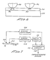
- the idealized substrate section 24 and the magnetic section 26 are illustrated in relation to a magnetic recording head 88.
- a dashed line 90 indicates an effective recording field that approaches uniformity through the depth of the section 26.
- a sensing of the section 26 that has reached maximum remanent magnetization yields a waveform that is directly related to the amount of magnetic material along the substrate which is fixed and repeatable relative to specific locations along the magnetic layer.
- Such a waveform represents a raw form of an observed characteristic.
- wear of the magnetic layer 16 (FIGURE 1) will not be expected to be negligible and as a result, compensation may be provided.
- a select magnetic characteristic is obtained by deriving the waveform described above along with another waveform that indicates the asperity variations as illustrated with respect to a head 92.
- the dashed line 94 involves a magnetic field which is limited to a space near the surface of the section 26.
- the head 92 senses the surface (asperity)
- the head 88 senses the total substrate section 26. Accordingly, the heads sense at different depths and a characteristic that is somewhat immune from surface wear in the magnetic layer may involve the subtractive combination of a deep field minus a shallow field. As a result, the asperity signal is eliminated from the total sensed signal. Essentially, the asperity waveform is the component which is susceptible to modification with wear of the document.
- the asperity waveform may be derived by passing a DC current through the recording head adjusted to produce minimum noise.
- the effective field penetrates to a level above the substrate nonuniformities. For example, a remanent magnetization of fifty percent of the maximum remanent magnetization accomplishes such an operation.
- a read-back of the magnetic stripe then generates the asperity waveform.
- FIGURE 7 a magnetic layer 16 is illustrated in FIGURE 7 which is being sensed by heads 102 and 104 similar to the heads 88 and 92 of FIGURE 6.
- the characteristic signals from the heads 102 and 104 are processed respectively by the processors 106 and 108.
- the signal from the processor 108 is delayed by a delay circuit 110 to be in space-time coincidence with the signal from the processor 106.
- the delayed signal from the circuit 110, and with the signal from the processor 106 are applied to a difference circuit 112 which essentially subtracts the asperity waveform from the total characteristic waveform.
- a characteristic analog signal is provided at an output 114 which is somewhat immune to changes in the surface of the magnetic layer 16.
- the structure of FIGURE 7 may replace either of the single heads 46 or 70 to provide a select characteristic somewhat immune to surface variations of the characteristic magnetic layer.
Landscapes
- Physics & Mathematics (AREA)
- General Physics & Mathematics (AREA)
- Engineering & Computer Science (AREA)
- Computer Security & Cryptography (AREA)
- Recording Or Reproducing By Magnetic Means (AREA)
- Magnetic Record Carriers (AREA)
- Credit Cards Or The Like (AREA)
- Paints Or Removers (AREA)
- Inspection Of Paper Currency And Valuable Securities (AREA)
Applications Claiming Priority (2)
| Application Number | Priority Date | Filing Date | Title |
|---|---|---|---|
| US909145 | 1986-09-19 | ||
| US06/909,145 US4806740A (en) | 1986-09-19 | 1986-09-19 | Magnetic characteristic identification system |
Publications (3)
| Publication Number | Publication Date |
|---|---|
| EP0260940A2 true EP0260940A2 (de) | 1988-03-23 |
| EP0260940A3 EP0260940A3 (en) | 1989-11-23 |
| EP0260940B1 EP0260940B1 (de) | 1996-02-07 |
Family
ID=25426700
Family Applications (1)
| Application Number | Title | Priority Date | Filing Date |
|---|---|---|---|
| EP87308178A Expired - Lifetime EP0260940B1 (de) | 1986-09-19 | 1987-09-16 | Beglaubigungsechtheitsprüfung und Identifizierung von Dokumenten oder anderen Gegenständen |
Country Status (5)
| Country | Link |
|---|---|
| US (1) | US4806740A (de) |
| EP (1) | EP0260940B1 (de) |
| JP (1) | JPS63129520A (de) |
| CA (1) | CA1291564C (de) |
| DE (1) | DE3751697T2 (de) |
Cited By (9)
| Publication number | Priority date | Publication date | Assignee | Title |
|---|---|---|---|---|
| EP0416826A1 (de) * | 1989-09-01 | 1991-03-13 | Toyo Ink Manufacturing Co., Ltd. | Methode der Identifizierung einer Information und Informationsträger zur Verwendung mit dieser Methode |
| FR2657981A1 (fr) * | 1990-02-05 | 1991-08-09 | Kodak Pathe | Procede de certification d'un support d'informations et support obtenu selon le procede. |
| AU631095B2 (en) * | 1990-01-10 | 1992-11-12 | Brandt Inc. | Magnetic document validator employing remanence and saturation measurements |
| EP0570162A3 (de) * | 1992-05-11 | 1994-03-23 | Canon Kk | |
| WO1994001837A3 (en) * | 1992-07-14 | 1994-06-09 | Technitrol Inc | Document counting and batching apparatus with counterfeit detection |
| WO1996002901A1 (en) * | 1994-07-15 | 1996-02-01 | Thorn Secure Science Limited | Authentication technique |
| EP0589195A3 (en) * | 1992-09-25 | 1996-03-06 | Nhk Spring Co Ltd | A method and an apparatus for checking objects to be checked for authenticity |
| WO1997024699A1 (en) * | 1995-12-29 | 1997-07-10 | S. E. Axis Limited | Authentication of articles |
| FR2765014A1 (fr) * | 1997-06-24 | 1998-12-24 | Rene Boulnois | Procede d'authentification d'un document en papier, document de securite en papier, et dispositif de controle de l'authenticite de documents en papier |
Families Citing this family (71)
| Publication number | Priority date | Publication date | Assignee | Title |
|---|---|---|---|---|
| US4929821A (en) * | 1986-03-12 | 1990-05-29 | Skidata Computer G.m.b.H. | Method of forgery-protecting a data carrier, a forgery-protected data carrier and apparatuses for handling, processing and monitoring the data carrier |
| US4985614A (en) * | 1987-01-16 | 1991-01-15 | Rand Mcnally & Company | Object verification apparatus and method |
| US4906988A (en) * | 1987-01-27 | 1990-03-06 | Rand Mcnally & Co. | Object verification system and method |
| FR2616943B1 (fr) * | 1987-06-18 | 1990-11-23 | Bonnaval Lamothe Michel | Procede de controle simultane de l'authenticite d'un support d'information et de la non-falsification de ladite information et dispositifs pour sa mise en oeuvre |
| US4937995A (en) * | 1988-06-16 | 1990-07-03 | Carlisle Corporation | Noninvasively identifiable membrane roof system |
| US5216229A (en) * | 1989-06-05 | 1993-06-01 | Rand Mcnally & Company | Verifiable object having incremental key |
| JPH03282690A (ja) * | 1990-03-29 | 1991-12-12 | Omron Corp | カードセキュリティシステム |
| US5177344A (en) * | 1990-10-05 | 1993-01-05 | Rand Mcnally & Company | Method and appparatus for enhancing a randomly varying security characteristic |
| US5206814A (en) * | 1990-10-09 | 1993-04-27 | Robot Aided Manufacturing Center, Inc. | Robotic music store |
| JPH0696294A (ja) * | 1992-09-10 | 1994-04-08 | Sankyo Seiki Mfg Co Ltd | 磁気カ−ドの不正使用防止方法 |
| JP2820844B2 (ja) * | 1992-09-21 | 1998-11-05 | 株式会社三協精機製作所 | 磁気カード等の不正使用防止方法 |
| JPH06103424A (ja) * | 1992-09-21 | 1994-04-15 | Sankyo Seiki Mfg Co Ltd | 磁気カード等の不正使用防止方法 |
| US5473147A (en) * | 1992-09-25 | 1995-12-05 | Nhk Spring Co., Ltd. | Method and an apparatus for checking objects to be checked for authenticity |
| IL109208A0 (en) * | 1993-04-09 | 1994-10-07 | Univ Washington | Method and apparatus for noise reduction in magnetic media |
| US5959794A (en) * | 1993-04-09 | 1999-09-28 | Washington University | Method for precompensating signals for magnetic media noise |
| US5546462A (en) * | 1993-04-09 | 1996-08-13 | Washington University | Method and apparatus for fingerprinting and authenticating various magnetic media |
| US5625689A (en) * | 1993-04-09 | 1997-04-29 | Washington University | Method and apparatus for secure data storage and manipulation using magnetic media |
| US5587654A (en) * | 1993-04-09 | 1996-12-24 | Washington University | Method and apparatus for noise reduction in magnetic media recordings |
| US5408505A (en) * | 1993-04-09 | 1995-04-18 | Washington University | Method and apparatus for process control, tension control, and testing of magnetic media |
| US5365586A (en) * | 1993-04-09 | 1994-11-15 | Washington University | Method and apparatus for fingerprinting magnetic media |
| US5451759A (en) * | 1993-06-24 | 1995-09-19 | Nhk Spring Co., Ltd. | Using high-permeability magnetic elements randomly scattered in the objects |
| US5844230A (en) * | 1993-08-09 | 1998-12-01 | Lalonde; Michael G. | Information card |
| GB2290897B (en) * | 1994-06-28 | 1998-07-01 | Lee Ming Cheng | Magnetic cards |
| JP2638525B2 (ja) * | 1994-08-03 | 1997-08-06 | 日本電気株式会社 | 電子署名検証装置 |
| US5739517A (en) * | 1995-01-27 | 1998-04-14 | Nhk Spring Co., Ltd. | Apparatus and a method for checking an object to be checked for authenticity |
| US5863076A (en) * | 1995-06-07 | 1999-01-26 | Vanguard Identification Systems, Inc. | Time tags with data storage |
| US8622434B1 (en) | 1995-06-07 | 2014-01-07 | Vanguard Identification Systems, Inc. | Planar identification elements and sheet product sets |
| US6138917A (en) * | 1995-10-02 | 2000-10-31 | International Card Technology | Multiple magnetic stripe transaction cards and systems for the utilization thereof |
| US5883377A (en) * | 1995-11-20 | 1999-03-16 | International Card Technologies, Inc. | Multiple magnetic stripe transaction cards and systems for the utilization thereof |
| US5984191A (en) * | 1995-11-20 | 1999-11-16 | International Card Technology | Multiple magnetic stripe transaction cards and systems for the utilization thereof |
| AU1020697A (en) * | 1995-11-20 | 1997-06-11 | Stephen R. Chapin Jr. | Transaction card with plural magnetic stripes |
| US6003763A (en) * | 1995-12-29 | 1999-12-21 | Visa International Service | Method and apparatus for recording magnetic information on traveler's checks |
| JP3117123B2 (ja) * | 1996-05-08 | 2000-12-11 | 勉 松本 | 認証式セキュリティシステム |
| USRE41925E1 (en) | 1996-09-30 | 2010-11-16 | Vanguard Identification Systems, Inc. | Integral printed self-mailer sheet products |
| US6600823B1 (en) * | 1996-10-22 | 2003-07-29 | Unisys Corporation | Apparatus and method for enhancing check security |
| US5920628A (en) * | 1997-01-09 | 1999-07-06 | Washington University | Method and apparatus for fingerprinting and authenticating various magnetic media |
| JP3980706B2 (ja) * | 1997-05-23 | 2007-09-26 | 危機管理株式会社 | Icカードおよびその認証装置 |
| DE19731968A1 (de) * | 1997-07-24 | 1999-01-28 | Giesecke & Devrient Gmbh | Sicherheitsdokument |
| US6212504B1 (en) * | 1998-01-12 | 2001-04-03 | Unisys Corporation | Self-authentication of value documents using encoded indices |
| US7377433B2 (en) * | 1998-07-22 | 2008-05-27 | Washington University In St. Louis | Method and apparatus for authenticating a magnetic fingerprint signal using compressive amplification |
| US7478751B2 (en) * | 1998-07-22 | 2009-01-20 | Magtek, Inc. | Method and apparatus for authenticating a magnetic fingerprint signal using a filter capable of isolating a remanent noise related signal component |
| US7210627B2 (en) | 1998-07-22 | 2007-05-01 | Morley Jr Robert E | Method and apparatus for authenticating a magnetic fingerprint signal using an adaptive analog to digital converter |
| US6098881A (en) * | 1998-07-22 | 2000-08-08 | Mag-Tek, Inc. | Magnetic stripe card verification system |
| US6431445B1 (en) * | 1998-07-22 | 2002-08-13 | Mag-Tek, Inc. | Magnetic stripe card verification system |
| US6899269B1 (en) | 1998-07-22 | 2005-05-31 | Mag-Tek, Inc. | Magnetic stripe authentication and verification system |
| GB2340981A (en) * | 1998-08-28 | 2000-03-01 | Bank Of England | Validating magnetisable elements in sheet material |
| TW538385B (en) * | 2000-10-23 | 2003-06-21 | Chia-Lun Tsai | Method of using a security feature which includes plural patterned microscopic markers for authentication and to prevent counterfeiting of objects |
| DE60215768T2 (de) * | 2001-01-08 | 2007-03-01 | De La Rue International Ltd., Basingstoke | Magnetisches Fadenlesegerät |
| US20040195340A1 (en) * | 2003-04-03 | 2004-10-07 | Lubking Colleen Rochelle Caruso | Data card |
| USD522052S1 (en) | 2003-04-03 | 2006-05-30 | Capital One Financial Coroporation | Data card |
| USD498788S1 (en) | 2003-04-03 | 2004-11-23 | Capital One Financial Corporation | Data card |
| USD490104S1 (en) | 2003-04-03 | 2004-05-18 | Capital One Financial Corporation | Data card |
| US7299984B2 (en) * | 2003-08-21 | 2007-11-27 | Pitney Bowes Inc. | Postage indicia including encoded ink characteristic data |
| US7347370B2 (en) * | 2003-11-18 | 2008-03-25 | Magtek, Inc. | Self-aligning magnetic read head incorporating lift-up detection |
| US7090138B2 (en) * | 2003-12-18 | 2006-08-15 | Capital One Financial Corporation | System and method for redeeming rewards and incentives |
| US7500603B2 (en) * | 2004-02-19 | 2009-03-10 | Capital One Financial Corporation | Data card |
| EP1737587B1 (de) * | 2004-03-04 | 2016-06-08 | Parsytec Computer GmbH | Verfahren zur aufbereitung von oberflächendaten, verfahren und vorrichtung zur qualitätsbewertung und zum qualitätsmanagement von bandmaterial |
| US7370805B2 (en) * | 2004-04-30 | 2008-05-13 | E2Interactive, Inc. | Transaction card comprising two magnetic stripes |
| US7614546B2 (en) * | 2005-02-03 | 2009-11-10 | Yottamark, Inc. | Method and system for deterring product counterfeiting, diversion and piracy |
| JP4571565B2 (ja) * | 2005-09-16 | 2010-10-27 | 株式会社リコー | 磁気記録材料 |
| US8447991B2 (en) * | 2006-11-06 | 2013-05-21 | Magtek, Inc. | Card authentication system |
| WO2008094470A1 (en) * | 2007-01-26 | 2008-08-07 | Magtek, Inc. | Card reader for use with web based transactions |
| US10762407B2 (en) | 2017-04-05 | 2020-09-01 | General Electric Company | Component incorporating 3-D identification code |
| US10703086B2 (en) | 2017-04-05 | 2020-07-07 | General Electric Company | System and method for authenticating an additively manufactured component |
| US11090727B2 (en) | 2017-04-05 | 2021-08-17 | General Electric Company | Additively manufactured component having surface features for part identification |
| US10943240B2 (en) | 2017-04-05 | 2021-03-09 | General Electric Company | Additively manufactured component including a contrast agent for part identification |
| US10706139B2 (en) | 2017-04-05 | 2020-07-07 | General Electric Company | System and method for authenticating components |
| US10549347B2 (en) | 2017-04-05 | 2020-02-04 | General Electric Company | System and method for authenticating components |
| SG10202001721UA (en) | 2019-03-14 | 2020-10-29 | Gen Electric | Acoustic inspection device and method of operation |
| US11420259B2 (en) | 2019-11-06 | 2022-08-23 | General Electric Company | Mated components and method and system therefore |
| US11796612B1 (en) | 2020-10-13 | 2023-10-24 | National Technology & Engineering Solutions Of Sandia, Llc | Micromagnet PUF readout using a quantum diamond microscope |
Family Cites Families (16)
| Publication number | Priority date | Publication date | Assignee | Title |
|---|---|---|---|---|
| US3275806A (en) * | 1958-10-20 | 1966-09-27 | Cummins Chicago Corp | Business record bearing coded indicia |
| SE330282B (de) * | 1968-06-24 | 1970-11-09 | Saab Ab | |
| US3662156A (en) * | 1968-09-16 | 1972-05-09 | Strategic Automated Systems In | Laminated record card comprising internal layer of high tensile strands |
| JPS5116089B1 (de) * | 1971-06-30 | 1976-05-21 | ||
| US3790754A (en) * | 1972-08-04 | 1974-02-05 | Burroughs Machines Ltd | Security access medium |
| DE2318263A1 (de) * | 1973-01-24 | 1974-07-25 | Dasy Int Sa | Faelschungssicheres kontrollverfahren fuer legitimierungen |
| NL7406230A (de) * | 1973-05-11 | 1974-11-13 | ||
| GB1519142A (en) * | 1974-07-04 | 1978-07-26 | Emi Ltd | Detection of magnetic patterns |
| US4013894A (en) * | 1975-05-27 | 1977-03-22 | Addressograph Multigraph Corporation | Secure property document and system |
| US4218674A (en) * | 1975-09-09 | 1980-08-19 | Dasy Inter S.A. | Method and a system for verifying authenticity safe against forgery |
| US4025759A (en) * | 1975-10-16 | 1977-05-24 | The Grey Lab. Establishment | Checking apparatus for documents |
| AU540481B2 (en) * | 1980-02-14 | 1984-11-22 | Hermann Stockburger | Authorization card |
| DE3129364C2 (de) * | 1981-07-24 | 1985-09-19 | Hermann 7742 St Georgen Stockburger | Wertkarte |
| JPS5891531A (ja) * | 1981-11-26 | 1983-05-31 | Dainippon Printing Co Ltd | 磁気ストライプ付証書 |
| US4630845A (en) * | 1983-08-25 | 1986-12-23 | Light Signatures, Inc. | Authentication document system |
| JPH0678037B2 (ja) * | 1984-12-12 | 1994-10-05 | グローリー工業株式会社 | 認証識別媒体の認証装置 |
-
1986
- 1986-09-19 US US06/909,145 patent/US4806740A/en not_active Expired - Lifetime
-
1987
- 1987-07-17 CA CA000542439A patent/CA1291564C/en not_active Expired - Lifetime
- 1987-09-11 JP JP62226749A patent/JPS63129520A/ja active Pending
- 1987-09-16 EP EP87308178A patent/EP0260940B1/de not_active Expired - Lifetime
- 1987-09-16 DE DE3751697T patent/DE3751697T2/de not_active Expired - Fee Related
Cited By (12)
| Publication number | Priority date | Publication date | Assignee | Title |
|---|---|---|---|---|
| EP0416826A1 (de) * | 1989-09-01 | 1991-03-13 | Toyo Ink Manufacturing Co., Ltd. | Methode der Identifizierung einer Information und Informationsträger zur Verwendung mit dieser Methode |
| US5453602A (en) * | 1989-09-01 | 1995-09-26 | Toyo Ink Manufacturing Co., Ltd. | Method of reading electrical information and information carrying member for use in the method |
| AU631095B2 (en) * | 1990-01-10 | 1992-11-12 | Brandt Inc. | Magnetic document validator employing remanence and saturation measurements |
| FR2657981A1 (fr) * | 1990-02-05 | 1991-08-09 | Kodak Pathe | Procede de certification d'un support d'informations et support obtenu selon le procede. |
| EP0570162A3 (de) * | 1992-05-11 | 1994-03-23 | Canon Kk | |
| WO1994001837A3 (en) * | 1992-07-14 | 1994-06-09 | Technitrol Inc | Document counting and batching apparatus with counterfeit detection |
| US5430664A (en) * | 1992-07-14 | 1995-07-04 | Technitrol, Inc. | Document counting and batching apparatus with counterfeit detection |
| US5761089A (en) * | 1992-07-14 | 1998-06-02 | Mcinerny; George P. | Counterfeit document detection apparatus |
| EP0589195A3 (en) * | 1992-09-25 | 1996-03-06 | Nhk Spring Co Ltd | A method and an apparatus for checking objects to be checked for authenticity |
| WO1996002901A1 (en) * | 1994-07-15 | 1996-02-01 | Thorn Secure Science Limited | Authentication technique |
| WO1997024699A1 (en) * | 1995-12-29 | 1997-07-10 | S. E. Axis Limited | Authentication of articles |
| FR2765014A1 (fr) * | 1997-06-24 | 1998-12-24 | Rene Boulnois | Procede d'authentification d'un document en papier, document de securite en papier, et dispositif de controle de l'authenticite de documents en papier |
Also Published As
| Publication number | Publication date |
|---|---|
| US4806740A (en) | 1989-02-21 |
| JPS63129520A (ja) | 1988-06-01 |
| DE3751697D1 (de) | 1996-03-21 |
| DE3751697T2 (de) | 1996-06-20 |
| EP0260940B1 (de) | 1996-02-07 |
| CA1291564C (en) | 1991-10-29 |
| EP0260940A3 (en) | 1989-11-23 |
Similar Documents
| Publication | Publication Date | Title |
|---|---|---|
| EP0260940B1 (de) | Beglaubigungsechtheitsprüfung und Identifizierung von Dokumenten oder anderen Gegenständen | |
| US4985614A (en) | Object verification apparatus and method | |
| US4837426A (en) | Object verification apparatus and method | |
| US4906988A (en) | Object verification system and method | |
| US3636318A (en) | Verifiable identification document | |
| DE69535480D1 (de) | Verfahren und vorrichtung zur identifizierung und authentifizierung von verschiedenen magnetischen medien | |
| EP0693201A4 (de) | Verfahren und vorrichtung zur identifizierung und authentifizierung magnetischer medien | |
| EP0895868A3 (de) | Verfahren und Vorrichtung zur Verarbeitung von eingebetteter Information aufweisende Aufzeichnungsmedien | |
| EP0276814A2 (de) | System und Verfahren zur Gegenstandsprüfung | |
| JP2820844B2 (ja) | 磁気カード等の不正使用防止方法 | |
| GB2214679A (en) | Verification | |
| DE3475662D1 (en) | Signature verification system | |
| JPH0969259A (ja) | 真正さがチェックされる被検出物とこの被検出物のチェック方法 | |
| JPH09277767A (ja) | 真正さがチェックされる被検出物とこの被検出物のチェック方法 | |
| JP3022749B2 (ja) | 磁気記録媒体の製造方法 | |
| JPH05294095A (ja) | 情報の記録・読取り方法 | |
| JP3325750B2 (ja) | 安全保護紙とその真偽判定装置 | |
| JP3121153B2 (ja) | 出力波形の補正方法およびその識別情報を用いた情報記録媒体の真偽判定方法 | |
| JP2554078B2 (ja) | 磁気記録媒体およびその再生方法 | |
| JPH06243304A (ja) | 個別情報を備えた情報記録媒体 | |
| JP3304222B2 (ja) | 磁気記録媒体の使用方法 | |
| JPH0535903A (ja) | 磁気記録媒体の情報読み取り装置 | |
| JPH10116328A (ja) | 磁化変化率を利用した2値情報の表示体とその認識方法 | |
| JPH0687284B2 (ja) | 磁気記録媒体の偽造防止方法 | |
| JPH03194724A (ja) | 磁気カード |
Legal Events
| Date | Code | Title | Description |
|---|---|---|---|
| PUAI | Public reference made under article 153(3) epc to a published international application that has entered the european phase |
Free format text: ORIGINAL CODE: 0009012 |
|
| AK | Designated contracting states |
Kind code of ref document: A2 Designated state(s): BE CH DE ES FR GB IT LI NL SE |
|
| PUAL | Search report despatched |
Free format text: ORIGINAL CODE: 0009013 |
|
| AK | Designated contracting states |
Kind code of ref document: A3 Designated state(s): BE CH DE ES FR GB IT LI NL SE |
|
| 17P | Request for examination filed |
Effective date: 19900202 |
|
| RAP3 | Party data changed (applicant data changed or rights of an application transferred) |
Owner name: LIGHT SIGNATURES, INC. |
|
| 17Q | First examination report despatched |
Effective date: 19920114 |
|
| GRAA | (expected) grant |
Free format text: ORIGINAL CODE: 0009210 |
|
| AK | Designated contracting states |
Kind code of ref document: B1 Designated state(s): BE CH DE ES FR GB IT LI NL SE |
|
| PG25 | Lapsed in a contracting state [announced via postgrant information from national office to epo] |
Ref country code: BE Effective date: 19960207 Ref country code: IT Free format text: LAPSE BECAUSE OF FAILURE TO SUBMIT A TRANSLATION OF THE DESCRIPTION OR TO PAY THE FEE WITHIN THE PRE;WARNING: LAPSES OF ITALIAN PATENTS WITH EFFECTIVE DATE BEFORE 2007 MAY HAVE OCCURRED AT ANY TIME BEFORE 2007. THE CORRECT EFFECTIVE DATE MAY BE DIFFERENT FROM THE ONE RECORDED.SCRIBED TIME-LIMIT Effective date: 19960207 Ref country code: CH Effective date: 19960207 Ref country code: LI Effective date: 19960207 Ref country code: NL Free format text: LAPSE BECAUSE OF FAILURE TO SUBMIT A TRANSLATION OF THE DESCRIPTION OR TO PAY THE FEE WITHIN THE PRESCRIBED TIME-LIMIT Effective date: 19960207 |
|
| ET | Fr: translation filed | ||
| REF | Corresponds to: |
Ref document number: 3751697 Country of ref document: DE Date of ref document: 19960321 |
|
| PG25 | Lapsed in a contracting state [announced via postgrant information from national office to epo] |
Ref country code: ES Free format text: LAPSE BECAUSE OF FAILURE TO SUBMIT A TRANSLATION OF THE DESCRIPTION OR TO PAY THE FEE WITHIN THE PRESCRIBED TIME-LIMIT Effective date: 19960518 |
|
| PGFP | Annual fee paid to national office [announced via postgrant information from national office to epo] |
Ref country code: FR Payment date: 19960625 Year of fee payment: 10 |
|
| PGFP | Annual fee paid to national office [announced via postgrant information from national office to epo] |
Ref country code: SE Payment date: 19960626 Year of fee payment: 10 |
|
| PGFP | Annual fee paid to national office [announced via postgrant information from national office to epo] |
Ref country code: GB Payment date: 19960627 Year of fee payment: 10 |
|
| NLV1 | Nl: lapsed or annulled due to failure to fulfill the requirements of art. 29p and 29m of the patents act | ||
| REG | Reference to a national code |
Ref country code: CH Ref legal event code: PL |
|
| PGFP | Annual fee paid to national office [announced via postgrant information from national office to epo] |
Ref country code: DE Payment date: 19960930 Year of fee payment: 10 |
|
| PLBE | No opposition filed within time limit |
Free format text: ORIGINAL CODE: 0009261 |
|
| STAA | Information on the status of an ep patent application or granted ep patent |
Free format text: STATUS: NO OPPOSITION FILED WITHIN TIME LIMIT |
|
| 26N | No opposition filed | ||
| PG25 | Lapsed in a contracting state [announced via postgrant information from national office to epo] |
Ref country code: GB Free format text: LAPSE BECAUSE OF NON-PAYMENT OF DUE FEES Effective date: 19970916 |
|
| PG25 | Lapsed in a contracting state [announced via postgrant information from national office to epo] |
Ref country code: SE Free format text: LAPSE BECAUSE OF NON-PAYMENT OF DUE FEES Effective date: 19970917 |
|
| PG25 | Lapsed in a contracting state [announced via postgrant information from national office to epo] |
Ref country code: FR Free format text: THE PATENT HAS BEEN ANNULLED BY A DECISION OF A NATIONAL AUTHORITY Effective date: 19970930 |
|
| GBPC | Gb: european patent ceased through non-payment of renewal fee |
Effective date: 19970916 |
|
| PG25 | Lapsed in a contracting state [announced via postgrant information from national office to epo] |
Ref country code: DE Free format text: LAPSE BECAUSE OF NON-PAYMENT OF DUE FEES Effective date: 19980603 |
|
| EUG | Se: european patent has lapsed |
Ref document number: 87308178.0 |
|
| REG | Reference to a national code |
Ref country code: FR Ref legal event code: ST |