EP0261157B1 - An apparatus for simultaneous making of matching mould parts with a horizontal parting face - Google Patents
An apparatus for simultaneous making of matching mould parts with a horizontal parting face Download PDFInfo
- Publication number
- EP0261157B1 EP0261157B1 EP87901408A EP87901408A EP0261157B1 EP 0261157 B1 EP0261157 B1 EP 0261157B1 EP 87901408 A EP87901408 A EP 87901408A EP 87901408 A EP87901408 A EP 87901408A EP 0261157 B1 EP0261157 B1 EP 0261157B1
- Authority
- EP
- European Patent Office
- Prior art keywords
- moulding
- chambers
- slot
- down pipe
- chamber
- Prior art date
- Legal status (The legal status is an assumption and is not a legal conclusion. Google has not performed a legal analysis and makes no representation as to the accuracy of the status listed.)
- Expired
Links
- 238000000465 moulding Methods 0.000 claims abstract description 72
- 239000000463 material Substances 0.000 claims abstract description 29
- 239000004576 sand Substances 0.000 claims description 4
- 238000005056 compaction Methods 0.000 description 2
- 230000000694 effects Effects 0.000 description 1
- 238000002474 experimental method Methods 0.000 description 1
- 230000002349 favourable effect Effects 0.000 description 1
- 239000002245 particle Substances 0.000 description 1
- 230000000717 retained effect Effects 0.000 description 1
Images
Classifications
-
- B—PERFORMING OPERATIONS; TRANSPORTING
- B22—CASTING; POWDER METALLURGY
- B22C—FOUNDRY MOULDING
- B22C15/00—Moulding machines characterised by the compacting mechanism; Accessories therefor
-
- B—PERFORMING OPERATIONS; TRANSPORTING
- B22—CASTING; POWDER METALLURGY
- B22C—FOUNDRY MOULDING
- B22C15/00—Moulding machines characterised by the compacting mechanism; Accessories therefor
- B22C15/28—Compacting by different means acting simultaneously or successively, e.g. preliminary blowing and finally pressing
-
- B—PERFORMING OPERATIONS; TRANSPORTING
- B22—CASTING; POWDER METALLURGY
- B22C—FOUNDRY MOULDING
- B22C11/00—Moulding machines characterised by the relative arrangement of the parts of same
- B22C11/10—Moulding machines characterised by the relative arrangement of the parts of same with one or more flasks forming part of the machine, from which only the sand moulds made by compacting are removed
-
- B—PERFORMING OPERATIONS; TRANSPORTING
- B22—CASTING; POWDER METALLURGY
- B22C—FOUNDRY MOULDING
- B22C15/00—Moulding machines characterised by the compacting mechanism; Accessories therefor
- B22C15/23—Compacting by gas pressure or vacuum
Definitions
- the invention relates to an apparatus for simultaneous making of matching mould parts with a horizontal parting face.
- the apparatus includes a shared pattern carrier, to which an upper and a lower half pattern are secured, moulding chambers being provided above and below the pattern carrier, said moulding chambers having movable squeeze plates for post-compacting as top and bottom, respectively, whereby the moulding chambers can be impulsively subjected to vacuum for sucking in moulding material, preferably moulding sand, through the squeeze plates, and whereby the moulding material is fed to the lower moulding chamber through an essentially L-shaped down pipe, whose upper end is connected with a materials container above the moulding chambers, and whose lower end is connected with the squeeze plate in the lower moulding chamber.
- the object of the invention is to provide a solution to the problem referred to above, so that a comparatively small vacuum in the moulding chamber will ensure satisfactory filling of the moulding chamber, meaning that when using post-compaction via the movable squeeze plate, mould parts with uniform density and strength are achieved.
- this is achieved by an apparatus of the type described in the opening paragraph and characterized in that at least one air intake opening is provided at the lower corner of the L-shaped down pipe.
- a screen plate is placed above intake openings, while forming a slot at the bottom of the down pipe in its entire width and opening towards the channel below the moulding chamber.
- the inlet opening in the lower moulding chamber may be a slot provided centrally in the squeeze plate with a length equal to the moulding chamber.
- a connecting part tapered in V-shape is provided between the lower portion of the down pipe and the slot in the squeeze plate, said connecting part having a width equal to the slot.
- the central slot in the squeeze plate may be from 30 to 90 mm wide, preferably 55 mm.
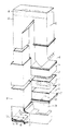
- the apparatus shown in fig. 1 consists of a telescopic down pipe 9, which forms a connecting channel between a container 10 for moulding material, preferably moulding sand, and a lower moulding chamber 5.
- the moulding material 8 is suggested by the wavy line in the container 10.
- the materials container 10 is moreover connected with an upper moulding chamber 4.
- a shared pattern carrier 1 is placed between the upper and the lower moulding chamber designated by 4 and 5, respectively, and to the said carrier are secured an upper and a lower half pattern, designated by 2 and 3, respectively.
- the moulding chambers 4 and 5 are defined upwardly and downwardly by squeeze plates 6 and 7, which are provided with inlet openings 17 for the moulding material.
- the squeeze plates 6 and 7 can form closed moulding spaces jointly with the moulding chambers 4 and 5 and the lower side of the shared pattern carrier 1.
- Moulding sand or other moulding material is injected through the openings in the squeeze plates into the said moulding spaces by impulsive intake. The intake will be provided by applying vacuum through the shared pattern carrier and/or the sides of the moulding chamber.
- post-compaction is made by feeding the squeeze plates 6 and 7, respectively, towards the shared pattern carrier.
- the squeeze plates are then moved away from the pattern carrier, which is removed from the area between the moulding chambers, and the two mould parts made are caused to close up so as to form a complete mould. Cores may have been inserted in advance in the mould impression provided in the mould parts.
- intake openings 13 are provided below the screen plate 15.
- the air sucked in through the openings 13 is discharged through a slot 16 between the screen plate 15 and the bottom of the down pipe, as indicated by the arrows. This generates a sort of air cushion, which "rinses" the bottom of the down pipe in its lower section 11.
- the lower section 11 of the down pipe is connected with the lower moulding chamber 5 through a connecting part 18, tapered in V-shape in the direction of the slot 17 in the squeeze plate 7.
- three circular air inlet openings 13 are provided at the lower corner of the L-shaped down pipe.
Landscapes
- Engineering & Computer Science (AREA)
- Mechanical Engineering (AREA)
- Casting Devices For Molds (AREA)
- Devices For Post-Treatments, Processing, Supply, Discharge, And Other Processes (AREA)
Priority Applications (1)
| Application Number | Priority Date | Filing Date | Title |
|---|---|---|---|
| AT87901408T ATE43522T1 (de) | 1986-02-26 | 1987-02-24 | Vorrichtung zur gleichzeitigen herstellung von ineinanderpassenden formenteilen mit horizontalen trennflaechen. |
Applications Claiming Priority (2)
| Application Number | Priority Date | Filing Date | Title |
|---|---|---|---|
| DK088686A DK159599C (da) | 1986-02-26 | 1986-02-26 | Apparat til samtidig fremstilling af sammenhoerende formparter med horisontal skilleflade |
| DK886/86 | 1986-02-26 |
Publications (2)
| Publication Number | Publication Date |
|---|---|
| EP0261157A1 EP0261157A1 (en) | 1988-03-30 |
| EP0261157B1 true EP0261157B1 (en) | 1989-05-31 |
Family
ID=8098639
Family Applications (1)
| Application Number | Title | Priority Date | Filing Date |
|---|---|---|---|
| EP87901408A Expired EP0261157B1 (en) | 1986-02-26 | 1987-02-24 | An apparatus for simultaneous making of matching mould parts with a horizontal parting face |
Country Status (10)
| Country | Link |
|---|---|
| US (1) | US4739820A (da) |
| EP (1) | EP0261157B1 (da) |
| JP (1) | JPS62199247A (da) |
| KR (1) | KR910001173B1 (da) |
| CN (1) | CN1006608B (da) |
| BR (1) | BR8706034A (da) |
| DK (1) | DK159599C (da) |
| SU (1) | SU1579447A3 (da) |
| UA (1) | UA6029A1 (da) |
| WO (1) | WO1987005239A1 (da) |
Family Cites Families (2)
| Publication number | Priority date | Publication date | Assignee | Title |
|---|---|---|---|---|
| DE2653788C2 (de) * | 1976-11-26 | 1981-08-27 | Bühler, Eugen, Dipl.-Ing., 8871 Burtenbach | Verfahren und Vorrichtung zum Herstellen von Gießformen aus bindemittelhaltigem Formsand |
| US4620584A (en) * | 1985-05-24 | 1986-11-04 | Witt Raymond H | Green sand mold filling system |
-
1986
- 1986-02-26 DK DK088686A patent/DK159599C/da not_active IP Right Cessation
- 1986-04-02 JP JP61074374A patent/JPS62199247A/ja active Granted
-
1987
- 1987-02-24 BR BR8706034A patent/BR8706034A/pt unknown
- 1987-02-24 CN CN87100907A patent/CN1006608B/zh not_active Expired
- 1987-02-24 EP EP87901408A patent/EP0261157B1/en not_active Expired
- 1987-02-24 WO PCT/DK1987/000017 patent/WO1987005239A1/en not_active Ceased
- 1987-02-24 UA UA4203608A patent/UA6029A1/uk unknown
- 1987-02-24 US US07/108,829 patent/US4739820A/en not_active Expired - Lifetime
- 1987-02-24 KR KR1019870700978A patent/KR910001173B1/ko not_active Expired
- 1987-10-23 SU SU874203608A patent/SU1579447A3/ru active
Also Published As
| Publication number | Publication date |
|---|---|
| DK88686D0 (da) | 1986-02-26 |
| KR910001173B1 (ko) | 1991-02-25 |
| BR8706034A (pt) | 1988-01-19 |
| SU1579447A3 (ru) | 1990-07-15 |
| DK159599B (da) | 1990-11-05 |
| US4739820A (en) | 1988-04-26 |
| JPS62199247A (ja) | 1987-09-02 |
| DK159599C (da) | 1991-04-29 |
| CN87100907A (zh) | 1987-10-28 |
| CN1006608B (zh) | 1990-01-31 |
| UA6029A1 (uk) | 1994-12-29 |
| EP0261157A1 (en) | 1988-03-30 |
| JPH0240411B2 (da) | 1990-09-11 |
| KR880700702A (ko) | 1988-04-11 |
| WO1987005239A1 (en) | 1987-09-11 |
| DK88686A (da) | 1987-08-27 |
Similar Documents
| Publication | Publication Date | Title |
|---|---|---|
| US3697208A (en) | Apparatus for filling molds | |
| US4739820A (en) | Apparatus for simultaneous making of matching mould parts with a horizontal parting face | |
| US4739821A (en) | Apparatus for making mould parts with a horizontal parting face | |
| JPS5521373A (en) | Apparatus for feeding plate material | |
| JPS55147462A (en) | Molding method of lower mold and squeeze plate device | |
| CN215660869U (zh) | 一种大吨位压砖机的成型机构 | |
| CN205572659U (zh) | 一种自动布料的压砖机 | |
| JP4123461B2 (ja) | 造型ライン及び鋳造ライン | |
| CN222090653U (zh) | 一种饼干粉料自动撒粉机 | |
| CN216064154U (zh) | 一种复式精选机挡料装置 | |
| CN211730071U (zh) | 一种注塑模具的排气结构 | |
| CN217725836U (zh) | 一种带有分料结构的v型选粉机 | |
| CN215660872U (zh) | 一种陶瓷模的透气装置 | |
| CN216234602U (zh) | 一种轴套自动上料机 | |
| DK161812B (da) | Formeindretning til fremstilling af en stoebeform samt anvendelse af samme | |
| JPS5813974Y2 (ja) | 成形品選別装置 | |
| JPH0155969B2 (da) | ||
| JPS6341096Y2 (da) | ||
| JPS5823180B2 (ja) | 自動造型機に於ける砂吹き込み装置 | |
| JPS5639147A (en) | Mold molding method and its device | |
| JPS59137154A (ja) | 均質充填密度の鋳型造型法 | |
| JPS6331707A (ja) | 自動車用内装基材の製造方法 | |
| JPS56158251A (en) | Vacuum molding method | |
| CN205616283U (zh) | 一种自动布料的压砖机 | |
| JPS62181103A (ja) | 脱水成形用型 |
Legal Events
| Date | Code | Title | Description |
|---|---|---|---|
| PUAI | Public reference made under article 153(3) epc to a published international application that has entered the european phase |
Free format text: ORIGINAL CODE: 0009012 |
|
| 17P | Request for examination filed |
Effective date: 19871021 |
|
| AK | Designated contracting states |
Kind code of ref document: A1 Designated state(s): AT BE CH DE FR GB IT LI LU NL SE |
|
| 17Q | First examination report despatched |
Effective date: 19881024 |
|
| GRAA | (expected) grant |
Free format text: ORIGINAL CODE: 0009210 |
|
| AK | Designated contracting states |
Kind code of ref document: B1 Designated state(s): AT BE CH DE FR GB IT LI LU NL SE |
|
| REF | Corresponds to: |
Ref document number: 43522 Country of ref document: AT Date of ref document: 19890615 Kind code of ref document: T |
|
| ITF | It: translation for a ep patent filed | ||
| REF | Corresponds to: |
Ref document number: 3760195 Country of ref document: DE Date of ref document: 19890706 |
|
| ET | Fr: translation filed | ||
| PGFP | Annual fee paid to national office [announced via postgrant information from national office to epo] |
Ref country code: FR Payment date: 19900123 Year of fee payment: 4 Ref country code: BE Payment date: 19900123 Year of fee payment: 4 |
|
| PGFP | Annual fee paid to national office [announced via postgrant information from national office to epo] |
Ref country code: SE Payment date: 19900216 Year of fee payment: 4 |
|
| PGFP | Annual fee paid to national office [announced via postgrant information from national office to epo] |
Ref country code: AT Payment date: 19900226 Year of fee payment: 4 |
|
| PG25 | Lapsed in a contracting state [announced via postgrant information from national office to epo] |
Ref country code: LU Free format text: LAPSE BECAUSE OF NON-PAYMENT OF DUE FEES Effective date: 19900228 |
|
| PGFP | Annual fee paid to national office [announced via postgrant information from national office to epo] |
Ref country code: NL Payment date: 19900228 Year of fee payment: 4 |
|
| PLBE | No opposition filed within time limit |
Free format text: ORIGINAL CODE: 0009261 |
|
| STAA | Information on the status of an ep patent application or granted ep patent |
Free format text: STATUS: NO OPPOSITION FILED WITHIN TIME LIMIT |
|
| 26N | No opposition filed | ||
| PG25 | Lapsed in a contracting state [announced via postgrant information from national office to epo] |
Ref country code: GB Effective date: 19910224 Ref country code: AT Effective date: 19910224 |
|
| PG25 | Lapsed in a contracting state [announced via postgrant information from national office to epo] |
Ref country code: SE Effective date: 19910225 |
|
| ITTA | It: last paid annual fee | ||
| PG25 | Lapsed in a contracting state [announced via postgrant information from national office to epo] |
Ref country code: BE Effective date: 19910228 |
|
| PG25 | Lapsed in a contracting state [announced via postgrant information from national office to epo] |
Ref country code: NL Effective date: 19910901 |
|
| NLV4 | Nl: lapsed or anulled due to non-payment of the annual fee | ||
| GBPC | Gb: european patent ceased through non-payment of renewal fee | ||
| PG25 | Lapsed in a contracting state [announced via postgrant information from national office to epo] |
Ref country code: FR Effective date: 19911031 |
|
| REG | Reference to a national code |
Ref country code: FR Ref legal event code: ST |
|
| PGFP | Annual fee paid to national office [announced via postgrant information from national office to epo] |
Ref country code: CH Payment date: 19940128 Year of fee payment: 8 |
|
| PGFP | Annual fee paid to national office [announced via postgrant information from national office to epo] |
Ref country code: DE Payment date: 19940412 Year of fee payment: 8 |
|
| EUG | Se: european patent has lapsed |
Ref document number: 87901408.2 Effective date: 19911008 |
|
| PG25 | Lapsed in a contracting state [announced via postgrant information from national office to epo] |
Ref country code: LI Effective date: 19950228 Ref country code: CH Effective date: 19950228 |
|
| PG25 | Lapsed in a contracting state [announced via postgrant information from national office to epo] |
Ref country code: DE Effective date: 19951101 |
|
| PG25 | Lapsed in a contracting state [announced via postgrant information from national office to epo] |
Ref country code: IT Free format text: LAPSE BECAUSE OF NON-PAYMENT OF DUE FEES;WARNING: LAPSES OF ITALIAN PATENTS WITH EFFECTIVE DATE BEFORE 2007 MAY HAVE OCCURRED AT ANY TIME BEFORE 2007. THE CORRECT EFFECTIVE DATE MAY BE DIFFERENT FROM THE ONE RECORDED. Effective date: 20050224 |