EP0261465A2 - Outil de fraisage des filetages - Google Patents
Outil de fraisage des filetages Download PDFInfo
- Publication number
- EP0261465A2 EP0261465A2 EP87112840A EP87112840A EP0261465A2 EP 0261465 A2 EP0261465 A2 EP 0261465A2 EP 87112840 A EP87112840 A EP 87112840A EP 87112840 A EP87112840 A EP 87112840A EP 0261465 A2 EP0261465 A2 EP 0261465A2
- Authority
- EP
- European Patent Office
- Prior art keywords
- milling
- plate
- edge
- chip guide
- thread
- Prior art date
- Legal status (The legal status is an assumption and is not a legal conclusion. Google has not performed a legal analysis and makes no representation as to the accuracy of the status listed.)
- Granted
Links
- 238000003801 milling Methods 0.000 title claims abstract description 179
- 230000001154 acute effect Effects 0.000 claims description 10
- 241001290722 Odontonema Species 0.000 claims description 2
- 238000009434 installation Methods 0.000 claims 1
- 230000002441 reversible effect Effects 0.000 abstract 1
- 238000013461 design Methods 0.000 description 4
- 238000003754 machining Methods 0.000 description 4
- 230000000630 rising effect Effects 0.000 description 3
- 210000001114 tooth apex Anatomy 0.000 description 3
- 230000002349 favourable effect Effects 0.000 description 2
- 239000011295 pitch Substances 0.000 description 2
- 230000007423 decrease Effects 0.000 description 1
- 238000011161 development Methods 0.000 description 1
- 230000018109 developmental process Effects 0.000 description 1
- 230000000694 effects Effects 0.000 description 1
- 238000012423 maintenance Methods 0.000 description 1
- 238000000034 method Methods 0.000 description 1
- 238000012545 processing Methods 0.000 description 1
- 230000000284 resting effect Effects 0.000 description 1
- 230000007704 transition Effects 0.000 description 1
- 230000003313 weakening effect Effects 0.000 description 1
Images

Classifications
-
- B—PERFORMING OPERATIONS; TRANSPORTING
- B23—MACHINE TOOLS; METAL-WORKING NOT OTHERWISE PROVIDED FOR
- B23G—THREAD CUTTING; WORKING OF SCREWS, BOLT HEADS, OR NUTS, IN CONJUNCTION THEREWITH
- B23G5/00—Thread-cutting tools; Die-heads
- B23G5/18—Milling cutters
- B23G5/182—Milling cutters combined with other tools
-
- B—PERFORMING OPERATIONS; TRANSPORTING
- B23—MACHINE TOOLS; METAL-WORKING NOT OTHERWISE PROVIDED FOR
- B23B—TURNING; BORING
- B23B27/00—Tools for turning or boring machines; Tools of a similar kind in general; Accessories therefor
- B23B27/06—Profile cutting tools, i.e. forming-tools
- B23B27/065—Thread-turning tools
-
- B—PERFORMING OPERATIONS; TRANSPORTING
- B23—MACHINE TOOLS; METAL-WORKING NOT OTHERWISE PROVIDED FOR
- B23B—TURNING; BORING
- B23B27/00—Tools for turning or boring machines; Tools of a similar kind in general; Accessories therefor
- B23B27/14—Cutting tools of which the bits or tips or cutting inserts are of special material
- B23B27/16—Cutting tools of which the bits or tips or cutting inserts are of special material with exchangeable cutting bits or cutting inserts, e.g. able to be clamped
- B23B27/1614—Cutting tools of which the bits or tips or cutting inserts are of special material with exchangeable cutting bits or cutting inserts, e.g. able to be clamped with plate-like cutting inserts of special shape clamped against the walls of the recess in the shank by a clamping member acting upon the wall of a hole in the insert
-
- B—PERFORMING OPERATIONS; TRANSPORTING
- B23—MACHINE TOOLS; METAL-WORKING NOT OTHERWISE PROVIDED FOR
- B23B—TURNING; BORING
- B23B2200/00—Details of cutting inserts
- B23B2200/36—Other features of cutting inserts not covered by B23B2200/04 - B23B2200/32
- B23B2200/3618—Fixation holes
-
- B—PERFORMING OPERATIONS; TRANSPORTING
- B23—MACHINE TOOLS; METAL-WORKING NOT OTHERWISE PROVIDED FOR
- B23B—TURNING; BORING
- B23B2270/00—Details of turning, boring or drilling machines, processes or tools not otherwise provided for
- B23B2270/16—Constructions comprising three or more similar components
Definitions
- the invention relates to a thread milling tool with a cutter shaft having a rotary milling axis, which has a receptacle with alignment surfaces for the abutment of a one-piece multi-tooth thread milling plate designed as an indexable insert, which is toothed according to the thread profile on at least one edge surface over the plate thickness and forms a thread milling edge with a plate edge of the respective edge surface which lies on the associated first plate side and is delimited by a cutting face which is formed by a chip guide surface which is essentially inclined with respect to the plate plane.
- Thread milling tool which is formed on a single plate side on several edges of the thread milling plate with thread milling edges so that it can be turned by rotation about an axis perpendicular to its plane of the plate can when a set of milling teeth is used.
- Thread milling tools of this type can be used both for producing internal threads and for external threads, the milling tool being arranged in a configuration which is approximately parallel, but eccentric, to the workpiece axis in order to carry out the main working movement and to set the workpiece at a relatively high speed in order to carry out the feed movement Workpiece axis is rotated.
- the thread milling edge can be at least as long as the length of the thread to be produced, so that the workpiece only executes essentially a single revolution until the thread is finished, and simultaneously simultaneously move the milling tool or the workpiece by one thread pitch per workpiece revolution becomes.
- the thread milling edge can, however, also be shorter than the thread to be produced, in which case it is then expedient first to produce a first section of the thread corresponding to the length of the thread milling edge, then to move the milling tool and the workpiece against one another approximately by the length of the thread milling edge and then another thread portion is made until the thread is finished to the predetermined length; In such a procedure in particular, the use of numerically controlled milling machines is expedient.
- the thread milling edges of such milling tools are extremely sensitive, in particular in the case of fine precision threads, which is why the arrangement of several thread milling edges on one and the same plate side can be poblematic in that the milling edges not in use are light during the work of the milling edge in use can be damaged.
- two edge surfaces of the thread milling plate must be machined, which in particular also means the precisely reproducible alignment of the milling plate with respect to the milling shank difficult because toothed edge surfaces are less suitable for this.
- the plate edges provided with thread milling edges should be of the same length, which amounts to a correspondingly large radial extension of the thread milling plate with respect to the milling axis with a relatively long thread length and leads to difficulties in the case of small internal thread diameters.
- the invention has for its object to provide a thread milling tool of the type mentioned, which allows different configurations for a variety of uses with a simple structure.
- the milling tool should also be easy to use, easy to sharpen and compact.
- the first-mentioned object is achieved in a thread milling tool of the type described at the outset in accordance with the invention in that at least one toothed thread milling edge is also provided on the second plate side, the cutting face of which is formed by a chip guide surface inclined relative to the plane of the milling plate.
- this thread milling edge lies concealed on the rear side of the milling plate and is therefore largely protected against damage.
- the milling edges can also be designed differently in terms of their toothing dimensions in a simple manner, for example in the sense that they correspond to different threads or are designed as pre-milling and on the other hand as fine machining finished milling edges.
- a particularly advantageous embodiment results, however, if two identical thread milling edges are formed by the two plate edges of at least one edge surface and if the chip guide surfaces on both sides of the plate are of essentially the same mirror-symmetrical design to the plate center plane.
- the toothing of the edge surface runs uniformly over the plate thickness, all that is required to form two identical milling edges is the machining of a single edge surface.
- the similarity of the two milling edges can be further increased by either the apex or the bottom surfaces of the toothing of the edge surface or both the apex and the bottom surfaces each lying in a plane perpendicular to the plane of the plate, which also means the tool alignment after turning In particular, it is considerably easier if the two plate sides form alignment surfaces that are parallel to each other or are designed as corresponding flat and possibly smooth surfaces.
- the toothing is provided in an oblique view in view of the associated edge surface, which can be selected, for example, so that the teeth on one The side of the plate is offset by one, two or more tooth pitches with respect to the teeth on the other side of the plate, so that the same tool orientation is still true after turning.
- this is generally only possible with thread profiles that still provide a sufficient clearance angle with respect to the longitudinal flanks of the toothing, there is a further simplification if the toothing passes through the plate thickness at right angles to the plate plane.
- the toothing runs non-uniformly over the length of the edge surface, for example decreases in apex height towards one end of the edge surface, so that a conically tapering thread can be produced.
- an inclined thread e.g. can be produced in that the tool axis is inclined at a small angle to the workpiece axis.
- the toothing is mirror-symmetrical to the center of the length of the associated edge surface.
- the tooth geometry on both plate edges of the respective edge surface are identical to the associated alignment surfaces of the milling plate with regard to their tooth geometry.
- a high cutting speed with a clean chip flow can be achieved above all if the milling edge has an acute cutting angle between 60 ° and 85 °, preferably about 75 °.
- This can be achieved, for example, in a simple manner in that the chip guide surface is essentially under one acute, opening angle to the associated edge surface between 5 ° and 30 °, preferably about 15 °, to the plate center plane lying between the two sides of the plate.
- the cutting plate in the region of this edge surface has a dovetail profile that extends, at most, up to the planes of its insert sides, onto which, for example, a correspondingly profiled, for example strip-shaped hood made of plastic or the like is pushed to protect the milling edges can be and that also allows a very cheap storage and availability of milling plates in, for example, standing dovetail grooves of a holding device. Furthermore, it is possible to re-sharpen both milling edges in a single pass by simultaneously machining both chip guide surfaces in a single pass, so that the tool is extremely easy to maintain.
- the cutting behavior and the resharpenability can be further improved in that the chip guide surface is essentially flat following the milling edge, in particular over most of its width or beyond the bottom surfaces of the toothing. So that the chips run even better, the chip guide surface expediently rises at a distance from the milling edge or from the bottom surfaces of the toothing to the associated plate side at an angle greater than the inclination angle in the region of the milling edge of in particular approximately 45 °.
- the chip guide surface at a distance from the milling edge becomes essentially tangentially into a concave fillet, the central axis of which is preferably approximately in the plane of the associated plate side and which is also expediently in the rising, also strip-shaped planes lying at a distance from the milling edge Section of the chip guide surface passes tangentially, i.e. without edges.
- the total width of the chip guide surface is approximately half the plate thickness of the thread milling plate, so that there is only a very slight weakening of the plate thickness.
- a small width of the chip guide surface can also be achieved in that the deepest point of the chip guide surface is approximately the same distance from the bottom surfaces of the tooth system as from the boundary of the chip guide surface that is removed from the tooth system.
- the milling edge is expediently provided on the longest edge surface of the milling plate, i.e. the axial extent of the milling plate with respect to the milling tool is greater than the associated radial extent. Nevertheless, a very good alignment of the milling plate can be achieved if it is not, as is also conceivable, triangular, but trapezoidal, whereby an acute trapezoidal angle of preferably approximately 60 ° is advantageously provided, ie that the alignment surfaces formed by edge surfaces of the milling plate are below are at an angle of about 60 ° to each other.
- the chip guide surface runs over the entire length of the associated edge surface.
- the milling plate is penetrated by a through opening for a clamping bolt immediately adjacent to the chip guide surface.
- This through opening is expediently expanded on both sides of the plate in the shape of a truncated cone at an acute cone angle of, for example, about 60 ° in such a way that its boundary edge on the respective side of the plate is close is touched too tangentially by the chip guide surface.
- the through opening or their frustoconical end sections are expediently slightly eccentric to a clamping bolt receiving opening, such as a threaded bore, in the milling shank, so that when a head with a frustoconical shape is tightened on the truncated cone Extension of the clamping bolt, the milling plate is loaded or pressed against the alignment surfaces of the milling shank.
- the mounting for the milling plate is formed by a recess in the milling shank which is adapted to its outer shape and which preferably forms the alignment surfaces for the milling plate exclusively with its bottom surface and two edge surfaces lying at an angle to one another.
- the milling axis lies between the planes of the plate sides of the milling plate, preferably approximately in the plane of the chip guide surface of the milling edge in the milling position.
- the milling axis may lie in a closer proximity to the plate edge facing away from the toothed edge surface and preferably this parallel plate edge, or even essentially in this plate edge, in comparison with the plate thickness.
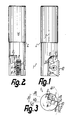
- a thread milling tool 1 can consist of only three one-piece parts, namely an essentially cylindrical milling shank 2, an essentially constant thick milling plate 3 and a clamping bolt 4 provided with a countersunk head and a metric threaded shank.
- the receptacle 6 is formed by a recess in a plane bottom surface lying approximately in an axial plane of the milling cutter shaft 2 of a chip chamber 9 which is angularly limited in view of the bottom surface and extends to the front end face of the milling cutter shaft 2 and over a little more than half the length of its working end formed, the width at right angles to the milling cutter axis 5 is only slightly larger than the associated extension of the part of the milling plate 3 which engages in the milling cutter shaft 2.
- the depth of the receptacle 6 is approximately the same or only slightly smaller than the plate thickness of the milling plate 3, the bottom surface of the receptacle 6 parallel to the bottom surface of the chip chamber 9 being one of three alignment surfaces 7, 8 which are at an angle to one another, namely that to the plate contour of the milling plate 3 forms approximately the same area, consistently flat alignment surface 7, on which the milling plate 3 rests with one plate side and which is penetrated by the threaded bore for receiving the clamping bolt 4.
- the two other alignment surfaces 8 are formed by two edge surfaces of the receptacle 6, which are at an acute angle to one another and diverging from the outer circumference of the milling cutter shank 2, of which the alignment outer surface 8 lying adjacent to the front end of the milling cutter shank 2 approximates the associated front one ,
- the end face of the cutter shank 2, which is at right angles to the cutter axis 5, extends, while the corresponding end of the alignment surface 8 behind and opposite is at a distance from the associated end of the chip chamber 9.
- the milling plate 3 which has a trapezoidal shape in view of its plate sides, has two milling edges 11, 12, which face away from one another or lie on both sides of the plate 13, 14, only on their longest edge surface 10 formed by the base edge of the trapezoidal shape, each facing the plane of the associated plate side 13, 14 are set back only slightly and are identical in terms of their geometric shape.
- Each milled edge 11, 12 is assigned a rounded, obtuse-angled, angular groove-shaped chip guide surface 15, 16, the flat portion of which adjoins the toothed milled edges 11, 12 forms the cutting face 17, 18.
- the milling plate 3 thus has a dovetail-shaped edge profile along the edge surface 10, the smallest thickness of which is only about a quarter smaller than the plate thickness 20 of the milling plate 3, the dovetail profile being formed symmetrically to the central plane 19 of the plate.
- Both the tooth apex 24 on the one hand and the bottom surfaces 25 of the tooth gaps 23 on the other are each in a common plane parallel to the longitudinal direction of the edge surface 10 and perpendicular to the plate center plane 19, the tooth apex 24 being slightly rounded and the bottom surfaces 25 in this way are flat that they merge into the flat tooth flanks at an obtuse angle.
- the depth of the tooth gaps 23 is approximately equal to half the total width of the respective chip guide surface, measured between the tooth vertices and the boundary away therefrom.
- At the two ends of the edge surface 10 there are no tooth flanks or teeth 22, but rather sections of floor surfaces 25 adjoining the outermost teeth, tooth gaps limited only on one side by flanks, the width of these end floor surfaces 25 being greater than half the width of the central floor surfaces and preferably is smaller than the width of such a floor area.
- the edge surface 10 or the milling edges 11, 12 or the teeth 21 are symmetrical to a central plane 27 perpendicular to the plate center plane 19 and to the edge surface 10, which goes through the center of the length 26 of the edge surface 10.
- the entire milling plate 3 is mirror-symmetrical to this central plane 27.
- the cylindrical inner contour of a workpiece 41 is indicated by dash-dotted lines, into which an internal thread is to be milled.
- This inner contour which corresponds to the inner or core diameter, is shown in a position in which it still has to be moved to thread depth relative to the milling edge 11 intended for milling use, the milling tool or the milling plate 3 or the milling edge 11 being in the position is shown in which it engages the deepest in the workpiece when rotating about the milling axis 5, that is to say that the milling edge 11 or the associated cutting face 17 lies in the common axial plane of the milling axis 5 and the workpiece axis 42.
- the cutting angle of the milling edge 11 is designated 28 and is 75 ° in the exemplary embodiment shown. Compared to the workpiece 41, in this position there is an average clearance angle 29 of approximately 15 ° and the cutting edge-breast angle 30 is approximately 15 °.
- the chip guiding surface 15 or 16 is in each case continuously smooth, but penetrated by the toothing 21 about half its width and, in addition to the section forming the respective cutting face 17 or 18, on the side facing away from the edge surface 10 is relatively steep to the associated plate side 13, 14 rising section 31, these two sections lying at an obtuse angle of approximately 115 ° to one another in cross-section merging tangentially into one another via an approximately part-circular or smaller than quarter-circular fillet 32, the central axis of which approximately in the plane of the associated plate side 13 or 14 at a greater distance from the edge surface 10 than the distance from it reversed boundary 35 of the chip guide surface 15 or 16.
- the section 31 of the chip guide surface 15 or 16 transitions at an obtuse angle into the associated plane and the plate side 13 or 14 parallel to the central plane 19 of the plate.
- the overall width 33 of the chip guide surface 15 or 16 is determined by the boundary 35, the lowest point 34 of which lies in the region of the fillet 32 and the thinnest zone of the milling plate 3.
- edge surfaces 36 of the milling plate 3 adjoining the edge surface 10 at an acute angle lie mirror-symmetrically on both sides of the central plane 27 and at an acute angle to one another, their length being approximately one third shorter than the length 26 of the edge surface 10.
- the obtuse angle adjoining these edge surfaces 36, facing away from the edge surface 10 and parallel to this edge surface 37, is also flat, but is not used for abutment or alignment in the milling shank 2, i.e. that it lies essentially without contact therein; their length is approximately one third of the length 26 of the edge surface 10.
- All edge surfaces 10, 36, 37 are at right angles to the planes 38, 39 of the two plate sides 13, 14, the edges of the edge surfaces 36, 37 on both plate sides 13, 14 being such are chamfered so that they do not extend to the respective fillet 32 at the ends of the chip guiding surfaces 15, 16 with these chamfers, but at most only about half the height of the associated rising section 31.
- the axial plane of the milling tool passing through the tips and the bottom edges of the milling edge 11 is designated by 40.
- the milling plate 3 is penetrated immediately adjacent to the chip guide surfaces 15, 16 by a centrally symmetrical through opening 23, the central axis of which is perpendicular to the central plate plane 19 in the central plane 27 and opposite the edge surface 37, for example, by approximately one Has a quarter smaller distance than the plane of the tooth apex 24.
- the passage opening 43 has or forms on both plate sides 13, 14 acute-angled frustoconical end sections 44, 45 of 60 ° cone angle, which are the same in terms of their largest diameter and in terms of the cone angle and can also have the same axial extent of about a third of the plate thickness 20.
- a cylindrical middle section 46 Provided between these two end sections 44, 45 is a cylindrical middle section 46, the diameter of which corresponds to the smallest diameter of at least one end section 44, the diameter of this middle section 46 being larger than the shaft of the clamping bolt 4, as is the diameter of the respective end section 44, 45 compared to the frustoconical head of the clamping bolt 4 with the same cone angle, so that it can engage in an eccentrically lying manner in the direction of the edge surface 37 in the through opening 43 and rests exclusively with its head on the side of the associated end section 44, 45 facing away from the edge surface 10; as a result, when tightening the clamping bolt 4 on the milling plate 3, in addition to a direction directed against the aligning surface 7, a force which pulls the milling plate 3 parallel to this aligning surface 7 into the receptacle 6 is exerted, so that the milling plate 3 is tightened by tightening a single clamping bolt 4 clamped against the alignment surfaces 8 and thereby adjusted precisely determinable.
- the cylindrical middle section 46 between the cylindrical middle section 46 and a shorter one of the two end sections 44, 45 there is still a cylindrical intermediate section 47 of the through opening 43, the diameter of which is slightly larger than that of the middle section 46 and equal to the smallest diameter of the associated end section 45, but the axial extent thereof is significantly smaller than that of all other sections.
- the intermediate section 47 forms a shoulder surface which is perpendicular to the central axis of the through opening 43 and a cylindrical zen adjoining this Trier complexity and can be used for precise alignment of the milling plate 3 perpendicular to the plate center plane 19 and in all directions radially to the central axis of the through hole 43, for example when machining, resharpening and the like of the milling plate 3.
Landscapes
- Engineering & Computer Science (AREA)
- Mechanical Engineering (AREA)
- Milling Processes (AREA)
- Turning (AREA)
Applications Claiming Priority (2)
| Application Number | Priority Date | Filing Date | Title |
|---|---|---|---|
| DE19863632296 DE3632296A1 (de) | 1986-09-23 | 1986-09-23 | Gewinde-fraeswerkzeug |
| DE3632296 | 1986-09-23 |
Publications (3)
| Publication Number | Publication Date |
|---|---|
| EP0261465A2 true EP0261465A2 (fr) | 1988-03-30 |
| EP0261465A3 EP0261465A3 (en) | 1989-05-31 |
| EP0261465B1 EP0261465B1 (fr) | 1994-11-09 |
Family
ID=6310153
Family Applications (1)
| Application Number | Title | Priority Date | Filing Date |
|---|---|---|---|
| EP87112840A Expired - Lifetime EP0261465B1 (fr) | 1986-09-23 | 1987-09-03 | Outil de fraisage des filetages |
Country Status (4)
| Country | Link |
|---|---|
| EP (1) | EP0261465B1 (fr) |
| JP (1) | JPH0811330B2 (fr) |
| AT (1) | ATE113879T1 (fr) |
| DE (2) | DE3632296A1 (fr) |
Cited By (3)
| Publication number | Priority date | Publication date | Assignee | Title |
|---|---|---|---|---|
| WO2000030791A1 (fr) * | 1998-11-19 | 2000-06-02 | Ford Motor Company | Outil de coupe |
| EP2420340A1 (fr) * | 2010-08-20 | 2012-02-22 | VARGUS Ltd. | Fraise à fileter et insert pour filetage par fraisage |
| EP3715033A1 (fr) | 2019-03-26 | 2020-09-30 | VARGUS Ltd. | Procédé de détermination de paramètres de fraisage, procédé de fraisage de fils et utilisation d'une fraise à fileter |
Families Citing this family (9)
| Publication number | Priority date | Publication date | Assignee | Title |
|---|---|---|---|---|
| JPH0270929U (fr) * | 1988-11-12 | 1990-05-30 | ||
| DE19958636A1 (de) * | 1999-12-04 | 2001-06-07 | Vargus Ltd | Fräswerkzeug und -einsatz, insbesondere Gewindefräser |
| DE10222048B4 (de) * | 2002-05-14 | 2005-11-24 | Vargus Ltd. | Werkzeug und Verfahren zur Maschinenbearbeitung von Werkstücken |
| RU2300449C2 (ru) * | 2005-08-30 | 2007-06-10 | Московский государственный технологический университет "СТАНКИН" | Резцовая головка для фрезерования внутренней резьбы |
| RU2412028C1 (ru) * | 2009-10-22 | 2011-02-20 | Российская Федерация, от имени которой выступает государственный заказчик - Министерство промышленности и торговли Российской Федерации | Резцовая головка для фрезерования внутренней резьбы |
| RU2438834C1 (ru) * | 2010-04-27 | 2012-01-10 | федеральное государственное бюджетное образовательное учреждение высшего профессионального образования "Московский государственный технологический университет "СТАНКИН"(ФГБОУ ВПО МГТУ "СТАНКИН") | Резцовая головка для обработки внутренних цилиндрических поверхностей |
| RU2453406C1 (ru) * | 2011-02-08 | 2012-06-20 | Федеральное государственное бюджетное образовательное учреждение высшего профессионального образования Московский государственный технологический университет "СТАНКИН" (ФГБОУ ВПО МГТУ "СТАНКИН") | Сборная резьбовая головка для планетарного формообразования внутренней резьбы |
| JP2013056396A (ja) * | 2011-09-08 | 2013-03-28 | Osg Corp | インデキサブル式ねじ切りフライス |
| RU2492975C1 (ru) * | 2012-05-24 | 2013-09-20 | Федеральное государственное бюджетное образовательное учреждение высшего профессионального образования "Российский университет дружбы народов" (РУДН) | Резцовая головка для фрезерования внутренней резьбы |
Family Cites Families (11)
| Publication number | Priority date | Publication date | Assignee | Title |
|---|---|---|---|---|
| GB130717A (en) * | 1918-06-29 | 1919-07-29 | Herbert Stuart Walker | Improvements in Tools for Chasing Screw Threads and in Holders therefor. |
| US2004333A (en) * | 1934-03-28 | 1935-06-11 | Oster Mfg Co | Chaser holder |
| NO135738C (fr) * | 1971-05-28 | 1977-05-25 | Sandvik Ab | |
| JPS5341796U (fr) * | 1976-09-14 | 1978-04-11 | ||
| US4360297A (en) * | 1978-06-02 | 1982-11-23 | Kennametal Inc. | Cutting insert |
| US4312250A (en) * | 1980-01-16 | 1982-01-26 | Yankoff Gerald K | Cutting insert and method of machining therewith |
| DE3114104A1 (de) * | 1981-04-08 | 1982-10-28 | Sandvik AB, 81181 Sandviken | Schneideinsatz zum gewindeschneiden |
| GB2096509B (en) * | 1981-04-13 | 1985-09-18 | Valeron Corp | A cutting tool and method for forming threads on a workpiece |
| SE453267B (sv) * | 1983-02-21 | 1988-01-25 | Seco Tools Ab | Gengsvarvningssker |
| GB8327581D0 (en) * | 1983-10-14 | 1983-11-16 | Stellram Ltd | Thread cutting |
| US4531863A (en) * | 1984-01-31 | 1985-07-30 | The Ingersoll Cutting Tool Company | Thread-cutting apparatus |
-
1986
- 1986-09-23 DE DE19863632296 patent/DE3632296A1/de active Pending
-
1987
- 1987-09-03 EP EP87112840A patent/EP0261465B1/fr not_active Expired - Lifetime
- 1987-09-03 DE DE3750741T patent/DE3750741D1/de not_active Expired - Fee Related
- 1987-09-03 AT AT87112840T patent/ATE113879T1/de not_active IP Right Cessation
- 1987-09-22 JP JP62236397A patent/JPH0811330B2/ja not_active Expired - Fee Related
Cited By (5)
| Publication number | Priority date | Publication date | Assignee | Title |
|---|---|---|---|---|
| WO2000030791A1 (fr) * | 1998-11-19 | 2000-06-02 | Ford Motor Company | Outil de coupe |
| US6276244B1 (en) | 1998-11-19 | 2001-08-21 | Visteon Global Technologies, Inc. | Cutting tool for forming parallel grooves in a tubular member |
| EP2420340A1 (fr) * | 2010-08-20 | 2012-02-22 | VARGUS Ltd. | Fraise à fileter et insert pour filetage par fraisage |
| US8602694B2 (en) | 2010-08-20 | 2013-12-10 | Vargus Ltd. | Thread-milling cutter and thread-milling insert |
| EP3715033A1 (fr) | 2019-03-26 | 2020-09-30 | VARGUS Ltd. | Procédé de détermination de paramètres de fraisage, procédé de fraisage de fils et utilisation d'une fraise à fileter |
Also Published As
| Publication number | Publication date |
|---|---|
| ATE113879T1 (de) | 1994-11-15 |
| JPS63162116A (ja) | 1988-07-05 |
| JPH0811330B2 (ja) | 1996-02-07 |
| EP0261465A3 (en) | 1989-05-31 |
| DE3750741D1 (de) | 1994-12-15 |
| EP0261465B1 (fr) | 1994-11-09 |
| DE3632296A1 (de) | 1988-04-07 |
Similar Documents
| Publication | Publication Date | Title |
|---|---|---|
| DE69521848T2 (de) | Ein drehender Fräser | |
| EP0674560B1 (fr) | Outil de forage a piece de coupe rapportee interchangeable | |
| EP0750960B1 (fr) | Foret, en particulier pour matériaux métalliques | |
| DE69520233T2 (de) | Universelle schneideinsatzaufnahme für tiefschneide- und planfräser | |
| EP0472563B1 (fr) | Outil a magasin interchangeable deplacable | |
| DE69300690T2 (de) | Bohrkopf. | |
| DE3831535A1 (de) | Stirnfraeser | |
| DE2110078A1 (de) | Werkzeug zur spanabhebenden Bear bettung, insbesondere Frasmesserkopf | |
| DE2615609B2 (de) | Fräswerkzeug | |
| CH616611A5 (fr) | ||
| DE3832547A1 (de) | Messerplatte fuer die praezisionsbearbeitung insbesondere von bohrungen | |
| EP0261465B1 (fr) | Outil de fraisage des filetages | |
| DE102015115310A1 (de) | Wirbelwerkzeug | |
| EP0486791A2 (fr) | Outil à aléser | |
| DE10030297A1 (de) | Bohrwerkzeug | |
| DE7728438U1 (de) | Stirnmesserkopf zum Verzahnen von Zahnrädern | |
| EP0749795A1 (fr) | Outil de perçage | |
| EP1742755B1 (fr) | Plaquette de coupe et outil pour usinage par enlevement de copeaux de surfaces de forage | |
| EP0144073B1 (fr) | Outil de coupe | |
| EP0542056A1 (fr) | Outil de coupe, spécialement fraise à fileter | |
| WO1995029783A1 (fr) | Outil de perçage | |
| DE3742740C1 (de) | Feinbohrwerkzeug | |
| EP2420337B1 (fr) | Plaquette réversible servant à chanfreiner, et combinaison d'une tête de fraisage conique ou cylindrique et d'une plaquette réversible servant à chanfreiner | |
| EP1027186B1 (fr) | Outil pour l'usinage fin de surfaces d'alesages | |
| EP0823300B1 (fr) | Plaquette de fraisage pour fraises |
Legal Events
| Date | Code | Title | Description |
|---|---|---|---|
| PUAI | Public reference made under article 153(3) epc to a published international application that has entered the european phase |
Free format text: ORIGINAL CODE: 0009012 |
|
| AK | Designated contracting states |
Kind code of ref document: A2 Designated state(s): AT BE CH DE FR GB IT LI LU NL SE |
|
| PUAL | Search report despatched |
Free format text: ORIGINAL CODE: 0009013 |
|
| AK | Designated contracting states |
Kind code of ref document: A3 Designated state(s): AT BE CH DE FR GB IT LI LU NL SE |
|
| 17P | Request for examination filed |
Effective date: 19891014 |
|
| 17Q | First examination report despatched |
Effective date: 19910116 |
|
| RAP1 | Party data changed (applicant data changed or rights of an application transferred) |
Owner name: VARGUS LTD. |
|
| GRAA | (expected) grant |
Free format text: ORIGINAL CODE: 0009210 |
|
| AK | Designated contracting states |
Kind code of ref document: B1 Designated state(s): AT BE CH DE FR GB IT LI LU NL SE |
|
| PG25 | Lapsed in a contracting state [announced via postgrant information from national office to epo] |
Ref country code: IT Free format text: LAPSE BECAUSE OF FAILURE TO SUBMIT A TRANSLATION OF THE DESCRIPTION OR TO PAY THE FEE WITHIN THE PRESCRIBED TIME-LIMIT;WARNING: LAPSES OF ITALIAN PATENTS WITH EFFECTIVE DATE BEFORE 2007 MAY HAVE OCCURRED AT ANY TIME BEFORE 2007. THE CORRECT EFFECTIVE DATE MAY BE DIFFERENT FROM THE ONE RECORDED. Effective date: 19941109 Ref country code: FR Effective date: 19941109 Ref country code: BE Effective date: 19941109 Ref country code: NL Effective date: 19941109 |
|
| REF | Corresponds to: |
Ref document number: 113879 Country of ref document: AT Date of ref document: 19941115 Kind code of ref document: T |
|
| REF | Corresponds to: |
Ref document number: 3750741 Country of ref document: DE Date of ref document: 19941215 |
|
| GBT | Gb: translation of ep patent filed (gb section 77(6)(a)/1977) |
Effective date: 19941213 |
|
| PG25 | Lapsed in a contracting state [announced via postgrant information from national office to epo] |
Ref country code: SE Effective date: 19950209 |
|
| EN | Fr: translation not filed | ||
| NLV1 | Nl: lapsed or annulled due to failure to fulfill the requirements of art. 29p and 29m of the patents act | ||
| PG25 | Lapsed in a contracting state [announced via postgrant information from national office to epo] |
Ref country code: AT Effective date: 19950903 |
|
| PLBE | No opposition filed within time limit |
Free format text: ORIGINAL CODE: 0009261 |
|
| STAA | Information on the status of an ep patent application or granted ep patent |
Free format text: STATUS: NO OPPOSITION FILED WITHIN TIME LIMIT |
|
| PG25 | Lapsed in a contracting state [announced via postgrant information from national office to epo] |
Ref country code: LU Free format text: LAPSE BECAUSE OF NON-PAYMENT OF DUE FEES Effective date: 19950930 |
|
| 26N | No opposition filed | ||
| REG | Reference to a national code |
Ref country code: GB Ref legal event code: IF02 |
|
| PGFP | Annual fee paid to national office [announced via postgrant information from national office to epo] |
Ref country code: GB Payment date: 20050819 Year of fee payment: 19 |
|
| PGFP | Annual fee paid to national office [announced via postgrant information from national office to epo] |
Ref country code: CH Payment date: 20050923 Year of fee payment: 19 |
|
| PGFP | Annual fee paid to national office [announced via postgrant information from national office to epo] |
Ref country code: DE Payment date: 20051031 Year of fee payment: 19 |
|
| PG25 | Lapsed in a contracting state [announced via postgrant information from national office to epo] |
Ref country code: LI Free format text: LAPSE BECAUSE OF NON-PAYMENT OF DUE FEES Effective date: 20060930 Ref country code: CH Free format text: LAPSE BECAUSE OF NON-PAYMENT OF DUE FEES Effective date: 20060930 |
|
| PG25 | Lapsed in a contracting state [announced via postgrant information from national office to epo] |
Ref country code: DE Free format text: LAPSE BECAUSE OF NON-PAYMENT OF DUE FEES Effective date: 20070403 |
|
| REG | Reference to a national code |
Ref country code: CH Ref legal event code: PL |
|
| GBPC | Gb: european patent ceased through non-payment of renewal fee |
Effective date: 20060903 |
|
| PG25 | Lapsed in a contracting state [announced via postgrant information from national office to epo] |
Ref country code: GB Free format text: LAPSE BECAUSE OF NON-PAYMENT OF DUE FEES Effective date: 20060903 |