EP0262624B1 - Système de régulation de position - Google Patents
Système de régulation de position Download PDFInfo
- Publication number
- EP0262624B1 EP0262624B1 EP87114075A EP87114075A EP0262624B1 EP 0262624 B1 EP0262624 B1 EP 0262624B1 EP 87114075 A EP87114075 A EP 87114075A EP 87114075 A EP87114075 A EP 87114075A EP 0262624 B1 EP0262624 B1 EP 0262624B1
- Authority
- EP
- European Patent Office
- Prior art keywords
- data
- position data
- time
- compensation
- present position
- Prior art date
- Legal status (The legal status is an assumption and is not a legal conclusion. Google has not performed a legal analysis and makes no representation as to the accuracy of the status listed.)
- Expired - Lifetime
Links
Images

Classifications
-
- G—PHYSICS
- G05—CONTROLLING; REGULATING
- G05B—CONTROL OR REGULATING SYSTEMS IN GENERAL; FUNCTIONAL ELEMENTS OF SUCH SYSTEMS; MONITORING OR TESTING ARRANGEMENTS FOR SUCH SYSTEMS OR ELEMENTS
- G05B19/00—Program-control systems
- G05B19/02—Program-control systems electric
- G05B19/18—Numerical control [NC], i.e. automatically operating machines, in particular machine tools, e.g. in a manufacturing environment, so as to execute positioning, movement or co-ordinated operations by means of program data in numerical form
- G05B19/19—Numerical control [NC], i.e. automatically operating machines, in particular machine tools, e.g. in a manufacturing environment, so as to execute positioning, movement or co-ordinated operations by means of program data in numerical form characterised by positioning or contouring control systems, e.g. to control position from one programmed point to another or to control movement along a programmed continuous path
-
- G—PHYSICS
- G05—CONTROLLING; REGULATING
- G05B—CONTROL OR REGULATING SYSTEMS IN GENERAL; FUNCTIONAL ELEMENTS OF SUCH SYSTEMS; MONITORING OR TESTING ARRANGEMENTS FOR SUCH SYSTEMS OR ELEMENTS
- G05B2219/00—Program-control systems
- G05B2219/30—Nc systems
- G05B2219/41—Servomotor, servo controller till figures
- G05B2219/41203—Lead-phase compensation, lag-phase compensation servo
Definitions
- This invention relates to a positioning control system which can be used for positioning control in various power units such as an electric motor and a hydraulic cylinder and, more particularly, to an improvement in lead compensation in the positioning control system and, more particularly, to employment of time data as a lead compensation parameter in such system and, further, to such system having a learning function.
- the simplest example of lead compensation is mounting of a limit switch or the like detection device at a position shifted from a desired position by an amount of lead compensation.
- the amount of time delay however is not uniform but is varied depending upon the operation speed of the machine.
- the amount of lead compensation must therefore be varied in accordance with the speed of the machine so that the mounting position of the switch or the like must be changed each time the speed of the machine is changed.
- a positioning control system (EP-A 0 135-754) according to which a position detector capable of continuously detecting position of a machine is provided instead of using a limit switch or the like and a target position detection output is obtained by comparing position detection data of the position detector with an established target position value.
- lead compensation is achieved by detecting the speed of the machine, obtaining the amount of lead compensation in response to the detected speed and correcting position detection data or target position data in accordance with this amount of lead compensation.
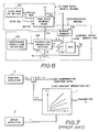
- the principle of this system is shown in Fig. 7. In Fig.
- a lead amount ⁇ a is obtained by a lead amount operation circuit 1 in accordance with speed ⁇ of the machine obtained by a speed detector 2 and lead compensation parameter a establised depending upon operation conditions of the machine and lead compensation is achieved by adding the lead amount ⁇ a and position data X detected by a position detector 3 together and thereby advancing, in appearance, data representing the present position of the machine by the lead amount ⁇ a.
- the operation circuit 1 may be so constructed that the lead amount ⁇ a is obtained by implementing operation of a predetermined function f ( ⁇ ) in real time or that a memory prestoring lead amounts ⁇ a corresponding to various speeds of the machine is provided and corresponding lead amount is read out in response to the speed ⁇ of the machine.
- the prior art system has the disadvantages that the provision of the speed detector results in high manufacturing cost, that in case the operation of the function f ( ⁇ ) for obtaining the lead amount is performed in real time, operation time required gives rise to time delay and that in case the speed is obtained by computing the position detection data, operation time required gives rise to time delay also.
- a positioning control system which comprises position detection means for detecting present position of an object to be controlled and supplying detected present position data; setting means for setting target position data; data supply means for supplying compensation parameter data; compensation means for correcting at least one of said present position data supplied from said position detection means and target position data supplied from setting means in accordance with said compensation parameter data; and control signal generation means for generating a control signal relating to the position of said object in accordance with the present position data and the target position data as corrected by said compensation means, characterized in that a memory means stores position data supplied from said position detection means, said data supply means supplies variable time data as said compensation parameter data, and said compensation means takes out from said memory means position data which precedes said present position data by a time corresponding to said supplied time data and corrects at least one of said present position data and said target position data in accordance with difference between said taken-out position data and present position data.
- FIG. 2 An example of locus of position data detected by the position detection means with respect to lapse of time is shown in Fig. 2.
- This position data is stored in the memory means.
- the compensation means takes out position data X (- ⁇ t) which is preceding the present time point by ⁇ t from the memory means and corrects at least one of present position data and target position data, using difference ⁇ x between the taken out position data and the present position data as the lead compensation amount.
- the compensation means adds ⁇ x to the present position data and thereby causes the present position data in appearance to advance by the lead compensation amount ⁇ x.
- the present position data in appearance which has been comensated for lead is one estimating position of the object at a time point which is ⁇ t after the present time.
- position after ⁇ t can be estimated by adding the difference ⁇ x in position at the time point ⁇ t before.
- the time data ⁇ t may be supplied suitably in accordance with a desired lead compensation amount. If, for example, a stop positioning control is performed by using a brake system, time ⁇ t required from an instant at which braking is applied till an instant at which the object actually stops is estimated and this ⁇ t is supplied as the time data. In this case, the difference ⁇ x corresponds to an estimated amount of sliding of the brake corresponding to the time ⁇ t.
- the compensation means effects lead compensation corresponding to this estimated amount of sliding of the brake by using this ⁇ x as the lead compensation amount in the positioning control.
- ⁇ t needs not be a known fixed value but may be established and changed suitably. The same operation is performed not only in the above described stop control using the braking system but in other types of positioning controls by supplying the time data ⁇ t corresponding to a desired lead compensation amount.
- correction means for detecting an error between a target position and an actually obtained position to correct the time data ⁇ t in accordance with this error.
- time data ⁇ t ⁇ t1 and error between a target position T and an actually obtained position B is - d2 as shown in Fig. 3a
- A represents a position at a time point at which the positioning command (e.g., a brake-on command) is issued.
- a learning function (previous learning function) is realized by constantly correcting time data used in the lead compensation whereby the problems of change in load condition on the machine and change in the characteristics of the machine due to aging are overcome and an accurate positioning control can be realized.
- position data to be take out of the memory means should preferably be one which is as near to the present time point as possible.
- position data which is preceding by ⁇ t/N (where N is any natural number) corresponding to 1/N of time ⁇ t which has been supplied as the lead compensation parameter is taken out of the memory means and difference ⁇ x between the taken out position data and the present position data is substantially multiplied by N to obtain difference N ⁇ ⁇ x corresponding to the established time ⁇ t and this N ⁇ ⁇ x is used as the lead compensation amount.
- N any natural number
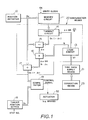
- a position detector 10 detects position of an object of the positioning control and outputs digital position data Dx. If the object of the positioning control is a rotating device such as a motor, a rotational type position detector is used whereas if the object of the positioning control is a linearly displacing device such as a cylinder, a linear type position detector is used.
- a memory circuit 11 sequentially stores the detected position data Dx in response to a write clock pulse CK and is constructed of a shift register or a RAM (random access memory).
- Time data supply means 21 supplies time data as a lead compensation parameter. Time corresponding to the supplied time data is referred to as established lead time ⁇ t. Compensation means 22 takes out position data which is preceding by length of time corresponding to the supplied time data from the memory circuit 11 and corrects at least one of present position data and target position data by using difference between the taken out position data and the present position data as a lead compensation amount.
- Correction means 23 detects an error between a target position and an actual stop position and corrects the time data supplied to the time data supply means 21 in accordance with this error.
- a logic circuit 13 establishes a ratio N in a predetermined manner in accordance with the magnitude of the established lead time ⁇ t corresponding to the time data supplied by the time data supply means 21 and outputs data representing time ⁇ t/N which is 1/N of the establised lead time ⁇ t. If the ratio N is fixed to 1, such logic circuit 13 is unnecessary. Alternatively, data which is previously divided into ⁇ t and N may be supplied from the time data supply means 21 instead of providing the logic circuit 13.
- a takeout circuit 14 takes out position data Dx (-t) which is preceding the present time by ⁇ t or ⁇ t/n from the memory circuit 11 in response to the time data ⁇ t or ⁇ t/N supplied from the logic circuit.
- This takeout circuit 14 is constructed, for example, of a selection circuit which selects an output of a desired stage of a shift register if the memory circuit 11 is constructed of a shift register and constructed of a readout circuit designating a desired address of a RAM and reading out stored data if the memory circuit 11 is constructed of the RAM.
- the difference ⁇ x thus obtained corresponds to the amount of displacement of the object during the newest time interval ⁇ t or ⁇ t/N. The greater the speed of displacing of the object is, the larger is the amount of displacement, i.e., the difference ⁇ x.
- a multiplier 16 performs the operation of multiplying the difference ⁇ x by N, using the data N provided by the logic circuit 13 as multiplier.
- a target position setter 18 is provided for setting data indicating a target position in the stop control or other suitable operation control.
- a comparator 19 compares set taget position data Sx with the position data Dx (+ ⁇ t) which has been compensated for lead and, when the two data coincide with each other, outputs a control signal for the stop control or other operation control.
- the comparator 19 corresponds to the control signal generation means.
- the control signal may be applied to an actuator 32 of a known type for utilizing it as a signal equivalent to an output of a limit switch or a cam switch known in the conventional positioning control or, alternatively, may be used as a deviation signal for servo control.
- the braking system constitutes the actuator 32 and the brake is applied in response to this control signal. In this manner, the positioning control is performed in the lead compensated state.
- the positioning control herein includes not only the stop control but other controls in which an operation of an actuator is controlled at a desired specific position.
- the control is implemented from a time point ⁇ t after the actual position Dx has reached the target position Sx and, in this case, the present position has exceeded the target position. If, on the contrary, the lead compensation is made as in the above described embodiment, the lead compensated present position data Dx (+ ⁇ t) in appearance coincides with the target position data Sx before the present position has reached the target position and, when the control is implemented ⁇ t later, real present value Dx has just reached the target value Sx. Accordingly, an accurate positioning control is performed.
- the subtractor 15 for directly obtaining the difference ⁇ x and the multiplier 16 for directly multiplyiong the difference ⁇ x by N are not indispensable but the difference ⁇ x or the difference ⁇ x multiplied by N may be obtained in any other manner.
- the subtractor 15 may be provided between the memory circuit 11 and the takeout circuit 14.
- the lead compensation is achieved not only by advancing the position data Dx as shown in Fig. 1 but also by decreasing the target position data Sx as shown in Fig. 5.
- FIG. 5 the construction of the omitted portion is the same as that of Fig. 1 and a modified portion only is illustrated.
- a subtractor 20 subtracts difference data N ⁇ ⁇ x or ⁇ x provided by a multiplier 16 from target position data Sx provided by a setter 18 thereby relatively decreasing the target position.
- coincidence occurs in the comparator 19 when the target postion Sx ⁇ in appearance is established at a position before the real target position Sx by N ⁇ ⁇ X or ⁇ X and the real present position Dx is at a position which is before a position at which the real present position Dx reaches the real target position Sx by N ⁇ ⁇ X or ⁇ X, and the real present position Dx reaches the real target position Sx when the control is implemented ⁇ t later.
- the lead compensation can be achieved also by correcting both the position data Dx and the target position data Sx by suitable amounts. For example, N ⁇ ⁇ X/2 may be added to Dx and N ⁇ ⁇ X/2 may be subtracted from Sx and results of these operations may be compared with each other.
- the memory circuit 11 can store position data for 199 samples preceding to 19.9 ms before at an interval of 0.1 ms.
- N 1 (in this case, the logic circuit 13 and the multiplier 16 in Fig. 3 are unnecessary)
- the established lead time ⁇ t which can be established is within the range of 0.1 ms to 19.9 ms and the lead time ⁇ t can be established at the interval of 0.1 ms.
- position data at ⁇ t/N 10 ms to 19.9 ms before may be taken out of the memory circuit 11 by setting N at 2.
- ⁇ t can be established at an interval of 0.2 ms.
- position data at ⁇ t/N 10 ms to 19.9 ms before may be taken out of the memory circuit 11 by setting N at 10.
- ⁇ t can be established at an interval of 1 ms.
- a time data memory 24 is constructed of a memory capable of both reading and writing such as a RAM.
- the memory 24 has addresses corresponding to each of one or more positioning steps and stores the above described time data ⁇ t for each of the steps.
- the time data ⁇ t stored in this time data memory 24 is initially established in response to an output from a lead ROM or setter 25.
- the initially established time data ⁇ t is preestimated or previously learned in accordance with various factors such as inertia characteristics and time delay in operation of the machine or established (or detected) speed or acceleration and therefore may be called a previously learned value. Instead of making the initial establishment, the time data ⁇ t may be initially set at 0.
- Read and write addresses in this time data memory 24 are designated by a step number signal supplied from an exterior sequencer or the like device. Upon detection of completion of positioning by a positioning completion detection circuit 26 to be described later, the memory 24 becomes a write mode at a predetermined timing and otherwise stays in a read mode.
- the step number signal is supplied also to the target position setter 18 (Fig. 1) so that target position data corresponding to the designated positioning step is produced.
- an error operator 27 computes an error (Sx - Dx) between the target position Sx and the actually obtained position (present position Dx) upon completion of the positioning.
- This error Sx - Dx has a positive or negative sign and corresponds to ⁇ d2 in Fig. 2.
- a correction operation section 28 corrects the time data ⁇ t in accordance with this error data.
- a buffer memory 29 temporarily stores the time data ⁇ t read from the time data memory 24 and thereafter suppllies it to a correcting operation section 28.
- a position register 30 stores position data Dx at a time point at which a control signal (e.g., a brake-on signal) is provided by the comparator 19 (Fig. 1).
- the overrun amount d1 (i.e., the amount of sliding of the brake) is obtained.
- An example each of the overrun amount d1 and the positioning error d2 is shown in Figs. 3a and 3b
- the correcting operation section 28 an operation is made by using a predetermined function in accordance with the time data (designated by ⁇ t1) stored in the buffer register 29, the data of the overrun amount d1 provided by the subtractor 31 and the error d2 provided by the error operator 27 and new time data ⁇ t2 which is modification of the time data ⁇ t1 is produced.
- This modified time data ⁇ t2 is applied to data input of the time data memory 24.
- time data ⁇ t1 used this time has the error of ⁇ td in terms of the time data.
- This operation is performed upon completion of the positioning in response to the output of the positioning completion detection circuit 26.
- the obtained corrected time data ⁇ t2 is written in the time data memory 24 (i.e., at the address designated by the step number signal) which has become the write mode in response to the output of the positioning completion detection circuit 26.
- the time data ⁇ t1 stored in the memory 24 thereby is rewritten to t2.
- the corrected data ⁇ t2 is read from the memory 24 as the time data ⁇ t and supplied to the compensation means 22 (Fig. 1).
- This corrected time data ⁇ t2 is the best data which reflects to the maximum extent possible the newest conditions of various factors such as the newest load condition or operation condition of the object to be controlled and may be called the best lead compensation data which includes both the initially established previously learned value and the reviewed value.
- the positioning completion detection circuit 26 detects completion of the positioning on a suitable condition such that the speed of the object of the control has become zero or that a predetermined time has elapsed from a time point at which a control signal was produced.
- time data ⁇ t is used for each of the steps.
- common time data ⁇ t may be used for the respective steps.
- the time data memory 24 may have only one address.
- the operation implemented in the correcting operation section 28 is not limited to the above described example.
- the relation between time and overrun e.g.,the amount of sliding of the brake
- an accurate function e.g., function of second order
- a predetermined operation may be implemented in accordance with this function.
- any type of detector may be used so long as it can continuously detect position of the object and generate position data in digital.
- an absolute encoder, an incremental encoder and a counter counting its output pulse and a resolver and means for obtaining digital position detection data in response to output signal of the resolver may be used.
- the inductive type (variable reluctance type) rotary position detector or linear position detector using the phase shift system as disclosed in the applicant's copending U.S. Patent Application Nos. 4,612,503, 4,604,575, 4,556,886 and 4,572,951 may preferably be used.
- digital count value representing phase difference of a secondary output ac signal is sampled at each phase 0 of a reference ac signal exciting a primary coil and this digital count value is provided as the position detection data Dx.
- this sampling clock pulse i.e., clcok pulse synchronized with the reference ac signal
- the circuit is constructed of a hard-wired logic.
- the same function may be performed by a software program using a microcomputer and the positioning control using such software program is within the scope of the invention.
- time data is used as lead compensation parameter
- position data which is preceding by time length corresponding to this time data is taken out of the memory means and difference between this position data and present position data is used as the lead compensation amount in the positioning control operation.
Landscapes
- Engineering & Computer Science (AREA)
- Human Computer Interaction (AREA)
- Manufacturing & Machinery (AREA)
- Physics & Mathematics (AREA)
- General Physics & Mathematics (AREA)
- Automation & Control Theory (AREA)
- Control Of Position Or Direction (AREA)
Claims (10)
- Système de régulation de position qui comprend :
des moyens de détection de position (10) servant à détecter la position actuelle d'un objet dont la régulation doit être assurée et à fournir une donnée de position actuelle détectée (Dx).
des moyens de fixation (18) servant à fixer une donnée de position cible (Sx).
des moyens de fourniture de donnée (21) servant à fournir une donnée de paramètre de compensation,
des moyens de compensation (22 ; 20) servant à corriger, en fonction de ladite donnée de paramètre de compensation, au moins l'une desdites données constituées par la donnée de position actuelle (Dx) fournie à partir des moyens de détection de position et la donnée de position cible (Sx) fournie à partir des moyens de fixation, et
des moyens de production de signal de régulation (19) servant à produire un signal de régulation lié à la position de l'objet en fonction de la donnée de position actuelle et de la donnée de position cible telles que corrigées à l'aide des moyens de compensation,
caractérisé en ce que- une mémoire (11) sert à ranger la donnée de position fournie à partir des moyens de détection de position (10),- les moyens de fourniture de donnée (21) fournissent une donnée de durée variable (Δt) constituant ladite donnée de paramètre de compensation et- les moyens de compensation (22 ; 20) extraient de la mémoire (11) une donnée de position (Dx (-Δt)) qui précède ladite donnée de position actuelle (Dx) d'une durée correspondant à ladite donnée de durée (Δt) fournie et corrigent au moins l'une des données constituées par la donnée de position actuelle (Dx) et la donnée de position cible (Sx) en fonction de la différence (Δx) entre la donnée de position extraite (Dx (-Δt)) et la donnée de position actuelle (Dx). - Système de régulation de position suivant la revendication 1, comprenant en outre des moyens de correction (23) servant à détecter une erreur entre la position de l'objet effectivement positionné sous l'effet du signal de régulation et une position cible et a corriger la donnée de durée (Δt), fournie par les moyens de fourniture de donnée (21), en fonction de cette erreur.
- Système de régulation de position suivant la revendication 1, dans lequel les moyens de compensation (20, 22) extraient de la mémoire (11) une donnée de position (Dx (-Δt/N)) qui précède la donnée de position actuelle (Dx) d'une durée qui vaut 1/N de la durée correspondant à la donnée de durée (Δt) fournie par les moyens de fourniture de donnée (21) et en ce qu'ils corrigent au moins l'une des données constituées de la donnée de position actuelle (Dx) et de la donnée de position cible (Sx) en fonction d'une valeur qui vaut N fois la différence (Δt) entre la donnée de position extraite (Dx (-Δt)) et la donnée de position actuelle (Dx).
- Système de régulation de position suivant la revendication 2, dans lequel les moyens de fourniture de donnée (21) comprennent des moyens de fixation (25) servant à déterminer une valeur initiale de la donnée de durée et en ce que ces moyens de fourniture de donnée (21) fournissent initialement cette valeur initiale en tant que donnée de durée et fournissent ensuite la donnée corrigée par les moyens de correction (23).
- Système de régulation de position suivant la revendication 1, dans lequel les moyens de fourniture de donnée (21) produisent des données de durée individuellement pour chacune de plusieurs positions cible.
- Système de régulation de position suivant la revendication 1, dans lequel les moyens de correction (23) détectent une erreur entre la position de l'objet qui a été effectivement positionné sous l'effet du signal de régulation et une position cible, détectent aussi la différence entre la position à l'instant auquel la régulation est commencée sous l'action du signal de régulation et la position à l'instant auquel la régulation s'est achevée sous l'action du signal de régulation et corrigent, en fonction de cette erreur et de cette différence, la donnée de durée (Δt) fournie par les moyens de fourniture de donnée (21).
- Système de régulation de position suivant la revendication 1, dans lequel les moyens de production de signaux de régulation (19) produisent un signal de régulation servant à l application d'un frein (32) sur l'objet lorsque la donnée de position actuelle (Dx) corrigée par les moyens de compensation (20, 22) et la donnée de position cible (Sx) ont coïncidé l'une avec l'autre.
- Système de régulation de position suivant la revendication 1, dans lequel les moyens de production de signaux de régulation (19) comprennent des moyens de comparaison servant à comparer la donnée de position actuelle (Dx) corrigée par les moyens de compensation (20, 22) et la donnée de position cible (Sx) et produisent un signai de régulation servant à positionner l'objet en fonction de la sortie des moyens de comparaison.
- Système de régulation de position suivant la revendication 1, dans lequel les moyens de compensation (22) corrigent la donnée de position actuelle (Dx) d'une manière telle que cette donnée de position actuelle (Dx) est augmentée en fonction de la différence entre la donnée de position (Dx (-Δt)) extraite de la mémoire (11) et la donnée de position actuelle (Dx) détectée par les moyens de détection de position (10).
- Système de régulation de position suivant la revendication 1, dans lequel les moyens de compensation (20) corrigent la donnée de position cible (Sx) d'une manière telle que cette donnée de position cible (Sx) est diminuée en fonction de la différence entre la donnée de position (Dx (-Δt)) extraite de la mémoire (11) et la donnée de position actuelle (Dx) détectée par les moyens de détection de position (10).
Applications Claiming Priority (2)
| Application Number | Priority Date | Filing Date | Title |
|---|---|---|---|
| JP228473/86 | 1986-09-29 | ||
| JP61228473A JPH0646367B2 (ja) | 1986-09-29 | 1986-09-29 | 位置決め制御における進み角補償方式 |
Publications (3)
| Publication Number | Publication Date |
|---|---|
| EP0262624A2 EP0262624A2 (fr) | 1988-04-06 |
| EP0262624A3 EP0262624A3 (en) | 1989-07-19 |
| EP0262624B1 true EP0262624B1 (fr) | 1993-02-03 |
Family
ID=16877029
Family Applications (1)
| Application Number | Title | Priority Date | Filing Date |
|---|---|---|---|
| EP87114075A Expired - Lifetime EP0262624B1 (fr) | 1986-09-29 | 1987-09-26 | Système de régulation de position |
Country Status (4)
| Country | Link |
|---|---|
| US (1) | US4831318A (fr) |
| EP (1) | EP0262624B1 (fr) |
| JP (1) | JPH0646367B2 (fr) |
| DE (1) | DE3783989T2 (fr) |
Families Citing this family (13)
| Publication number | Priority date | Publication date | Assignee | Title |
|---|---|---|---|---|
| JPH02239782A (ja) * | 1989-03-14 | 1990-09-21 | Canon Electron Inc | 光量制御装置 |
| JPH03267576A (ja) * | 1990-03-19 | 1991-11-28 | Japan Electron Control Syst Co Ltd | 内燃機関の点火時期制御装置 |
| SE468532B (sv) * | 1990-06-17 | 1993-02-01 | Kvaser Consultant Ab | Anordning och foerfarande foer att i ett system styra ett organ |
| IT1260518B (it) * | 1992-06-03 | 1996-04-09 | Claudio Locatelli | Procedimento e dispositivo per il controllo di una macchina pettinatrice |
| JP3066622B2 (ja) * | 1992-08-04 | 2000-07-17 | 本田技研工業株式会社 | 電気自動車用同期モータ制御装置 |
| KR0178499B1 (ko) * | 1993-12-31 | 1999-03-20 | 전성원 | 엔진 점화 제어 방법 |
| DE4441240C1 (de) * | 1994-11-19 | 1996-05-09 | Leica Lasertechnik | Vorrichtung und Verfahren zur Regelung der Bewegung eines Gegenstandes |
| US20050065633A1 (en) * | 2003-11-14 | 2005-03-24 | Michael Wynblatt | Systems and methods for relative control of load motion actuators |
| US7729816B1 (en) | 2006-01-23 | 2010-06-01 | Itt Manufacturing Enterprises, Inc. | System and method for correcting attitude estimation |
| CN104678889B (zh) * | 2014-12-25 | 2017-07-07 | 中国科学院长春光学精密机械与物理研究所 | 一种光栅机械刻划机的激光干涉控制方法 |
| US10666180B2 (en) * | 2015-07-22 | 2020-05-26 | Texas Instruments Incorporated | Adaptive torque disturbance cancellation for electric motors |
| CN106227149B (zh) * | 2016-07-11 | 2018-10-19 | 广东工业大学 | 一种缩短空行程定位时间的振镜电机运动规划方法 |
| JP7020262B2 (ja) * | 2018-04-17 | 2022-02-16 | オムロン株式会社 | 制御システム、制御方法およびプログラム |
Family Cites Families (7)
| Publication number | Priority date | Publication date | Assignee | Title |
|---|---|---|---|---|
| JPS5818712A (ja) * | 1981-07-24 | 1983-02-03 | Hitachi Ltd | 位置制御装置 |
| JPS58207107A (ja) * | 1982-05-28 | 1983-12-02 | Fanuc Ltd | サンプリング制御方式 |
| IT1156505B (it) * | 1982-09-01 | 1987-02-04 | Olivetti & Co Spa | Dispositivo per controllare la velocita ed il posizionamento di un motore elettrico |
| JPS5962909A (ja) * | 1982-10-01 | 1984-04-10 | Fanuc Ltd | 加減速装置 |
| JP2572564B2 (ja) * | 1983-08-22 | 1997-01-16 | 株式会社 エスジー | 電気モータの位置決め制御装置 |
| JPH0799486B2 (ja) * | 1984-04-27 | 1995-10-25 | 松下電器産業株式会社 | 角加速度制御方法 |
| US4548185A (en) * | 1984-09-10 | 1985-10-22 | General Motors Corporation | Engine control method and apparatus |
-
1986
- 1986-09-29 JP JP61228473A patent/JPH0646367B2/ja not_active Expired - Fee Related
-
1987
- 1987-09-26 EP EP87114075A patent/EP0262624B1/fr not_active Expired - Lifetime
- 1987-09-26 DE DE8787114075T patent/DE3783989T2/de not_active Expired - Fee Related
- 1987-09-28 US US07/101,813 patent/US4831318A/en not_active Expired - Lifetime
Also Published As
| Publication number | Publication date |
|---|---|
| EP0262624A2 (fr) | 1988-04-06 |
| DE3783989T2 (de) | 1993-05-19 |
| EP0262624A3 (en) | 1989-07-19 |
| US4831318A (en) | 1989-05-16 |
| JPS6383807A (ja) | 1988-04-14 |
| JPH0646367B2 (ja) | 1994-06-15 |
| DE3783989D1 (de) | 1993-03-18 |
Similar Documents
| Publication | Publication Date | Title |
|---|---|---|
| US4831318A (en) | Positioning control system | |
| EP0135754B1 (fr) | Dispositif de commande de positionnement destiné à un moteur électrique | |
| US4323832A (en) | System for controlling the speed of a magnetic tape transport motor | |
| US5325460A (en) | System and method for controlling the speed of an electric motor in an extremely low speed range using a rotary pulse encoder | |
| KR920002347B1 (ko) | 속도 제어 시스템 | |
| US4545228A (en) | Roll eccentricity control system for a rolling apparatus | |
| JPH0847280A (ja) | Acサーボモータの制御方法 | |
| JPH0772842B2 (ja) | 追従誤差の検出機能を持った数値制御装置 | |
| JPH032623B2 (fr) | ||
| US4481588A (en) | Method and apparatus for adjusting installation position of switch members in numerical control system | |
| JP3171770B2 (ja) | Nc工作機械の移動位置誤差補正方法および移動位置誤差補正確認方法 | |
| EP0307834B1 (fr) | Système de commande de positionnement | |
| US3893011A (en) | Numerical control system controlling a machine and provided with a system for compensating a position-error in the numerical control of the machine | |
| JPH0685139B2 (ja) | 位置制御における進み角補償方式 | |
| EP0134029B1 (fr) | Agencement de réglage de vitesse et système de réglage pour un moteur | |
| JPH063443Y2 (ja) | オープンループ制御装置 | |
| JPS6238724B2 (fr) | ||
| WO1991013388A1 (fr) | Ameliorations relatives a la commande d'elements de positionnement | |
| JPS63605A (ja) | 電動機の周期運転制御方式 | |
| JPH08202420A (ja) | 数値制御装置の同期制御方式 | |
| JPH0725698Y2 (ja) | 回転機の速度検出装置 | |
| JPH02146156A (ja) | 磁気ヘッドのディジタル位置決め制御装置 | |
| JP2563388B2 (ja) | モータの回転速度制御装置 | |
| JPS5844B2 (ja) | イドウタイノ テイシセイギヨソウチ | |
| SU761065A1 (ru) | Система управления правильным прессом 1 |
Legal Events
| Date | Code | Title | Description |
|---|---|---|---|
| PUAI | Public reference made under article 153(3) epc to a published international application that has entered the european phase |
Free format text: ORIGINAL CODE: 0009012 |
|
| AK | Designated contracting states |
Kind code of ref document: A2 Designated state(s): DE FR GB IT SE |
|
| PUAL | Search report despatched |
Free format text: ORIGINAL CODE: 0009013 |
|
| AK | Designated contracting states |
Kind code of ref document: A3 Designated state(s): DE FR GB IT SE |
|
| 17P | Request for examination filed |
Effective date: 19890815 |
|
| 17Q | First examination report despatched |
Effective date: 19910807 |
|
| GRAA | (expected) grant |
Free format text: ORIGINAL CODE: 0009210 |
|
| AK | Designated contracting states |
Kind code of ref document: B1 Designated state(s): DE FR GB IT SE |
|
| PG25 | Lapsed in a contracting state [announced via postgrant information from national office to epo] |
Ref country code: FR Free format text: THE PATENT HAS BEEN ANNULLED BY A DECISION OF A NATIONAL AUTHORITY Effective date: 19930203 Ref country code: IT Free format text: LAPSE BECAUSE OF FAILURE TO SUBMIT A TRANSLATION OF THE DESCRIPTION OR TO PAY THE FEE WITHIN THE PRE;WARNING: LAPSES OF ITALIAN PATENTS WITH EFFECTIVE DATE BEFORE 2007 MAY HAVE OCCURRED AT ANY TIME BEFORE 2007. THE CORRECT EFFECTIVE DATE MAY BE DIFFERENT FROM THE ONE RECORDED.SCRIBED TIME-LIMIT Effective date: 19930203 Ref country code: SE Effective date: 19930203 |
|
| ET | Fr: translation filed | ||
| REF | Corresponds to: |
Ref document number: 3783989 Country of ref document: DE Date of ref document: 19930318 |
|
| PG25 | Lapsed in a contracting state [announced via postgrant information from national office to epo] |
Ref country code: GB Effective date: 19930926 |
|
| PLBE | No opposition filed within time limit |
Free format text: ORIGINAL CODE: 0009261 |
|
| STAA | Information on the status of an ep patent application or granted ep patent |
Free format text: STATUS: NO OPPOSITION FILED WITHIN TIME LIMIT |
|
| 26N | No opposition filed | ||
| GBPC | Gb: european patent ceased through non-payment of renewal fee |
Effective date: 19930926 |
|
| REG | Reference to a national code |
Ref country code: FR Ref legal event code: ST |
|
| PGFP | Annual fee paid to national office [announced via postgrant information from national office to epo] |
Ref country code: DE Payment date: 20001018 Year of fee payment: 14 |
|
| PG25 | Lapsed in a contracting state [announced via postgrant information from national office to epo] |
Ref country code: DE Free format text: LAPSE BECAUSE OF NON-PAYMENT OF DUE FEES Effective date: 20020501 |