EP0262912A2 - Lagervorrichtung für Motorräder - Google Patents
Lagervorrichtung für Motorräder Download PDFInfo
- Publication number
- EP0262912A2 EP0262912A2 EP87308589A EP87308589A EP0262912A2 EP 0262912 A2 EP0262912 A2 EP 0262912A2 EP 87308589 A EP87308589 A EP 87308589A EP 87308589 A EP87308589 A EP 87308589A EP 0262912 A2 EP0262912 A2 EP 0262912A2
- Authority
- EP
- European Patent Office
- Prior art keywords
- storage device
- seat
- frame
- driver
- side wall
- Prior art date
- Legal status (The legal status is an assumption and is not a legal conclusion. Google has not performed a legal analysis and makes no representation as to the accuracy of the status listed.)
- Granted
Links
Images


Classifications
-
- B—PERFORMING OPERATIONS; TRANSPORTING
- B62—LAND VEHICLES FOR TRAVELLING OTHERWISE THAN ON RAILS
- B62J—CYCLE SADDLES OR SEATS; AUXILIARY DEVICES OR ACCESSORIES SPECIALLY ADAPTED TO CYCLES AND NOT OTHERWISE PROVIDED FOR, e.g. ARTICLE CARRIERS OR CYCLE PROTECTORS
- B62J7/00—Luggage carriers
-
- B—PERFORMING OPERATIONS; TRANSPORTING
- B62—LAND VEHICLES FOR TRAVELLING OTHERWISE THAN ON RAILS
- B62K—CYCLES; CYCLE FRAMES; CYCLE STEERING DEVICES; RIDER-OPERATED TERMINAL CONTROLS SPECIALLY ADAPTED FOR CYCLES; CYCLE AXLE SUSPENSIONS; CYCLE SIDECARS, FORECARS, OR THE LIKE
- B62K19/00—Cycle frames
- B62K19/46—Luggage carriers forming part of frame
-
- B—PERFORMING OPERATIONS; TRANSPORTING
- B62—LAND VEHICLES FOR TRAVELLING OTHERWISE THAN ON RAILS
- B62J—CYCLE SADDLES OR SEATS; AUXILIARY DEVICES OR ACCESSORIES SPECIALLY ADAPTED TO CYCLES AND NOT OTHERWISE PROVIDED FOR, e.g. ARTICLE CARRIERS OR CYCLE PROTECTORS
- B62J11/00—Supporting arrangements specially adapted for fastening specific devices to cycles, e.g. supports for attaching maps
- B62J11/24—Supporting arrangements specially adapted for fastening specific devices to cycles, e.g. supports for attaching maps specially adapted for helmets
Definitions
- the present invention relates to a storage device on a motorcycle, and more particularly to a storage device on a small-size motorcycle such as a scooter for effectively storing an article such as a driver's helmet.
- a storage space having a substantially flat bottom for placing an article thereon is to be defined below the driver's seat
- the storage space could be provided above a rear frame extending beneath the seat, but this would result in an increased seat height.
- the rear frame underneath the seat may be composed of two laterally spaced side members positioned above the bottom of the storage space and extending alongside of the storage space.
- the motorcycle body would not be of a narrow compact size, but of an increased width.
- the disclosed storage device has a storage space provided below the driver's seat, the storage space having a size larger than the outer profile of a helmet to be stored therein.
- the motorcycle also includes a fuel tank disposed in the storage space and having a substantially hemispherical shape complemetary to the inner profile of the helmet.
- the helmet is stored in the storage space below the seat while covering the fuel tank.
- the fuel tank in the storage space includes a main tank portion which is of a bulging shape for supporting the helmet thereon in interfitting relation, and an auxiliary tank portion communicating with the main tank portion and doughnut-shaped in surrounding relation to the lower part of the main tank portion.
- the helmet stored in the storage space has its lower peripheral edge portion received in the recess defined between the main tank portion and the doughnut-shaped auxiliary tank portion.
- a storage device on a motorcycle which has a storage space of an increased width that is necessary and sufficient to store a helmet or other article while utilizing a driver's seat as a cover for the storage space, so that the storage device can be of good utility while retaining a good appearance of the motorcycle.
- a storage device on a motorcycle having a rear frame extending longitudinally centrally through a motorcycle body and inclined rearwardly from a lower position to an upper position below a driver's seat
- the storage device comprising a container disposed below the driver's seat and having a bottom wall having a bulging portion avoiding a portion of the rear frame, and a side wall extending upwardly from a peripheral edge of the bottom wall and surrounding the bottom wall, the side wall including an upper portion defining an opening which opens toward the driver's seat, and hinge means through which the driver's seat is coupled to the storage device so as to serve as a cover which is openable and closable with respect to the opening.
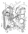
- FIG. 1 shows in side elevation a rear portion of a motorcycle equipped with a storage device according to a first embodiment of the present invention.
- a main frame 1 of the motorcycle is in the form of a single pipe with its rear end joined to the front side of a lower end 2a of a rear frame 2 which is of an inverted L shape as viewed in side elevation.
- the rear frame 2 comprises a front portion 2b inclined rearwardly from the lower end 2a to an upper position, a curved portion 2c contiguous to the upper end of the front portion 2b and positioned at the top of the L shape, and a rear portion 2d extending slightly upwardly from the curved portion 2c but substantially rearwardly horizontally.
- the rear frame 2 is constructed of a single tubular component in the form of a pipe or two joined pieces pressed from steel sheet.
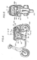
- the frames 1, 2 extend longitudinally of the motorcycle body in a substantially central area relative to the transverse direction of the motorcycle body, as shown in FIG. 2.
- a rear stay 3 of a U shape as viewed in plan has a pair of laterally spaced bars 3a having front ends 3b fastened by bolts 4 to the opposite sides of the rear frame 2 where the curved portion 2c and the rear portion 2d are joined to each other.
- a bracket 5 is mounted on the rear side of the lower end 2a of the rear frame 2, and a swingable power unit 8 comprising an engine 6 and a transmission case 7 has a front portion pivotally joined by a link 9 to the bracket 5.
- a rear wheel 100 is rotatably z mounted on a rear portion of the transmission case 7, which has a bracket 7a connected to the lower end of a rear cushioning unit 10 with its upper end coupled to the attachment bolt 4 fastened to the front end 3b of one of the bars 3a of the U-shaped rear stay 3.
- the rear cushioning unit 10 therefore supports the power unit 8 in a cantilevered fashion, and has its upper end supported, together with the front ends 3b of the rear stay 3, on the rear frame 2.
- the rear frame 2 doubles as a support post for a driver's seat 11 and for a storage device 30.
- the storage device 30 is disposed above the front portion 2b of the rear frame 2 and on the curved portion 2c and the rear portion 2d thereof, the storage device 30 opening upwardly.
- the storage device 30 is of substantially the same width as that of the seat 11 and has a longitudinal dimension rather smaller than that of the seat 11.
- the storage device 30 is in the form of a container which includes a surrounding side wall 31 having a front panel curved and reduced in width in complementary relation to the shape of the seat 11 as viewed in plan, and a rear panel extending laterally outwardly and increased in width.
- the storage device 30 has a bottom wall 34 including a front portion 35 displaced deeply downwardly and a rear portion 38 higher than the front portion 35. More specifically, the bottom wall 34 includes a first bulging portion 36 disposed centrally in the transverse direction of the bottom wall 34 and bulging upwardly from the front portion 35 to allow the curved portion 2c of the rear frame 2 to extend therein in the longitudinal direction, a pair of laterally spaced bottom portions 35 disposed one on each side of the bulging portion 36 and depending downwardly therefrom to a boundary area between the front and curved portions 2b, 2c of the rear frame 2, and a joint bottom portion 37 located at the lower end of the bulging portion 36 at the same level as the bottom portions 35 and interconnecting the front ends of the bottom portions 35 flatwise at the boundary area.
- the rear portion 38 of the bottom wall 34 has a second bulging portion 39 located at substantially the same level as the rear portion 2d of the rear frame 2 and bulging upwardly to allow an upper portion of the rear portion 2d to extend therein.
- the extent to which the second bulging portion 39 bulges upwardly is relatively small, so that the rear portion 38 is substantially flat in its entirety.
- the front portion 35 and rear portion 38 of the bottom wall 34 of the storage device 30 are joined to each other by means of a curved portion 40 behind which the bolt 4 connecting the upper end of the rear cushioning unit 10 to the rear frame 2 is positioned.
- the side wall 31 of the storage device 30 includes a rear wall panel 32 behind which there is disposed a substantially cubic auxiliary container 33 which is joined to the rear surface of the rear wall panel 32.
- the auxiliary container 33 opens upwardly and serves as a battery storage box with a battery 12 stored therein.
- the storage device 30 thus constructed can be installed on the rear frame 2 in the following manner.
- Attachment legs 41 extend downwardly from inner panel portions of the depending bottom portions 35, i.e., from outer panel portions of the central bulging portion 36.
- the attachment legs 41 are held in sandwiching relation to the upper end of the front frame portion 2b and fastened by bolts 42 to the lateral panels of the lower portion of the curved portion 2c of the rear frame 2.
- Attachment legs 43 project from the rear wall panel 32 laterally of the bulging portion 39 of the rear bottom wall portion 38.
- the attachment legs 43 are fastened to the rear portion 2d of the rear frame 2 by bolts 44 which are downwardly applied.
- the storage device 30 is thus installed astride the curved portion 2c and the rear portion 2d of the rear frame 2.
- a bracket 46a projects forwardly from an upper portion of a front wall panel 45 of the side wall 31.
- a bracket 46b on the front end of the seat 11 is pivotally joined to the bracket 46a by means of a pin 13.
- the brackets 46a, 46b and the pin 13 jointly constitute a hinge means.
- the bottom panel 11a of the seat 11 thus serves a cover for openably covering the upper opening of the storage device 30.
- the bottom panel 11a of the seat 11 extends rearwardly in overhanging relation to the auxiliary container 33 and a fuel tank 14 (described below).
- the fuel tank 14 is positioned behind the auxiliary container 33. As shown in FIG. 2, the fuel tank 12 has a lower portion surrounded by the rear stay 3. An oil tank 15 is positioned laterally of the auxiliary container 33 which is of a reduced width. As illustrated in FIG. 3, the oil tank 15 is of a shape extending downwardly from one side of the auxiliary container 33 and then inwardly around the bar 3a of the rear stay 3 below the bar 3a, thus achieving a required tank volume.
- the tanks 14, 15 have bottoms disposed over the top 16a of a rear fender 16.
- the rear frame 2, the storage device 30, the auxiliary container 33, and the tanks 14, 15 are laterally surrounded by a rear cover 17 on which a carrier 18 is mounted.
- the width of the storage device 30 may be the same as or larger than the width of the seat 11. Therefore, the storage space in the storage device 30 is large for high storage capability. For example, if a helmet A with a projecting sun visor is to be stored in the storage device 30 as shown in FIG. 1, the opposite depending pieces of the helmet are inserted toward the depending bottom portions 35 of the bottom wall 34 with the first bulging portion 36 projecting into the space in the helmet A, and the sun visor placed on the rear portion 38 of the bottom wall 34. The helmet A thus positioned is stably stored in the storage device 30.
- a storage device 300 for a motorcycle according to a second embodiment of the present invention will be described with reference to FIGS. 4 through 7.
- the storage device 300 is positioned on a rear frame 20 of the motorcycle which is illustrated as a scooter, the rear frame 20 being inclined rearwardly from a lower position to an upper position within a rear cover 118 of the motorcycle.
- a U-shaped stay 102 extending laterally is mounted on a front end of a rear portion 20e of the rear frame 20.
- the stay 102 has a pair of bars projecting laterally from the rear frame portion 20e and having two upstanding arms 102a with their upper ends bent outwardly away from each other.
- the bent upper ends of the upstanding arms 102a are positioned over and held in engagement with the upper edges of side members 118a of the rear cover 118.
- the rear cover 118 defines a space S opening upwardly and disposed below a driver's seat 11.
- a fuel tank 114 is disposed in a rear portion of the rear cover 118 and has a shape including a portion extending downwardly on one side of the rear portion of the rear frame 20.
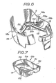
- a shallow container unit 130 as shown in FIG. 7 is disposed in the space S.
- the container unit 130 has a bottom wall 134 including an upwardly bulging portion 136 positioned centrally in the transverse direction of the container unit 130 and fitting complementarily over the rear frame 20.
- the container unit 130 also has a pair of laterally spaced side walls 131 having respective recessed portions 132 extending vertically and displaced transversely toward each other into the container unit 130. The recessed portions 132 are fitted respectively over the upstanding arms 102a of the stay 102.
- the container unit 130 is disposed in the space S which is defined by the rear frame 20, the stay 102, and the side members 118a and the rear wall 118b of the rear cover 118.
- the container unit 130 may be a molded component shaped complementarily to a configuration composed of the rear frame 20, the stay 102, and the side members 118a and the rear wall 118b of the rear cover 118.
- the rear cover 118 is composed of two separate bodies.
- the seat 11 is hinged to the rear frame 20 by brackets 113 projecting upwardly from the rear end of the rear frame 20 and brackets 11b projecting downwardly from the rear end of the bottom panel 11a of the seat 11, the brackets 113, 11b being pivotally joined by a bolt 103.
- the storage device 300 of the second embodiment includes a portion of the rear cover 118 and has a sufficient storage space for storing a helmet or other article.
- rear frame 20 in the second embodiment is shown as being a single component, it may be constructed of a plurality of joined pipes.
- the storage device disposed below the driver's seat which serves as the cover is not limited in width by the rear frame which extends centrally through the storage device. Therefore, the width of the storage device may be selected to cover the width of the motorcycle or the seat thereof.
- the depending bottom portions of the bottom wall of the storage device may be of a desired shape which is not affected by the rear frame, thereby allowing the storage device to have increased utility for storing objects therein.
- the depending bottom portions of the bottom wall of the storage device are positioned in dead spaces located on opposite sides of the rear space.
- the storage device of the embodiments is thus advantageous in effective utilization of the available space in the motorcycle.
- a helmet can be stably stored in the storage device because it is partly received in the depending bottom portions and on the rear portion of the rear frame.
Landscapes
- Engineering & Computer Science (AREA)
- Mechanical Engineering (AREA)
- Automatic Cycles, And Cycles In General (AREA)
Applications Claiming Priority (2)
| Application Number | Priority Date | Filing Date | Title |
|---|---|---|---|
| JP149298/86 | 1986-09-29 | ||
| JP1986149298U JPH0541988Y2 (de) | 1986-09-29 | 1986-09-29 |
Publications (3)
| Publication Number | Publication Date |
|---|---|
| EP0262912A2 true EP0262912A2 (de) | 1988-04-06 |
| EP0262912A3 EP0262912A3 (en) | 1988-08-03 |
| EP0262912B1 EP0262912B1 (de) | 1992-09-02 |
Family
ID=15472106
Family Applications (1)
| Application Number | Title | Priority Date | Filing Date |
|---|---|---|---|
| EP87308589A Expired - Lifetime EP0262912B1 (de) | 1986-09-29 | 1987-09-29 | Lagervorrichtung für Motorräder |
Country Status (6)
| Country | Link |
|---|---|
| US (1) | US4802682A (de) |
| EP (1) | EP0262912B1 (de) |
| JP (1) | JPH0541988Y2 (de) |
| KR (1) | KR880003803A (de) |
| DE (1) | DE3781492T2 (de) |
| IN (1) | IN169309B (de) |
Cited By (8)
| Publication number | Priority date | Publication date | Assignee | Title |
|---|---|---|---|---|
| FR2604967A1 (fr) * | 1986-10-14 | 1988-04-15 | Honda Motor Co Ltd | Vehicule du type scooter, muni d'un compartiment de rangement de grande capacite |
| FR2617791A1 (fr) * | 1987-07-06 | 1989-01-13 | Honda Motor Co Ltd | Motocyclette possedant dans sa carrosserie une boite de rangement pour un casque |
| EP0404194A1 (de) * | 1989-06-22 | 1990-12-27 | Yamaha Hatsudoki Kabushiki Kaisha | Ablageeinrichtung für Motorroller |
| US5048634A (en) * | 1987-07-21 | 1991-09-17 | Suzuki Jidosha Kogyo Kabushiki Kaisha | Motor bicycle |
| EP0603016A1 (de) * | 1992-12-18 | 1994-06-22 | Suzuki Kabushiki Kaisha | Gepäckträger für motorrollerartiges Fahrzeug |
| EP0726196A1 (de) * | 1995-02-07 | 1996-08-14 | Honda Giken Kogyo Kabushiki Kaisha | Sitzschienenstruktur eines motorrollerartigen Fahrzeuges |
| EP1950132A2 (de) | 2007-01-25 | 2008-07-30 | Yamaha Hatsudoki Kabushiki Kaisha | Fahrzeug |
| EP1772360A3 (de) * | 2005-10-07 | 2009-07-01 | Yamaha Hatsudoki Kabushiki Kaisha | Zweiradfahrzeug |
Families Citing this family (25)
| Publication number | Priority date | Publication date | Assignee | Title |
|---|---|---|---|---|
| DE3644645A1 (de) * | 1985-12-27 | 1987-08-27 | Honda Motor Co Ltd | Motorroller-fahrzeug |
| US5020625A (en) * | 1988-09-06 | 1991-06-04 | Suzuki Jidosha Kogyo Kabushiki Kaisha | Motor bicycle provided with article accommodating apparatus |
| JP2867534B2 (ja) * | 1990-01-29 | 1999-03-08 | スズキ株式会社 | 自動2輪車の収納ボックス |
| JPH0648342A (ja) * | 1992-07-31 | 1994-02-22 | Yamaha Motor Co Ltd | 自動二輪車の収納ボックス |
| US5664716A (en) * | 1996-02-22 | 1997-09-09 | Nuckolls; Glenn S. | Tank panel with removable pouch for motorcycles |
| JP4364341B2 (ja) * | 1999-03-31 | 2009-11-18 | 本田技研工業株式会社 | 自動二輪車における物品収納装置 |
| JP2001171580A (ja) * | 1999-12-17 | 2001-06-26 | Honda Motor Co Ltd | 自動二輪車のバッテリ配置構造 |
| JP3805606B2 (ja) * | 2000-07-12 | 2006-08-02 | 本田技研工業株式会社 | 自動二輪車 |
| US6659566B2 (en) | 2000-09-13 | 2003-12-09 | Bombardier Inc. | Cargo carrying compartments of an all terrain vehicle |
| US6533339B1 (en) * | 2000-10-11 | 2003-03-18 | Arctic Cat Inc. | ATV with fender storage compartment |
| US6663128B2 (en) * | 2001-06-08 | 2003-12-16 | Dichter Ben{Dot Over (Jamin Joseph | Magnetic tank pad |
| DE10262062B4 (de) * | 2002-04-30 | 2008-11-06 | Bayerische Motoren Werke Aktiengesellschaft | Öltank |
| US7137637B2 (en) * | 2002-11-15 | 2006-11-21 | Ackley Erick J | Wheel fender with integral tank |
| US7093856B2 (en) | 2003-03-13 | 2006-08-22 | Flexahopper Plastics Ltd. | Truck tank for accommodating a bed-mounted hitch |
| EP1555201A1 (de) * | 2004-01-19 | 2005-07-20 | Uwe Meyer | Elektroroller |
| TWI251568B (en) * | 2004-07-30 | 2006-03-21 | Kwang Yang Motor Co | Structure of storage box for all-terrain vehicle |
| US20060207028A1 (en) * | 2005-03-18 | 2006-09-21 | Richard Lombardo | Comfort pad for vehicles |
| US7278560B2 (en) * | 2005-05-23 | 2007-10-09 | Mathew Randolph Aron | Motorcycle saddlebag mounting system and apparatus |
| JP2007015641A (ja) * | 2005-07-11 | 2007-01-25 | Yamaha Motor Co Ltd | 電動自転車 |
| JP2010229840A (ja) * | 2009-03-26 | 2010-10-14 | Honda Motor Co Ltd | 自動二輪車 |
| US20100264183A1 (en) | 2009-04-15 | 2010-10-21 | Kaczowski Michael J | Motorcycle saddlebag |
| JP5914237B2 (ja) * | 2012-07-31 | 2016-05-11 | 本田技研工業株式会社 | 自動二輪車 |
| JP6133106B2 (ja) * | 2013-02-25 | 2017-05-24 | 本田技研工業株式会社 | 鞍乗り型車両のリザーブタンク給水構造 |
| KR20160102825A (ko) | 2015-02-23 | 2016-08-31 | 콘티넨탈 오토모티브 일렉트로닉스 유한회사 | 통합 케이블용 시일몰드 분기구조 및 그 제조방법 |
| US10717487B2 (en) | 2017-05-23 | 2020-07-21 | Gogoro Inc. | Fender assembly and vehicle including thereof |
Family Cites Families (29)
| Publication number | Priority date | Publication date | Assignee | Title |
|---|---|---|---|---|
| CA513935A (en) * | 1955-06-21 | General Motors Corporation | Closure weather strip | |
| BE556184A (de) * | ||||
| US2225914A (en) * | 1938-04-19 | 1940-12-24 | Salsbury Corp | Motor vehicle |
| GB830467A (en) * | 1955-06-13 | 1960-03-16 | Harry Holt | Improvements relating to motor-cycles |
| GB800488A (en) * | 1956-01-20 | 1958-08-27 | Nsu Werke Ag | A motor scooter |
| GB819690A (en) * | 1956-03-30 | 1959-09-09 | Innocenti Soc Generale | Improvements in or relating to motor-cycles |
| JPS4938851Y2 (de) * | 1971-03-22 | 1974-10-24 | ||
| US3788532A (en) * | 1972-06-22 | 1974-01-29 | R Bish | Saddlebag-travel case for a motorcycle |
| US3882951A (en) * | 1973-01-22 | 1975-05-13 | Hallamore Inc | Quiet slide out engine vehicle |
| GB1537233A (en) * | 1975-12-17 | 1978-12-29 | Bothwell P | Two-wheeled vehicles |
| JPS5551602A (en) * | 1978-10-13 | 1980-04-15 | Honda Motor Co Ltd | Front wheel suspension of travelling vehicle |
| US4265332A (en) * | 1979-06-21 | 1981-05-05 | Fmc Corporation | Heat extracting muffler system |
| US4577719A (en) * | 1979-06-29 | 1986-03-25 | Yamaha Hatsudoki Kabushiki Kaisha | Motorcycle fuel system with flow from a main tank through a lower auxiliary tank to its engine |
| JPS57140224A (en) * | 1981-02-25 | 1982-08-30 | Yamaha Motor Co Ltd | Autobicycle |
| US4441574A (en) * | 1981-05-21 | 1984-04-10 | Honda Giken Kogyo Kabushiki Kaisha | Rear cover device for motorcycles |
| US4487283A (en) * | 1981-10-19 | 1984-12-11 | Honda Motor Co., Ltd. | Motorcycle |
| JPS58126271A (ja) * | 1982-01-20 | 1983-07-27 | 本田技研工業株式会社 | 小型車両のトランク装置 |
| FR2519927B1 (fr) * | 1982-01-21 | 1985-06-28 | Honda Motor Co Ltd | Dispositif de coffre a bagages sur petits vehicules |
| JPS5950885A (ja) * | 1982-09-14 | 1984-03-24 | 本田技研工業株式会社 | 自動二輪車 |
| JPS5953281A (ja) * | 1982-09-20 | 1984-03-27 | 本田技研工業株式会社 | 自動二輪車 |
| JPS5963280A (ja) * | 1982-10-05 | 1984-04-10 | 本田技研工業株式会社 | 自動二輪車 |
| US4438877A (en) * | 1983-06-13 | 1984-03-27 | Jackson William S | Helmet restraining device |
| JPS6056629A (ja) * | 1983-09-06 | 1985-04-02 | Honda Motor Co Ltd | 自動二輪車 |
| JPH0662100B2 (ja) * | 1984-01-23 | 1994-08-17 | ヤマハ発動機株式会社 | スク−タ型車輛の物入れ装置 |
| JPH0653504B2 (ja) * | 1984-02-02 | 1994-07-20 | ヤマハ発動機株式会社 | 小型車両の荷物箱装置 |
| JPS61191486A (ja) * | 1985-02-20 | 1986-08-26 | ヤマハ発動機株式会社 | スク−タの収納装置 |
| US4637640A (en) * | 1985-02-27 | 1987-01-20 | Aeroquip Corporation | Push-in connect fitting |
| JPS61196187U (de) * | 1985-05-29 | 1986-12-06 | ||
| US4721178A (en) * | 1985-08-08 | 1988-01-26 | Honda Giken Kogyo Kabushiki Kaisha | Multi-wheeled vehicle |
-
1986
- 1986-09-29 JP JP1986149298U patent/JPH0541988Y2/ja not_active Expired - Lifetime
-
1987
- 1987-04-01 IN IN236/MAS/87A patent/IN169309B/en unknown
- 1987-08-25 US US07/089,159 patent/US4802682A/en not_active Expired - Fee Related
- 1987-09-03 KR KR870009757A patent/KR880003803A/ko not_active Withdrawn
- 1987-09-29 EP EP87308589A patent/EP0262912B1/de not_active Expired - Lifetime
- 1987-09-29 DE DE8787308589T patent/DE3781492T2/de not_active Expired - Fee Related
Cited By (12)
| Publication number | Priority date | Publication date | Assignee | Title |
|---|---|---|---|---|
| FR2604967A1 (fr) * | 1986-10-14 | 1988-04-15 | Honda Motor Co Ltd | Vehicule du type scooter, muni d'un compartiment de rangement de grande capacite |
| FR2617791A1 (fr) * | 1987-07-06 | 1989-01-13 | Honda Motor Co Ltd | Motocyclette possedant dans sa carrosserie une boite de rangement pour un casque |
| US5040632A (en) * | 1987-07-06 | 1991-08-20 | Honda Giken Kogyo Kabushiki Kaisha | Motorcycle |
| US5048634A (en) * | 1987-07-21 | 1991-09-17 | Suzuki Jidosha Kogyo Kabushiki Kaisha | Motor bicycle |
| EP0404194A1 (de) * | 1989-06-22 | 1990-12-27 | Yamaha Hatsudoki Kabushiki Kaisha | Ablageeinrichtung für Motorroller |
| EP0603016A1 (de) * | 1992-12-18 | 1994-06-22 | Suzuki Kabushiki Kaisha | Gepäckträger für motorrollerartiges Fahrzeug |
| US5465882A (en) * | 1992-12-18 | 1995-11-14 | Suzuki Kabushiki Kaisha | Carrier for scooter-type vehicle |
| EP0726196A1 (de) * | 1995-02-07 | 1996-08-14 | Honda Giken Kogyo Kabushiki Kaisha | Sitzschienenstruktur eines motorrollerartigen Fahrzeuges |
| CN1072579C (zh) * | 1995-02-07 | 2001-10-10 | 本田技研工业株式会社 | 轻型摩托车的车座轨道结构 |
| EP1772360A3 (de) * | 2005-10-07 | 2009-07-01 | Yamaha Hatsudoki Kabushiki Kaisha | Zweiradfahrzeug |
| EP1950132A2 (de) | 2007-01-25 | 2008-07-30 | Yamaha Hatsudoki Kabushiki Kaisha | Fahrzeug |
| EP1950132A3 (de) * | 2007-01-25 | 2010-03-10 | Yamaha Hatsudoki Kabushiki Kaisha | Fahrzeug |
Also Published As
| Publication number | Publication date |
|---|---|
| EP0262912B1 (de) | 1992-09-02 |
| JPS6353890U (de) | 1988-04-11 |
| IN169309B (de) | 1991-09-28 |
| DE3781492D1 (de) | 1992-10-08 |
| DE3781492T2 (de) | 1993-01-07 |
| EP0262912A3 (en) | 1988-08-03 |
| JPH0541988Y2 (de) | 1993-10-22 |
| KR880003803A (ko) | 1988-05-30 |
| US4802682A (en) | 1989-02-07 |
Similar Documents
| Publication | Publication Date | Title |
|---|---|---|
| EP0262912A2 (de) | Lagervorrichtung für Motorräder | |
| US20020008397A1 (en) | Article storage device of motorcycle | |
| US6651767B2 (en) | Container box structure in two-wheeled motor vehicle | |
| JPH0455181A (ja) | スクータ車両の物品収納装置 | |
| JPH06156344A (ja) | 自動二輪車の物品収納装置 | |
| CN101468679B (zh) | 机动两轮车的收纳箱结构 | |
| JP2883751B2 (ja) | 自動二輪車のラゲージボックス | |
| US4444856A (en) | Battery for vehicle | |
| JP3561342B2 (ja) | 自動二輪車における盗難防止用u字状ロック収納構造 | |
| JPH0561157B2 (de) | ||
| JP2972164B2 (ja) | スクータ型2輪車両 | |
| KR900008370Y1 (ko) | 자동 2륜차의 물품수납장치 | |
| JPH0727273Y2 (ja) | スクータ型車両 | |
| EP1125835B1 (de) | Gepäckbehälter für rollerartiges Fahrzeug | |
| JP3367760B2 (ja) | 車両の車体構造 | |
| JP2557808B2 (ja) | スクータ型車輌 | |
| JP2952492B2 (ja) | スクータ型自動二輪車の収納ボックス | |
| JP2532455B2 (ja) | 自動二輪車用物品収納装置 | |
| JPH0321578A (ja) | スクータ型自動二輪車 | |
| JP3335234B2 (ja) | スクータ型車両のオイルタンク装置 | |
| JPS6340392Y2 (de) | ||
| JPH05131963A (ja) | スクータ型車両 | |
| JP2732065B2 (ja) | 2輪スクータ型車両 | |
| CN2427423Y (zh) | 摩托车侧盖装置 | |
| JPH0627509Y2 (ja) | 自動二輪車の物入れ装置 |
Legal Events
| Date | Code | Title | Description |
|---|---|---|---|
| PUAI | Public reference made under article 153(3) epc to a published international application that has entered the european phase |
Free format text: ORIGINAL CODE: 0009012 |
|
| AK | Designated contracting states |
Kind code of ref document: A2 Designated state(s): DE FR GB IT |
|
| PUAL | Search report despatched |
Free format text: ORIGINAL CODE: 0009013 |
|
| AK | Designated contracting states |
Kind code of ref document: A3 Designated state(s): DE FR GB IT |
|
| 17P | Request for examination filed |
Effective date: 19881222 |
|
| 17Q | First examination report despatched |
Effective date: 19891212 |
|
| GRAA | (expected) grant |
Free format text: ORIGINAL CODE: 0009210 |
|
| AK | Designated contracting states |
Kind code of ref document: B1 Designated state(s): DE FR GB IT |
|
| REF | Corresponds to: |
Ref document number: 3781492 Country of ref document: DE Date of ref document: 19921008 |
|
| ET | Fr: translation filed | ||
| ITF | It: translation for a ep patent filed | ||
| PLBE | No opposition filed within time limit |
Free format text: ORIGINAL CODE: 0009261 |
|
| STAA | Information on the status of an ep patent application or granted ep patent |
Free format text: STATUS: NO OPPOSITION FILED WITHIN TIME LIMIT |
|
| 26N | No opposition filed | ||
| PGFP | Annual fee paid to national office [announced via postgrant information from national office to epo] |
Ref country code: GB Payment date: 19940923 Year of fee payment: 8 |
|
| PGFP | Annual fee paid to national office [announced via postgrant information from national office to epo] |
Ref country code: DE Payment date: 19940929 Year of fee payment: 8 |
|
| ITTA | It: last paid annual fee | ||
| PG25 | Lapsed in a contracting state [announced via postgrant information from national office to epo] |
Ref country code: GB Effective date: 19950929 |
|
| GBPC | Gb: european patent ceased through non-payment of renewal fee |
Effective date: 19950929 |
|
| PG25 | Lapsed in a contracting state [announced via postgrant information from national office to epo] |
Ref country code: DE Effective date: 19960601 |
|
| PGFP | Annual fee paid to national office [announced via postgrant information from national office to epo] |
Ref country code: FR Payment date: 19970917 Year of fee payment: 11 |
|
| PG25 | Lapsed in a contracting state [announced via postgrant information from national office to epo] |
Ref country code: FR Free format text: LAPSE BECAUSE OF NON-PAYMENT OF DUE FEES Effective date: 19990531 |
|
| REG | Reference to a national code |
Ref country code: FR Ref legal event code: ST |
|
| PG25 | Lapsed in a contracting state [announced via postgrant information from national office to epo] |
Ref country code: IT Free format text: LAPSE BECAUSE OF NON-PAYMENT OF DUE FEES;WARNING: LAPSES OF ITALIAN PATENTS WITH EFFECTIVE DATE BEFORE 2007 MAY HAVE OCCURRED AT ANY TIME BEFORE 2007. THE CORRECT EFFECTIVE DATE MAY BE DIFFERENT FROM THE ONE RECORDED. Effective date: 20050929 |