EP0263310A2 - Montage des patins d'une chenille de traction pour véhicule - Google Patents
Montage des patins d'une chenille de traction pour véhicule Download PDFInfo
- Publication number
- EP0263310A2 EP0263310A2 EP87113074A EP87113074A EP0263310A2 EP 0263310 A2 EP0263310 A2 EP 0263310A2 EP 87113074 A EP87113074 A EP 87113074A EP 87113074 A EP87113074 A EP 87113074A EP 0263310 A2 EP0263310 A2 EP 0263310A2
- Authority
- EP
- European Patent Office
- Prior art keywords
- belt
- cleat assembly
- plate
- grouser
- projections
- Prior art date
- Legal status (The legal status is an assumption and is not a legal conclusion. Google has not performed a legal analysis and makes no representation as to the accuracy of the status listed.)
- Granted
Links
Images

Classifications
-
- B—PERFORMING OPERATIONS; TRANSPORTING
- B62—LAND VEHICLES FOR TRAVELLING OTHERWISE THAN ON RAILS
- B62D—MOTOR VEHICLES; TRAILERS
- B62D55/00—Endless track vehicles
- B62D55/08—Endless track units; Parts thereof
- B62D55/18—Tracks
- B62D55/20—Tracks of articulated type, e.g. chains
- B62D55/202—Wheel engaging parts; Wheel guides on links
-
- B—PERFORMING OPERATIONS; TRANSPORTING
- B62—LAND VEHICLES FOR TRAVELLING OTHERWISE THAN ON RAILS
- B62D—MOTOR VEHICLES; TRAILERS
- B62D55/00—Endless track vehicles
- B62D55/08—Endless track units; Parts thereof
- B62D55/18—Tracks
- B62D55/26—Ground engaging parts or elements
- B62D55/28—Ground engaging parts or elements detachable
- B62D55/286—For soft grounds, e.g. consisting of snow or swamp
Definitions
- the field of the invention is endless track assemblies for snow grooming vehicles, and more particularly the cleat assemblies thereof, including structures for fastening the cleats to the flexible plastic belting of such tracks.
- Snow groomer vehicles use endless tracks having flexible plastic belts made endless by connecting the ends with lacing or the like.
- the belts are often reinforced by plies of fabric incorporated into the rubber-like belt material.
- Steel cleats are bolted across the belts at intervals of a few inches.
- Each belt is engaged by a power-transmitting sprocket wheel, which forces the belt to travel around a set of guiding wheels call bogies.
- the powered belt imparts horizontal shear force to the cleats, which engages the snow to propel the vehicle.
- cleat constructions are disclosed in U.S. Patent Nos. 3,765,731, 4,560,211, 4,281,882 and 4,059,315.
- the ground contacting cleat also called a grouser, is fastened to the outside of the flexible belting by bolts or rivets installed in matching holes in the cleat, belt, and a metal backing plate on the inside of the belt.
- the shanks of the bolts bear against a side of the holes in the belt to transfer the shearing force to the cleats, perhaps initially aided by friction between the belt and the cleat and backing plate.
- the belt material is malleable, and the fabric plies are discontinuous at the holes, so that the holes become permanently elongated by the concentrated stresses, loosening the cleats.
- the hole elongation occurs even with great clamping force between the cleat and the backing plate. This is because the belting material creeps under prolonged stress to relieve the claming force and substantially eliminating the initally helpful friction between the belt and the cleats and backing plate.
- a cleat assembly comprising an elongate, ground engaging grouser plate and a belt backing plate, both having aligned sets of spaced mounting bores, the belt side of at least one but preferably both plates having a multiplicity of projections on the sides toward the belt.
- Bolt and nut assemblies installed in the mounting holes forcibly press the projections into the belt.
- the shearing force is distributed among the many projections, lessening the local unit stresses upon the belt and its reinforcing fabric.
- the reinforcing fabric remains unbroken at the projections, directly accepting the shear loads.
- the shear loads must in state of the art cleat assemblies be first transferred by the bolts bearing upon the locally unreinforced plastic material of the belt at each hole.
- the stresses upon the mounting holes in the belt are greatly relieved in the present design, in fact probably eliminated after the belt material yields with passage of time.
- the projections pressed into the belt provide many times the effective shear resisting area than do the bolt shanks.
- the plastic material of the belt creeps plastically with the prolonged clamping stress, it tends to set about the projections, providing continued close contact, so that the cleat remains tightly secured.
- the grouser plates may be without projections, which are instead provided upon a separate gripper plate installed between the grouser and the belt.
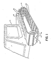
- FIG. 1 An endless belt track assembly, with a cleat assembly 10 in accordance with the invention, is shown in FIG. 1 installed upon an off-road vehicle 11, fragmentally indicated.
- Vehicle 11 may be a snow groomer for use in ski areas, for example.
- the track assembly 12 comprises a flexible endless belt 13 of soft plastic, made endless by lacing its ends together.
- the cleat assemblies 10 are secured crosswise to the belt 13 at invervals.
- Track 12 is supported upon the vehicle by wheels 14, one of which may for power purposes be connected to the engine of vehicle 11.
- the ground engaging members 15 of cleat assemblies 10, interchangeably called cleats or grousers are constructed in many configurations, each calculated to provide improved traction with the snow, to prevent side slip of the vehicle, or otherwise perform more desirably and efficiently.
- the present invention is not concerned with traction developing qualities, but with methods for fastening the grousers 15 to the belt 13 in permenently tight condition.
- Belt 13 is constructed of rubber-like plastic material, sometimes called synthetic rubber, of which neoprene, butyl rubber and nitrile rubber are examples.
- synthetic rubber for belts used on lightweight vehicles such as snowmobiles, such plastic material is at times utilized without reinforcement. See U.S. Patent No. 4,059,315
- the belt material is more commonly reinforced by multiple non-elastic fabric plies incorporated into the belt structure.
- the fabric plies strengthen the belt and enable it to withstand high tension forces without excessive stretching.
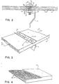
- a fragment of belting material having four embedded plastic plies 26 is shown in FIG. 4.
- the plies have non-elastic polyester threads longitudinal to the belt, but very elastic nonabrasive nylon cross threads.
- the material of belt 13 is elastic in the short term, but deforms plastically under prolonged stress. Both characteristics create difficulties in securing the cleat assembly 10 to the belt so that it will not loosen.
- the elastic give acts against developing the high clamping forces needed to develop significant shear resisting friction on the surface of the belt.
- the plastic give under prolonged stress exacerbates the situation by tending to relieve the clamping forces, destroying whatever friction has been successfully developed initially.
- FIG. 2 A state of the art track assembly is illustrated in FIG. 2.
- the cleat assembly is secured to belt 13 by bolt assemblies 16 installed in aligned holes 17, 18 and 19 in the grouser plate 15, belt 13 and a metallic backing plate 20 respectively.
- the belt contacting surfaces 21 and 22 of grouser 15 and plate 20 respectively are typically flat and smooth.
- Belt 13 is squeezed between grouser plate 15 and backing plate 20 by the bolt assembly 16. Either initially or with passage of time, the friction developed upon surface 21 and 22 may be insufficient to resist the shear load between belt 13 and the cleat assembly. The shear must then be resisted by bearing of bolt shanks 24 against sides 23 of the belt mounting holes 18.
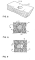
- FIG. 5 illustrates a fragment of belt 13 after an extended period of us.
- FIG. 6 shows the plies 26 severed to provide the holes 18, and FIG. 7 the distorted holes 18 and plies 26.
- the holes 18 are deformed by the shearing forces until the uncut elastic cross threads near the holes can pick up the bearing forces from the holes and transform them into tension forces in the belt.
- the concentrated bearing forces elongate the unsupported holes 18, permanently deforming the belt 13 at the holes and loosening the cleat assemblies.
- Manuevering the vehicle forwardly and backwardly alternates the direction of the forces on the holes 18, deforming them both forwardly and rearwardly.
- the cleat assembly 10 of the present invention does not rely upon transfer of the forces; through the bolts 25 to the belt 13 at the holes 18. Rather, it provides for transfer of the shearing forces into the belt remotely from the mounting holes.
- Cleat assembly 10 comprises a cleat backing plate 20 having a large number of projections 27 on its belt side face, created by forcibly dimpling its opposite face.
- Grouser plate 15 has similar beltward projections 28. Projections 27 and 28 are preferably equally spaced along plate 20 and grouser 15, advantageously in two rows. (FIG. 3) When bolt assemblies 16 are tightened, dimple projections 27 and 28 are pressed to seat firmly into the opposite surfaces of belt 13. Their projecting surfaces 29 provide bearing area to resist the shearing loads.
- the surfaces 29 in total provide a very large bearing area, distributing the loads to reduce local stresses in the belt so that it is not deformed excessively. Since the fabric layers 26 are not severed in the dimple locations, the shearing forces are picked up and tensioned by the fabric plies 26 at each projection with minimal local belt distortion. The local squeeze of the belt at each dimple enhances the bond between the rubber and the fabric assuring transfer of the shearing load into the belt more reliably.
- the holes 18 are distorted only minimally, because the seated projections 27 and 28 move very little upon the belt, so that the holes assume almost none of the load. The grip of plates 15 and 22 upon the belt tends to decrease as the plastic material sets under the sustained clamping forces.
- FIG. 9 illustrates a fragment of the belt 13 after extended services, with the cleat assembly 10 removed.
- the belt 13 is thinned somewhat where it has been clamped between the backing plate 22 and the grouser 15.
- Craters 30 conform to the dimple projections 27 and 28. Note that the belt mounting hole 18 is undistorted.
- FIG. 10 shows another preferred embodiment of cleat assembly 10, wherein the grouser 15 and backing plate 20 have spikes-like projections 27 and 28, instead of the previously described dimple projections.
- the plastic material of belt 13 is damaged somewhat, being pierced by the spikes 27 and 28.
- the spikes extend into belt 13 sufficiently to directly engage the fabric plies 26. The shearing forces may then be immediately resisted by tension in the fabric 26 As with the dimple projections, the spikes also provide projecting bearing area for shear force resistance.
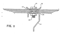
- FIG. 11 Still another preferred embodiment of cleat assembly 10 is shown in FIG. 11, employing punch-formed tab projections 27 and 28.
- the tabs are, as with the dimples, pressed into the material of belt 13.
- the projecting tabs perform in substantially the same manner as do the dimple projections. Local cutting of the material of belt 13 by the tab edges may occur, but may be acceptable providing the fabric 28 is not severed. Care in manufacturing is advisable to avoid sharp cutting edges and corners.
- cleat 10 Other possible embodiments of cleat 10, not illustrated, include the use of continuous corrugations, machined knurls, or other types of projections for the grouser 15 and backing plate however, the projections, to be sufficiently effective must be substantial. Merely roughening the surfaces 21 and 22 would not provide significant benefits.
- the projections 28 may be located in other patterns than those illustrated. Especially, the grouser and backing plate projection patterns need not be limited to the matching patterns indicated in certain of the illustrations.
Landscapes
- Engineering & Computer Science (AREA)
- Chemical & Material Sciences (AREA)
- Combustion & Propulsion (AREA)
- Transportation (AREA)
- Mechanical Engineering (AREA)
- Escalators And Moving Walkways (AREA)
- Belt Conveyors (AREA)
- Automotive Seat Belt Assembly (AREA)
- Devices For Conveying Motion By Means Of Endless Flexible Members (AREA)
- Automobile Manufacture Line, Endless Track Vehicle, Trailer (AREA)
Priority Applications (1)
| Application Number | Priority Date | Filing Date | Title |
|---|---|---|---|
| AT87113074T ATE63509T1 (de) | 1986-09-08 | 1987-09-08 | Zusammenbau der greifer in einer fahrzeugantriebsraupe. |
Applications Claiming Priority (2)
| Application Number | Priority Date | Filing Date | Title |
|---|---|---|---|
| US06/904,635 US5033801A (en) | 1986-09-08 | 1986-09-08 | Cleat assembly for endless track vehicle |
| US904635 | 1986-09-08 |
Publications (3)
| Publication Number | Publication Date |
|---|---|
| EP0263310A2 true EP0263310A2 (fr) | 1988-04-13 |
| EP0263310A3 EP0263310A3 (en) | 1988-06-08 |
| EP0263310B1 EP0263310B1 (fr) | 1991-05-15 |
Family
ID=25419482
Family Applications (1)
| Application Number | Title | Priority Date | Filing Date |
|---|---|---|---|
| EP87113074A Expired - Lifetime EP0263310B1 (fr) | 1986-09-08 | 1987-09-08 | Montage des patins d'une chenille de traction pour véhicule |
Country Status (4)
| Country | Link |
|---|---|
| US (1) | US5033801A (fr) |
| EP (1) | EP0263310B1 (fr) |
| AT (1) | ATE63509T1 (fr) |
| DE (1) | DE3770105D1 (fr) |
Cited By (3)
| Publication number | Priority date | Publication date | Assignee | Title |
|---|---|---|---|---|
| IT201600068841A1 (it) * | 2016-07-01 | 2018-01-01 | Prinoth Spa | Cinghia per veicoli cingolati |
| CN108016519A (zh) * | 2017-12-20 | 2018-05-11 | 佛山科学技术学院 | 一种履带行进装置 |
| EP3939867A1 (fr) * | 2020-07-13 | 2022-01-19 | Kässbohrer Geländefahrzeug AG | Chenilles d'entraînement pour un véhicule à chenilles |
Families Citing this family (18)
| Publication number | Priority date | Publication date | Assignee | Title |
|---|---|---|---|---|
| US5265949A (en) * | 1989-08-21 | 1993-11-30 | Kassbohrer Karl Fahrzeugwerke Gmbh | Steel crosspiece |
| US5401088A (en) * | 1991-06-28 | 1995-03-28 | Rubel; Edward R. | Traction assembly for a flexible track |
| US5199771A (en) * | 1992-03-02 | 1993-04-06 | Logan Manufacturing Company | Not retaining cleat for vehicle endless track |
| US5299860A (en) * | 1992-05-07 | 1994-04-05 | Anderson Lynn J | Snowmobile stud fastener |
| US5542753A (en) * | 1994-01-27 | 1996-08-06 | Plumer; Mark J. | Wheel opening inserts and lug nut assemblies thereof for mounting non-ferrous vehicle wheels |
| US5533796A (en) * | 1994-08-15 | 1996-07-09 | Lmc Operating Corp. | Belt construction for vehicle endless track |
| US5573316A (en) * | 1995-06-02 | 1996-11-12 | Wankowski; Russell A. | Lightweight snowmobile traction stud |
| US5685621A (en) * | 1996-09-11 | 1997-11-11 | Nugent; David Scott | Snowmobile stud with replaceable tip |
| US5980001A (en) * | 1997-03-07 | 1999-11-09 | Rubel; Edward R | Ground penetrating traction stud |
| DE29913344U1 (de) * | 1999-07-30 | 2000-12-07 | Kässbohrer Geländefahrzeug AG, 89250 Senden | Kettensteg für Laufketten |
| CA2289805C (fr) * | 1999-11-16 | 2006-10-17 | Denis Courtemanche | Courroie porteuse pour motoneiges avec pinces de transfert de chaleur |
| US6609772B2 (en) | 2001-07-09 | 2003-08-26 | International Engineering And Manufacturing, Inc. | Traction stud force distributing backer member |
| US7712846B2 (en) * | 2003-02-24 | 2010-05-11 | Arctic Cat Inc. | Snowmobile drive track |
| CA2458321C (fr) * | 2003-02-24 | 2013-08-06 | Arctic Cat Inc. | Chenille de motoneige |
| US8672064B2 (en) * | 2007-09-07 | 2014-03-18 | Loegering Mfg. Inc. | Apparatus for converting a wheeled vehicle to a tracked vehicle |
| CA2881247C (fr) * | 2015-02-04 | 2021-04-20 | Brad Blackburn | Mecanisme de traction amovible pour vehicules a chenille |
| DE202018104420U1 (de) * | 2018-07-31 | 2018-08-22 | Hans Hall Gmbh | Vorrichtung zum Befestigen eines Raupenkettenorgans einer Raupenkette an einem Raupenband der Raupenkette |
| US12280840B2 (en) * | 2019-11-15 | 2025-04-22 | John Paul Blanchard | Grouser traction cleat that cinches onto rubber continuous tracks |
Family Cites Families (17)
| Publication number | Priority date | Publication date | Assignee | Title |
|---|---|---|---|---|
| DE481836C (de) * | 1929-09-03 | Heinrich Ernst Kniepkamp Dipl | Anordnung der durch Drahtseile miteinander verbundenen, an dem Laufband fuer Kraftfahrzeuge mittels Schraubenbolzen befestigten Antriebs- und Fuehrungsglieder | |
| DE737703C (de) * | 1937-11-04 | 1943-10-19 | Carl F W Borgward | Laufband fuer Kraftfahrzeuge |
| US2823080A (en) * | 1955-06-22 | 1958-02-11 | Poor & Co | Tractor rail and grouser plate assembly |
| US3165364A (en) * | 1961-03-01 | 1965-01-12 | Utah Scient Res Foundation | Smooth-riding self-cleaning endless track |
| US3346306A (en) * | 1964-11-16 | 1967-10-10 | Go Tract Ltd | Track element for a track-laying vehicle |
| US3582154A (en) * | 1968-06-03 | 1971-06-01 | Gates Rubber Co | Endless track for multiterrain vehicles |
| US3572851A (en) * | 1969-01-27 | 1971-03-30 | Paul W Schuler | Snowmobile track cleat stud |
| US3765731A (en) * | 1971-10-08 | 1973-10-16 | Norman W Lund | Traction cleat and drive belt with such attached |
| US3782787A (en) * | 1972-01-10 | 1974-01-01 | E Rubel | Traction stud assembly for snowmobiles |
| US3838894A (en) * | 1972-12-26 | 1974-10-01 | Special Sports Prod Corp | Endless drive track for snowmobiles and the like |
| US3973808A (en) * | 1974-12-12 | 1976-08-10 | James R. Musselman | Ice stud for snowmobile tracks |
| CA1020990A (fr) * | 1975-02-14 | 1977-11-15 | Bombardier Limited | Patin a agrafes pour chenille de motoneige |
| US3958839A (en) * | 1975-02-18 | 1976-05-25 | Foremost International Industries Ltd. | Segmented track |
| US4059315A (en) * | 1976-01-02 | 1977-11-22 | Jolliffe James D | Cleat anchor for flexible vehicle track |
| US4281882A (en) * | 1977-04-15 | 1981-08-04 | Lely Cornelis V D | Vehicle track with I-shaped ground engaging profiles |
| NL7707261A (nl) * | 1977-06-30 | 1979-01-03 | Texas Industries Inc | Flexibele rupsband. |
| DE3533933A1 (de) * | 1985-09-24 | 1987-03-26 | Jaeger Arnold | Lauf- oder foerderband mit mitnehmern |
-
1986
- 1986-09-08 US US06/904,635 patent/US5033801A/en not_active Expired - Fee Related
-
1987
- 1987-09-08 DE DE8787113074T patent/DE3770105D1/de not_active Expired - Fee Related
- 1987-09-08 AT AT87113074T patent/ATE63509T1/de not_active IP Right Cessation
- 1987-09-08 EP EP87113074A patent/EP0263310B1/fr not_active Expired - Lifetime
Cited By (6)
| Publication number | Priority date | Publication date | Assignee | Title |
|---|---|---|---|---|
| IT201600068841A1 (it) * | 2016-07-01 | 2018-01-01 | Prinoth Spa | Cinghia per veicoli cingolati |
| WO2018002903A1 (fr) * | 2016-07-01 | 2018-01-04 | Prinoth S.P.A. | Courroie pour véhicules à chenilles |
| US11338870B2 (en) | 2016-07-01 | 2022-05-24 | Prinoth S.P.A. | Belt for tracked vehicles |
| CN108016519A (zh) * | 2017-12-20 | 2018-05-11 | 佛山科学技术学院 | 一种履带行进装置 |
| CN108016519B (zh) * | 2017-12-20 | 2023-07-14 | 佛山科学技术学院 | 一种履带行进装置 |
| EP3939867A1 (fr) * | 2020-07-13 | 2022-01-19 | Kässbohrer Geländefahrzeug AG | Chenilles d'entraînement pour un véhicule à chenilles |
Also Published As
| Publication number | Publication date |
|---|---|
| US5033801A (en) | 1991-07-23 |
| ATE63509T1 (de) | 1991-06-15 |
| EP0263310A3 (en) | 1988-06-08 |
| EP0263310B1 (fr) | 1991-05-15 |
| DE3770105D1 (de) | 1991-06-20 |
Similar Documents
| Publication | Publication Date | Title |
|---|---|---|
| US5033801A (en) | Cleat assembly for endless track vehicle | |
| US5354124A (en) | Water sealed, cable reinforced vehicle endless track and cleat assembly | |
| US5199771A (en) | Not retaining cleat for vehicle endless track | |
| US4059315A (en) | Cleat anchor for flexible vehicle track | |
| US7377601B2 (en) | Detachable crawler | |
| US5299860A (en) | Snowmobile stud fastener | |
| US5466056A (en) | Cleat retaining assembly for vehicle endless track | |
| US5533796A (en) | Belt construction for vehicle endless track | |
| CA1315837C (fr) | Assemblage de joint pour une bande d'entrainement sans fin | |
| US7156473B2 (en) | Elastic track shoe | |
| EP2086822A1 (fr) | Ensemble chaîne de traction pour chenilles élastomères | |
| US6213573B1 (en) | Rubber pads | |
| EP0091817B1 (fr) | Maillon de chenille avec tampon de roulement | |
| US20030184157A1 (en) | Grouser assembly | |
| US5201574A (en) | Cleat retaining bolt and nut for vehicle endless track | |
| US4027925A (en) | Detachable road protecting device for tracked vehicles | |
| WO1995032885A1 (fr) | Plaque de chenille en materiau elastique et bande de chenille | |
| CA1316971C (fr) | Crampons pour vehicules a chenilles | |
| WO2001087693A1 (fr) | Engin a chenilles en caoutchouc | |
| US4844562A (en) | Track for tracked vehicle, E.G. a ski-trail packer | |
| JP3354684B2 (ja) | クローラ用弾性履帯 | |
| JPH04106208A (ja) | 防舷材の受衝パッド取付け構造 | |
| JPH0848269A (ja) | 弾性体履板及び無限軌道履帯 | |
| JPH09301233A (ja) | 鉄クローラのゴムパッド取付構造 | |
| JP2000085641A (ja) | クローラ走行装置 |
Legal Events
| Date | Code | Title | Description |
|---|---|---|---|
| PUAI | Public reference made under article 153(3) epc to a published international application that has entered the european phase |
Free format text: ORIGINAL CODE: 0009012 |
|
| AK | Designated contracting states |
Kind code of ref document: A2 Designated state(s): AT CH DE FR IT LI |
|
| PUAL | Search report despatched |
Free format text: ORIGINAL CODE: 0009013 |
|
| AK | Designated contracting states |
Kind code of ref document: A3 Designated state(s): AT CH DE FR IT LI |
|
| 17P | Request for examination filed |
Effective date: 19880721 |
|
| 17Q | First examination report despatched |
Effective date: 19881212 |
|
| GRAA | (expected) grant |
Free format text: ORIGINAL CODE: 0009210 |
|
| AK | Designated contracting states |
Kind code of ref document: B1 Designated state(s): AT CH DE FR IT LI |
|
| REF | Corresponds to: |
Ref document number: 63509 Country of ref document: AT Date of ref document: 19910615 Kind code of ref document: T |
|
| REF | Corresponds to: |
Ref document number: 3770105 Country of ref document: DE Date of ref document: 19910620 |
|
| ET | Fr: translation filed | ||
| ITF | It: translation for a ep patent filed | ||
| PLBE | No opposition filed within time limit |
Free format text: ORIGINAL CODE: 0009261 |
|
| STAA | Information on the status of an ep patent application or granted ep patent |
Free format text: STATUS: NO OPPOSITION FILED WITHIN TIME LIMIT |
|
| 26N | No opposition filed | ||
| PGFP | Annual fee paid to national office [announced via postgrant information from national office to epo] |
Ref country code: CH Payment date: 19940914 Year of fee payment: 8 |
|
| PGFP | Annual fee paid to national office [announced via postgrant information from national office to epo] |
Ref country code: FR Payment date: 19940919 Year of fee payment: 8 |
|
| PGFP | Annual fee paid to national office [announced via postgrant information from national office to epo] |
Ref country code: AT Payment date: 19940921 Year of fee payment: 8 |
|
| PGFP | Annual fee paid to national office [announced via postgrant information from national office to epo] |
Ref country code: DE Payment date: 19941025 Year of fee payment: 8 |
|
| PG25 | Lapsed in a contracting state [announced via postgrant information from national office to epo] |
Ref country code: AT Effective date: 19950908 |
|
| PG25 | Lapsed in a contracting state [announced via postgrant information from national office to epo] |
Ref country code: LI Effective date: 19950930 Ref country code: CH Effective date: 19950930 |
|
| REG | Reference to a national code |
Ref country code: CH Ref legal event code: PL |
|
| PG25 | Lapsed in a contracting state [announced via postgrant information from national office to epo] |
Ref country code: FR Effective date: 19960531 |
|
| PG25 | Lapsed in a contracting state [announced via postgrant information from national office to epo] |
Ref country code: DE Effective date: 19960601 |
|
| REG | Reference to a national code |
Ref country code: FR Ref legal event code: ST |
|
| PG25 | Lapsed in a contracting state [announced via postgrant information from national office to epo] |
Ref country code: IT Free format text: LAPSE BECAUSE OF NON-PAYMENT OF DUE FEES;WARNING: LAPSES OF ITALIAN PATENTS WITH EFFECTIVE DATE BEFORE 2007 MAY HAVE OCCURRED AT ANY TIME BEFORE 2007. THE CORRECT EFFECTIVE DATE MAY BE DIFFERENT FROM THE ONE RECORDED. Effective date: 20050908 |