EP0263392A2 - Tissu tétra-axial et métier à tisser des tissus triaxiaux - Google Patents
Tissu tétra-axial et métier à tisser des tissus triaxiaux Download PDFInfo
- Publication number
- EP0263392A2 EP0263392A2 EP87114141A EP87114141A EP0263392A2 EP 0263392 A2 EP0263392 A2 EP 0263392A2 EP 87114141 A EP87114141 A EP 87114141A EP 87114141 A EP87114141 A EP 87114141A EP 0263392 A2 EP0263392 A2 EP 0263392A2
- Authority
- EP
- European Patent Office
- Prior art keywords
- bias
- yarn
- yarns
- tetraaxial
- warp
- Prior art date
- Legal status (The legal status is an assumption and is not a legal conclusion. Google has not performed a legal analysis and makes no representation as to the accuracy of the status listed.)
- Granted
Links
Images




Classifications
-
- D—TEXTILES; PAPER
- D03—WEAVING
- D03D—WOVEN FABRICS; METHODS OF WEAVING; LOOMS
- D03D13/00—Woven fabrics characterised by the special disposition of the warp or weft threads, e.g. with curved weft threads, with discontinuous warp threads, with diagonal warp or weft
- D03D13/002—With diagonal warps or wefts
-
- D—TEXTILES; PAPER
- D03—WEAVING
- D03D—WOVEN FABRICS; METHODS OF WEAVING; LOOMS
- D03D41/00—Looms not otherwise provided for, e.g. for weaving chenille yarn; Details peculiar to these looms
Definitions
- the present invention relates to a novel tetraaxial woven fabric composed of two kinds of bias yarns running in the crosswise direction and intersecting each other in addition to the ordinary warp and weft ends, and to a tetraaxial weaving machine therefor.
- a structure composed of warp ends or strands and crossing bias yarns or strands is found among old bamboo craftworks called "eight-eye interlacing" (YATSUMEAMI). Also, there is a structure in which tetraaxially directed yarns are put into mere stack relation and united into one body by the knitting machine, for example, Ruschel machine. However, it appears that a tetraaxial fabric woven by the weaving machine has not yet been found.
- Triaxial woven fabrics which have been called “bias woven fabrics” from the past and are woven of crossing bias yarns assumed as warp ends to be interlaced with weft ends, are still produced on a very small scale in the field of traditional craftword.
- This kind of bias woven fabric depends on manual weaving by means of a device in which the upper and lower reeds are reciprocated right and left at a distance equivalent to one stitch in the opposite directions so as to enter or return from the weaving area, whereby bias yarns are vertically shifted at the rate of one stitch in the opposite directions.
- the tetraaxial fabric is superior to the triaxial one in respect of isotropy of strength and elongation.
- the present invention enables high speed weaving of tetraaxial woven fabric of a unique structure with the development of novel devices of bias yarn feeding, traversing, and heddles that have never been provided by the prior art.
- a tetraaxial woven fabric according to the present invention is characterized by comprising warp ends (1), weft ends (2), and upper and lower bias yarns (3) and (4), respectively, crossing each other and running bias with respect to warp and weft ends (1), (2), that is, yarns running in the directions along four levels and four axes, in which upper yarns are interlaced with lower yarns to interpose the other two kinds of yarns therebetween and compose a unit of woven fabric.
- Fabric structures are roughly classified into two kinds, the one comprising upper yarns as upper bias yarn (3), intermediate yarns as lower bias yarns (4) and warp ends (1), and lower yarns as weft ends (2), and the other comprising upper yarns as warp ends (1), intermediate yarns as upper bias yarns (3) and lower bias yarns (4), and lower yarns as weft ends (2).
- the structure of a tetraaxial weaving machine of the present invention is a follows:
- This structure is characterized by comprising: a bias yarn creel (A) carrying a large number of bobbins or a plurality of separate warp beams rotatably mounted on the surface thereof substantially perpendicular to the forward movement of the fabric; a bias yarn traversing device (B) for crosswise feeding of the upper bias yarns (3) and the lower bias yarns (4) into the weaving area approximately throughout the width thereof; a warp feeding device (C) composed of a warp beam (15) and a warp guide roll (16) for feeding the warp ends (1) into the weaving area; a heddle device (D) for the upper yarns; a weft inserting device (E), a beating-up reed device (F), and a product taking-up device (G).
- A bias yarn creel
- B bias yarn traversing device
- B for crosswise feeding of the upper bias yarns (3) and the lower bias yarns (4) into the weaving area approximately throughout the width thereof
- bias yarn traversing device (B) and heddle device (D) are specific.
- a first example of the bias yarn traversing device comprises: an upper bias yarn shifting roll (11) provided with a screw-like groove (23) engraved to have pitches in number equal to at least the total number of the upper and lower bias yarns fed within the width of the weaving area; a lower bias yarn shifting roll (10) being traverse to the upper roll at groove direction and the same at rotational direction, or the same at groove direction and reverse at rotational direction, both being disposed above and below respectively; guide bars (13) in length approximate to the weaving length which are disposed fully close to the shifting rolls (10), (11) at the side facing the bias yarn creel (A); and the upper and lower bias yarn turning-over arms (26) disposed on both ends of the guide bars (13).
- bias yarn shifting device As a second example of the bias yarn shifting device, referred to is a device provided with guide pins (30) in number equal to at least the number of upper and lower bias yarns to be fed into the weaving area, endless chain (31) extended in the form of an ellipse; and chain sprockets (32), (33) disposed at both ends of the ellipse of chain (31).
- a third example of the bias yarn traversing device is such that: two sheets of upper grooved shifting plates (42a), (42b) are disposed front and back, each having yarn guide grooves (41) at lower edge in number equal to at least the total number of upper and lower bias yarns fed into the weaving width for shifting the upper bias yarns (3) right and left at a distance of one groove pitch or longer; two sheets of lower grooved shfiting plates (43a), (43b) are disposed above and below the weaving area, each having yarn guide grooves (41) at uper edge for shifting the lower bias yarns right and left in the direction reverse to that in the former plates at a distance of one groove pitch or longer; and a dividing guide (44) in length slightly shorter than the width of the grooved part (41) of the upper and lowr grooved shifting plates (42A), (43a) is disposed fully close to the grooved plates (42a), (43a) at the side facing the bias yarn creel (A).
- a heddle device (D) by which the upper yarns are depressed lower than the intermediate yarns for forming a shet to permit running of the weft end (2) therethrough, comprises bias yarn depressing heddles for the upper bias yarns shifted always at the rate of one stitch and warp heddles with eyelet for the warp ends (1) not shifted which ensure exact operation and increase in weaving speed.
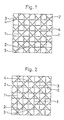
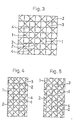
- Texeture of tetraaxial woven fabrics according to the present invention are as shown in plan views in Figs. 1 through 5.
- the upper yarns are upper bias yarns (3) running from the left top to the right bottom in the drawing.
- the lower bias yarns (4) run and warp ends (1) run further below.
- the lower bias yarns (4) and warp ends (1) are intermediate yarns running on respective two levels in mere flat stack relation without interlaced with any other yarns.
- the lower yarns are weft ends (2), and the upper bias yarns (3) pass through under the weft ends (2), return to the upper level, press down the warp ends (1) and the lower bias yarns (4), and then again pass through under the next weft ends (2).
- the intermediate yarns on the respective two levels are positionally fixed at intersections of the upper bias yarns (3) and weft ends (2) and cause no slippage of stitches.
- This texture is woven by depressing the upper bias yarns (3) for providing a shed and inseting weft ends (2) through the shed thus formed. Shedding at the upper bias yarns (3) depends on the bias yarn depressing heddles as shown in Figs. 9 and 10.
- the texture in Fig. 2 corresponds to the so-called plain weave and is composed of warp ends (1) as upper yarns and weft ends (2) as lower yarns, in which the warp ends (1) only alternately form a shed and the intermediate yarns, that is, the upper and lower bias yarns (3) and (4), respectively, are interposed between the warp and weft ends while kept in a mere flat stack relation.
- a weaving machine to be used is of the structure in which only the warp ends (1) alternately form a shed by means of eyelet heddles as shown in Figs. 11 and 12.
- the upper yarns are warp ends (1) which are all depressed to form a shed repeatedly and intersect the weft ends (2) for interposing the bias yarns running on the respective two levels, the weaving process being shown in Figs 13 and 14.
- the textures shown in Fig. 4 and Fig. 5 are examples of weave, in which the pitch between bias yarns is reduced to a half of that shown in Figs. 1 through 3 and, doubled in density;
- Fig. 4 shows that the warp ends (1) are all depressed for shedding and intersect the weft ends (2); and, in Fig. 5, the warp ends (1) form a shed at every other line of weft end (3) and intersect the weft ends.
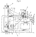
- the tetraaxial weaving machine of the present invention is characterized by comprising: a bias yarn creel (A) carrying a large number of bobbins or a plurality of a separate warp beams rotatably mounted on the surface thereof substantially perpendicular to the forward movement of the fabric; a bias yarn traversing device (B) for crosswise feeding of the upper bias yarns (3) and the lowr bias yarn (4) into the weaving area approximately throughout the width thereof; a warp feeding device (C) composed of a warp beam (15) and a warp guide roll (16) for feeding the warp ends (1) into the weaving area; a heddle device (D) for the upper yarns; a weft inserting device (E), a beating-up reed device (F), and a product taking-up device (G); the details thereof being described by way of an example shown in Figs. 6 and 7.
- bias yarn bobbin (5) are arranged on the outer periphery of an annular bias yarn creel (A) supported by a plurality of supporting rollers (8) and rotated by the internal transmission gear (9) connected to a driving device.
- These bias yarn bobbins (5) may be replaced by a plurality of separate warp beams.
- the bias yarn traversing device (B) is of the following structure.
- an upper bias yarn shifting roll (11) and lowe bias yarn shifting roll (10), both being provided with screw-like grooves (23) engraved at the same pitches in the same direction and having the number of pitches equal to at least a half of the number of bias yarns to be fed within the weaving width, are rotated in the directions reverse to each other by the driving power transmitted through the shifting roll driving gear (12) lying thereabove.
- a guide bar (13) is disposed near the sides of the upper and lower bias yarn shifting rolls facing the creel, and supported by guide bar supporting arms (14) so as to be shifted intermittently (or continuously when required) at a picking pitch.
- Rotations of the bias yarn shifting rolls (11), (10) are synchronous with those of the creel.
- An upper and lower bias yarn turning-over arm (26) to rotate radially with respect to the guide bar is provided on the end of the guide bar and the action thereof will be described later.
- the warp ends (1) are guided from the warp beam (15) to run below the upper and lower bias yarns (3), (4) by the warp feeding device (C) comprising the warp guide roll (16) and others, and, into a shed formed by the shedding heddles, a weft end (2) is inserted with the shuttle or rapier, when the reed device (F) for beating-up operate as follows: Any of the upper and lower reed (21) and (22), respectively, is always positioned at the fell of cloth for providing a shed between warp ends (1), for example, when the lower reed (22) lies at the fell of cloth, the upper reed (21) operates for inserting a weft end (2) and, on the way of weft insertion, the lower reed downwardly leaves from warp ends at the fell of cloth and approaches the heddles in preparation for weft insertion into the next shed.
- the upper and lowr reeds (21), (22) alternately enter into the warp sheet near the heddles for weft insertion while maintaining parallelism between warp ends as well as bias yarns at every rotation of the weaving machine, that is every weft insertion operation and operate to support bias yarns and warp ends at the fell of cloth. All yarns are woven into a fabric through the upper and lower reeds (21), (22) and the fabric thus woven up is wound as a final product (24) on the takingup roll (25) which is a principal member of the product taking-up device (G).
- the shifting rolls provided with screw-like grooves running in the same direction (for example, right hand screw) and at the same pitches are rotated in the opposite directions, and, therefore, the upper bias yarns (3) are shifted to the right side in Fig. 7 in succession whereas the lower bias yarns (4) to the left side at weaving pitches, whereby the bias yarn creel A rotates clockwise synchronously with the shifting rolls at the same pitches as above.
- the upper bias yarn (3) upon arrival at the right end in Fig. 7 slips off the end of the guide bar (13); positioned as shown by an alternate long and short dash line in Fig.
- bias yarn traversing device (B) can be modified into another structure.
- An example is as shown in Fig. 15 and comprises bias yarn guide pins (30) in number equal to at least the number of bias yarns to be fed into the weaving area, and endless chain (31) in the form of an ellipse running on a plane perpendicular to the weaving width, and chain sprockets (32), (33) disposed on both ends of the ellipse of chain, in which bias yarns fed from above and those from below into the weaving area serve as upper bias yarns (3) and lower bias yarns (4), respectively.
- This transversing device is characterized by comprising: two sheets of upper grooved shifting plates (42a), (42b) disposed front and back in the space above the weaving level and provided with yarn guide grooves (41) in number equal to at least a half of total number of upper and lowr bias yarns (3) to be fed into the weaving width which are engraved at lower edge for shifting the upper bias yarns right and left at one-groove pitch or longer; two sheets of lower grooved shifting plates (43a), (43b) disposed front and back in the space below the weaving level and provided with similar yarn guide grooves engraved at upper edge for shifting the lower bias yarns (4) right and left in the direction reverse to that of the upper grooved shifting plates (42a), (42b) at one-groove pitch or longer; and a dividing guide (44) slightly shorter than the length of the yarn guide groove part (41) of the upper and lower grooved shifting plates (42a), (43a) which is disposed fully close to the upper and lower shifting plates (42a), (43a) at the side
- the upper and lower bias yarns (3) and (4) fed from the bias yarn creel (A) are respectively divided to run above and below by the dividing roller (44) disposed horizontally ahead of the center of the creel (A) and having a length approximate to the weaving length.
- the upper and lower bias yarns (3), (4) are extended to the fell of cloth (48) while constantly pressed from above and below by the upper and lower grooved shifting plates (42b), (43b) provided with yarn guide grooves (41), (41) each in number equal to at least a half of the number of the upper and lower bias yarns (3) or (4) to be fed throughout the weaving width, and fixed ny the metallic fixtures (45) with the yarn guide grooves (41), (41) opposed to each other.
- the upper and lower grooved plates (42a), (43a) are supported by a guide pole (49) to be shiftable vertically and horizontally through a guide hole (49a) of the post (49), and, as shown in Fig. 17, are adapted to perform a square-path movement as travelling upward, righward (leftward), downward, and leftward (rightward) by a driving mechanism (W) as shown in Fig. 16 every time when the warp ends (1) fed from the warp feeding device (C) consisting of the warp beam (15) and the warp guide roll (16) are downwardly drawn by the needle-heddles (27) and a weft end (2) is inserted by the weft insertion device (E) through the upper and lower bias yarns (3), (4). Though only one driving mechanism (W) for the lower shifting plate (43a) is shown in Fig. 16, the similar mechanism for the upper grooved shifting plate (42a) is provided in a higher position.
- the upper grooved shifting plates (42a) descends and retains, at yarn guide grooves thereof, each and every upper bias yarns (3) having been retained by the upper grooved shifting plate (42b) on the rear side, furrher descends to release the yarns from the upper plate (42b), moves rightward at a distance longer than one groove pitch and ascends, and adapts the upper yarns (3) to be retained by the guide grooves (41) of the upper shifting plate (42b) lying in a position moved at a distance longer than one groove pitch.
- the upper grooved shifting plate (42a) further ascends, leaves from the upper bias yarns (3), as shown in Fig. 17 and, after moving leftward at a distance longer than one groove pitch, returns to the initial position.
- the lower grooved shifting plate (43a) operates in a mode contrary to that of the abovesaid upper shifting plate (42a) in order to shift leftward the lower bias yarns in succession.
- the upper and lower yarns (3), (4) are respectively shifted in the opposite directions and, every time of completion of weft insertion into a shet formed by the warp ends (1) and the upper and lower bias yarns (3), (4), the warp ends (1) rise above the upper and lower bias yarns (3), (4) (as shown in Fig. 18).
- the upper grooved shifting plate (42a) descends and shift, while depressing, the upper bias yarns (3) rightward in succession and, on the contrary, the lower shifting plate (43a) ascends and shifts the lower bias yarns (4) leftward in succession, whereby the upper and lower bias yarns (3), (4) intersect each other in bias relation with respect to the warp and weft ends (1) and (2), respectively, at the fell of cloth to weave up a tetraaxial fabric.
- the driving mechanism (W) for driving the lower grooved shifting plate (43a) as shown in Fig. 16 will be described.
- a cam driving shaft (53) is rotated by the rotation of the main shaft (50) of the weaving machine through gears I (51) and II (52).
- the cam driving shaft (53) is fitted with a cam (60) for horizontally shifting the lower grooved shifting plate (43a) and another cam (61) for vertical shift thereof.
- the horizontal shifting cam (60) causes a cam lever (62a), which is formed into a torsion spring (68) at the middle portion and provided with a cam roller (64a) at the lower part, to reciprocate in the horizontal direction. Since the tip of the cam lever (62a) is connected to the lower grooved shifting plate (43a) at an acting point (65), the lower shifting plate (43a) horizontally reciprocates in association with the movement of the cam lever (62a).
- the torsion spring (68) functions to constantly press the cam roller (64a) to the horizontal shifting cam (60).
- the vertical shifting cam (61) causes a cam roller (64b) positioned at the end of a cam lever (62b) having a fulcrum (67) at the middle part thereof to swing vertically, whereby a cam rod (63) bearingly supported at the other end of the cam lever (62b) vertically reciprocates. Since the cam rod (63) is connected to the lower grooved shifting plate (43a) at the acting point (65) on the tip thereof, the lower plate (43a) vertically reciprocates in association with the movement of the cam rod (63).
- the cam roller (64b) is constantly pressed to the vertical shifting cam (61) by a coiled spring (69) on the other end of the cam lever (62b) to which the cam roller (64) is fixed.
- the driving mechanism (W) of such structure as above provides a fabric having texture composed of upper and lower bias yarns (3), (4) running crosswise with respect to warp and weft ends (1), (2).
- the balancing spring 57 constantly exerts tension on the upper and lower bias yarns running between the bias yarn bobbins (5) and the yarn guide grooves (41), (41) of the upper and lower grooved shifting plates (42a), (43a).
- the upper and lower bias yarns (3), (4) are successively turned over and obliquely run from right to left or vice versa, thereby composing a fabric.
- the upper and lower grooved shifting plates (42b), (43b) are set unmovably and the other ones (42a), (43a) are adapted to move along a triangular path running in the directions reverse to each other in the space in front of the former shifting plates (42b), (43b).
- the upper grooved shifting plate (42a) it descends, stops after releasing the upper bias yarn from the guide groove of the upper shifting plate (42b), ascends obliquely and upwardly, and, on the way of ascending, places the released upper bias yarn (3) on a guide groove on the left side one or more grooves distant from the first groove, further ascends leftwardly and upwardly to the initial position, thereby performing a right-angled triangular-path circulatory movement.
- the upper shifting plate (42a) is obliquely lowered from the upper right-hand position to the lower left-hand position toward the upper bias yarn (3) retained in the guide groove of the stationary upper shifting plate (42b), receives the yarn (3) on the way of lowering and releases the yarn from the groove of the upper plate (42b), stops after continuous oblique ascending to the lower left-hand position while retaining the yarn (3), obliquely ascends to the upper left-hand position and shifts, on the way of ascending, the yarn from the groove of the upper plate (42b) to the other groove on the left side one or more grooves distant from the upper shifting plate (42b), further continues oblique ascending to the upper left-hand position, and, after reaching the initial level, moves rightward to return to the initial position, thereby performing an equilateral triangular-path movement.
- the upper grooved shifting plates (42a), (42b) and the lower plates (43a), (43b) are all movable.
- the upper and lower plates (42a), (43a) in the forward position move up and down in the opposite directions whereas the other plates (42b), (43b) in the rear position move right and left in the opposite directions for shifting the upper and lower bias yarns right and left in the opposite directions in a distance of one or more groove pitches.
- the movement in this case will be described referring to the upper grooved shifting plates (42a), (42b) as follows:
- the upper bias yarn (3) retained in the guide groove of the upper plate (42b) movable only right and left is released therefrom by lowering of the upper plate (42a) movable only up and down. While the upper yarn (3) is kept released, the upper plate (42b) moves rightward and, at a position reached thereby, catches, with the guide groove thereof, the upper yarn having been raised with the rise of the upper plate (42a) which has been lowered before. Even after placing the upper yarn (3) in the groove of the upper plate (42b), another upper plate (42a) rises to the upper limit so as not to interfere with the right and left movement of the upper bias yarn (3).
- the upper plate (42b) having caught the upper bias yarn (3) moves leftward at a distance of one or more groove pitches, when the upper plate (42a) having reached the upper limit lowers and, while retaining the yarn with a groove one or grooves distant from the first groove, descends to the lower limit. Afterward, the similar operation is repeated to shift the upper yarns (3) at a distance of one or more groove pitches in turn.
- the pitch of shift is determined by the number of bias yarns per unit length of the fabric.
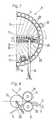
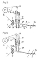
- Figs. 9 and 10 illustrate the state of weaving by means of bias yarn pushing heddles to form a shed while moving the upper bias yarns (3) only, in which the upper bias yarns (3) are on the highest of weaving levels with the lower bias yarns (4) and warp ends (1) positioned lower in sequence, and the upper bias yarns (3) on the highest level are pressed downward lower than the other three kinds of yarns for shedding (as shown by the alternate long and short dash line in Fig. 10) and to insert the weft end (2) therethrough by the rapier or shuttle (not shown). Depression of the upper bias yarns (3) for shedding depends on the heddle device (D) exclusive for the upper yarns.
- D heddle device
- the state of operation is shown in Fig. 9.
- a textraaxial fabric woven by this method therefore, is in such structure that all upper bias yarns (3) run in the same direction, always press the lower bias yarns (4) (bias yarns crossing perpendicularly to upper ones) and warp ends (1), and then sink to the lower position, the level of the weft ends (2) being below that of the warp ends (1) as illustrated in Fig. 1.
- Weaving may depend on shedding of the upper bias yarns at every other end and alternately, and, for this purpose, the pushing heddles (18) as shown in Figs. 9 and 10 are disposed for every other end and the heddle frames (19) are alternately shifted right and left at a distance of one pitch.
- Figs. 11 through 14 are views showing a method of weaving using the warp heddles, among which Figs. 11 and 12 show alternate shedding with warp ends interlaced with weft ends in one-up-one-down pattern to provide the so-called plain weave having the upper and lower bias yarns woven thereinto while merely laid flat between the warp and weft ends.
- alternately performed are shedding by means of front needle heddles (27) of the heddle frame (19) two rows (one row allowable) ahead of the warp heddle frame (19) shown in Fig. 11, shed closing as shown in Fig. 12, and shedding by the rear needle heddles (28) as shown in Fig. 11, the process being usual shedding and readily understood.
- a fabric texture thus produced is as shown in Fig. 2.
- Figs. 13 and 14 show a state in which all warp ends are shedded simultaneously, however, the state is not so different from that of plain weave as described above except a difference in the movement of heddle frames (19).
- a fabric texture obtained is as shown in Fig. 3, which is composed of warp ends (1), upper bias yarns (3), lower bias yarns (4), and weft ends (2) layered in the order from top to bottom.
- the reference character 20 in Figs. 11 and 13 indicates a picking rapier.
- a textraaxial woven fabric of the present invention as has detailedly been described as above possesses isotropy in strength and elongation characteristics and, even thinner than the conventional type fabrics, exhibits isotropic nature of higher level.
- a tetraaxial weaving machine of the present invention equipped with a novel device of bias yarn feeding and traversing device enables high speed weaving advantageous for mass production and consequent cost reduction.
Landscapes
- Engineering & Computer Science (AREA)
- Textile Engineering (AREA)
- Woven Fabrics (AREA)
- Looms (AREA)
- Treatments For Attaching Organic Compounds To Fibrous Goods (AREA)
- Organic Low-Molecular-Weight Compounds And Preparation Thereof (AREA)
Priority Applications (1)
| Application Number | Priority Date | Filing Date | Title |
|---|---|---|---|
| AT87114141T ATE99744T1 (de) | 1986-10-01 | 1987-09-28 | Tetraaxialgewebe und webstuhl zum herstellen von tetraaxialgewebe. |
Applications Claiming Priority (2)
| Application Number | Priority Date | Filing Date | Title |
|---|---|---|---|
| JP61235168A JPS6392751A (ja) | 1986-10-01 | 1986-10-01 | 四軸織物及び四軸織機 |
| JP235168/86 | 1986-10-01 |
Publications (3)
| Publication Number | Publication Date |
|---|---|
| EP0263392A2 true EP0263392A2 (fr) | 1988-04-13 |
| EP0263392A3 EP0263392A3 (fr) | 1991-03-06 |
| EP0263392B1 EP0263392B1 (fr) | 1994-01-05 |
Family
ID=16982066
Family Applications (1)
| Application Number | Title | Priority Date | Filing Date |
|---|---|---|---|
| EP87114141A Expired - Lifetime EP0263392B1 (fr) | 1986-10-01 | 1987-09-28 | Tissu tétra-axial et métier à tisser des tissus triaxiaux |
Country Status (4)
| Country | Link |
|---|---|
| EP (1) | EP0263392B1 (fr) |
| JP (1) | JPS6392751A (fr) |
| AT (1) | ATE99744T1 (fr) |
| DE (2) | DE3788697T2 (fr) |
Cited By (24)
| Publication number | Priority date | Publication date | Assignee | Title |
|---|---|---|---|---|
| EP0536735A1 (fr) * | 1991-10-11 | 1993-04-14 | D.I.M.A. RICERCHE TECNOLOGICHE S.r.l. | Tissu tétra-axial et métier à tisser pour sa fabrication |
| WO1994016131A1 (fr) * | 1993-01-08 | 1994-07-21 | Short Brothers Plc | Structure multiaxiale de fils |
| FR2702222A1 (fr) * | 1993-03-03 | 1994-09-09 | Cotton Freres Cie | Tissu tridimensionnel multiaxial et son procédé de fabrication. |
| EP0643161A1 (fr) * | 1993-09-08 | 1995-03-15 | Howa Machinery Limited | Tissu multi-axial et métier à tisser pour sa fabrication |
| US5472020A (en) * | 1993-09-08 | 1995-12-05 | Howa Machinery, Ltd. | Multi-axial fabric with triaxial and quartaxial portions |
| WO1996006213A1 (fr) * | 1994-08-18 | 1996-02-29 | Short Brothers Plc | Dispositif permettant de constituer un assemblage de fils biais |
| US5947160A (en) * | 1995-02-06 | 1999-09-07 | Short Brothers Plc | Loop holding mechanism for use in a multi-axial yarn structure forming machine |
| EP0957191A3 (fr) * | 1998-04-07 | 1999-12-15 | Leonardo Lenzi | Procédé et dispositif pour la fabrication d'articles textiles |
| WO2000009059A3 (fr) * | 1998-08-14 | 2000-06-29 | Prodesco | Structure tissee extenseur/greffon |
| WO2003085182A1 (fr) * | 2002-04-10 | 2003-10-16 | Rongde Ge | Procede de tissage de fils de chaine ondules et tissu |
| WO2003012184A3 (fr) * | 2001-07-31 | 2003-12-24 | Mamiliano Dini | Tissu tetraxial et machine permettant de fabriquer ledit tissu |
| WO2004059054A1 (fr) * | 2002-12-27 | 2004-07-15 | Tecminho | Tissu multiaxial et machine a tisser pour sa fabrication |
| WO2009001282A1 (fr) * | 2007-06-25 | 2008-12-31 | Universidade Do Minho | Métier à tisser multi-axial |
| WO2010004284A1 (fr) * | 2008-07-11 | 2010-01-14 | Griffith Textile Machines Limited | Tissu multiaxial |
| DE102010007048A1 (de) | 2010-02-06 | 2011-08-11 | Lindauer DORNIER Gesellschaft mit beschränkter Haftung, 88131 | Verfahren und Webmaschine zur Herstellung von Geweben mit Zusatzschusseffekten |
| CN103109007A (zh) * | 2010-08-20 | 2013-05-15 | 林道尔·多尼尔有限责任公司 | 用于在带有附加花纹效果的织物中形成织造花纹的织筘和织机 |
| WO2014112931A1 (fr) * | 2013-01-21 | 2014-07-24 | Autoliv Development Ab | Améliorations à ou associés à des coussins de sécurité gonflable |
| CN104040055A (zh) * | 2012-01-20 | 2014-09-10 | 林道尔·多尼尔有限责任公司 | 带有用于形成附加纬面花纹的装置的织机 |
| WO2016020316A1 (fr) * | 2014-08-07 | 2016-02-11 | Rheinisch-Westfälische Technische Hochschule (Rwth) Aachen | Fabrication d'une matière textile de renforcement pour un matériau composite à base de fibres |
| EP3141642A1 (fr) * | 2015-09-10 | 2017-03-15 | Textilma Ag | Métier à tisser destiné à la fabrication de produits tissés dotés d'un fil à poser ou à tricoter incorporé |
| US9763012B2 (en) | 2011-03-30 | 2017-09-12 | Bose Corporation | Monofilament fabric acoustic suspension elements |
| DE102018201254A1 (de) * | 2018-01-29 | 2019-08-01 | Audi Ag | Gasdruckspeicher, Verfahren zur Herstellung eines Gasdruckspeichers und Vorrichtung zur Durchführung des Verfahrens |
| CN113584682A (zh) * | 2021-07-21 | 2021-11-02 | 航宸石家庄新材料科技有限公司 | 一种生产平面三向织物的圆织机 |
| CN116145303A (zh) * | 2021-11-19 | 2023-05-23 | 北京方硕复合材料技术有限公司 | 一种织物的编织方法及织物 |
Families Citing this family (6)
| Publication number | Priority date | Publication date | Assignee | Title |
|---|---|---|---|---|
| JP2672832B2 (ja) * | 1988-05-14 | 1997-11-05 | 通弘 小河原 | 四軸織機 |
| JPH068971Y2 (ja) * | 1988-08-29 | 1994-03-09 | 東レ株式会社 | ヘルメット |
| JPH0258928U (fr) * | 1988-10-20 | 1990-04-27 | ||
| JP3228974B2 (ja) * | 1990-12-19 | 2001-11-12 | ローム株式会社 | ライン型サーマルプリントヘッド |
| JP4841887B2 (ja) * | 2005-07-27 | 2011-12-21 | 明大株式会社 | 四軸織機における斜糸移送装置 |
| DE102017216026B4 (de) * | 2017-09-12 | 2022-01-27 | Adidas Ag | Gewebtes Schuhoberteil |
Family Cites Families (7)
| Publication number | Priority date | Publication date | Assignee | Title |
|---|---|---|---|---|
| GB1157526A (en) * | 1965-12-20 | 1969-07-09 | Gen Electric | Improvements in Three Yarn Set Fabrics. |
| US4015637A (en) * | 1974-11-11 | 1977-04-05 | N.F. Doweave, Inc. | Triaxial fabric forming machine and components thereof |
| US3999578A (en) * | 1975-08-11 | 1976-12-28 | Barber-Colman Company | Triaxial weaving machine with heddle shifting means and method |
| US4031922A (en) * | 1976-03-25 | 1977-06-28 | Barber-Colman Company | Vertically arranged triaxial weaving machine |
| JPS5642380A (en) * | 1979-09-14 | 1981-04-20 | Toshiba Corp | Manufacture of schottky barrier type semiconductor device |
| GB2117418A (en) * | 1982-03-19 | 1983-10-12 | Hinaya Kk | Fabric and tubular article using said fabric |
| JPS58163750A (ja) * | 1982-03-19 | 1983-09-28 | 伊豆蔵 明彦 | 織物 |
-
1986
- 1986-10-01 JP JP61235168A patent/JPS6392751A/ja active Pending
-
1987
- 1987-09-28 DE DE87114141T patent/DE3788697T2/de not_active Expired - Lifetime
- 1987-09-28 AT AT87114141T patent/ATE99744T1/de not_active IP Right Cessation
- 1987-09-28 DE DE198787114141T patent/DE263392T1/de active Pending
- 1987-09-28 EP EP87114141A patent/EP0263392B1/fr not_active Expired - Lifetime
Cited By (46)
| Publication number | Priority date | Publication date | Assignee | Title |
|---|---|---|---|---|
| US5351722A (en) * | 1991-10-11 | 1994-10-04 | D.I.M.A. Ricerche Technologiche S.R.L. | Tetraxial fabric and weaving machine for its manufacture |
| EP0536735A1 (fr) * | 1991-10-11 | 1993-04-14 | D.I.M.A. RICERCHE TECNOLOGICHE S.r.l. | Tissu tétra-axial et métier à tisser pour sa fabrication |
| GB2278854B (en) * | 1993-01-08 | 1996-12-04 | Short Brothers Plc | A multi-axial yarn structure |
| WO1994016131A1 (fr) * | 1993-01-08 | 1994-07-21 | Short Brothers Plc | Structure multiaxiale de fils |
| GB2278854A (en) * | 1993-01-08 | 1994-12-14 | Short Brothers Plc | A multi-axial yarn structure |
| US5540260A (en) * | 1993-01-08 | 1996-07-30 | Short Brothers Plc | Multi-axial yarn structure and weaving method |
| FR2702222A1 (fr) * | 1993-03-03 | 1994-09-09 | Cotton Freres Cie | Tissu tridimensionnel multiaxial et son procédé de fabrication. |
| WO1994020658A1 (fr) * | 1993-03-03 | 1994-09-15 | C.T.M.I. Cotton Textiles Pour Materiaux Innovants | Tissu tridimensionnel multiaxial et son procede de fabrication |
| EP0643161A1 (fr) * | 1993-09-08 | 1995-03-15 | Howa Machinery Limited | Tissu multi-axial et métier à tisser pour sa fabrication |
| US5472020A (en) * | 1993-09-08 | 1995-12-05 | Howa Machinery, Ltd. | Multi-axial fabric with triaxial and quartaxial portions |
| WO1996006213A1 (fr) * | 1994-08-18 | 1996-02-29 | Short Brothers Plc | Dispositif permettant de constituer un assemblage de fils biais |
| US5775381A (en) * | 1994-08-18 | 1998-07-07 | Short Brothers Plc | Bias yarn assembly forming device |
| US5947160A (en) * | 1995-02-06 | 1999-09-07 | Short Brothers Plc | Loop holding mechanism for use in a multi-axial yarn structure forming machine |
| EP0957191A3 (fr) * | 1998-04-07 | 1999-12-15 | Leonardo Lenzi | Procédé et dispositif pour la fabrication d'articles textiles |
| WO2000009059A3 (fr) * | 1998-08-14 | 2000-06-29 | Prodesco | Structure tissee extenseur/greffon |
| US6123115A (en) * | 1998-08-14 | 2000-09-26 | Prodesco, Inc. | Weaving shuttle |
| US6159239A (en) * | 1998-08-14 | 2000-12-12 | Prodesco, Inc. | Woven stent/graft structure |
| US6164339A (en) * | 1998-08-14 | 2000-12-26 | Prodesco, Inc. | Method of forming a woven textile |
| US6192944B1 (en) | 1998-08-14 | 2001-02-27 | Prodesco, Inc. | Method of forming a textile member with undulating wire |
| US7237575B2 (en) | 2001-07-31 | 2007-07-03 | Tetraxial S.R.L. | Tetraxial fabric and machine for its manufacture |
| WO2003012184A3 (fr) * | 2001-07-31 | 2003-12-24 | Mamiliano Dini | Tissu tetraxial et machine permettant de fabriquer ledit tissu |
| WO2003085182A1 (fr) * | 2002-04-10 | 2003-10-16 | Rongde Ge | Procede de tissage de fils de chaine ondules et tissu |
| WO2004059054A1 (fr) * | 2002-12-27 | 2004-07-15 | Tecminho | Tissu multiaxial et machine a tisser pour sa fabrication |
| WO2009001282A1 (fr) * | 2007-06-25 | 2008-12-31 | Universidade Do Minho | Métier à tisser multi-axial |
| WO2010004284A1 (fr) * | 2008-07-11 | 2010-01-14 | Griffith Textile Machines Limited | Tissu multiaxial |
| DE102010007048A1 (de) | 2010-02-06 | 2011-08-11 | Lindauer DORNIER Gesellschaft mit beschränkter Haftung, 88131 | Verfahren und Webmaschine zur Herstellung von Geweben mit Zusatzschusseffekten |
| WO2011095262A1 (fr) | 2010-02-06 | 2011-08-11 | Lindauer Dornier Gesellschaft Mit Beschränkter Haftung | Procédé et métier à tisser pour la production de tissus à effets trame supplémentaires |
| CN103109007A (zh) * | 2010-08-20 | 2013-05-15 | 林道尔·多尼尔有限责任公司 | 用于在带有附加花纹效果的织物中形成织造花纹的织筘和织机 |
| US8770235B2 (en) | 2010-08-20 | 2014-07-08 | Lindauer Dornier Gesellschaft Mbh | Reed and weaving machine for weaving pattern formation in woven fabrics with additional pattern effects |
| CN103109007B (zh) * | 2010-08-20 | 2014-12-17 | 林道尔·多尼尔有限责任公司 | 用于在带有附加花纹效果的织物中形成织造花纹的织筘和织机 |
| US9763012B2 (en) | 2011-03-30 | 2017-09-12 | Bose Corporation | Monofilament fabric acoustic suspension elements |
| CN104040055A (zh) * | 2012-01-20 | 2014-09-10 | 林道尔·多尼尔有限责任公司 | 带有用于形成附加纬面花纹的装置的织机 |
| CN104919100A (zh) * | 2013-01-21 | 2015-09-16 | 奥托立夫开发公司 | 安全气囊或有关安全气囊的改进 |
| WO2014112931A1 (fr) * | 2013-01-21 | 2014-07-24 | Autoliv Development Ab | Améliorations à ou associés à des coussins de sécurité gonflable |
| US10583802B2 (en) | 2013-01-21 | 2020-03-10 | Autoliv Development Ab | In or relating to air-bags |
| CN104919100B (zh) * | 2013-01-21 | 2017-07-25 | 奥托立夫开发公司 | 安全气囊或有关安全气囊的改进 |
| WO2016020316A1 (fr) * | 2014-08-07 | 2016-02-11 | Rheinisch-Westfälische Technische Hochschule (Rwth) Aachen | Fabrication d'une matière textile de renforcement pour un matériau composite à base de fibres |
| CN108699736B (zh) * | 2015-09-10 | 2020-06-12 | 泰克斯蒂尔玛股份公司 | 用于制造具有编入针织线或包覆线的机织织物的织机 |
| CN108699736A (zh) * | 2015-09-10 | 2018-10-23 | 泰克斯蒂尔玛股份公司 | 用于制造具有编入针织线或包覆线的机织织物的织机 |
| WO2017042015A1 (fr) * | 2015-09-10 | 2017-03-16 | Textilma Ag | Métier à tisser conçu pour produire des articles tissés dans lesquels sont incorporés des fils de tricotage ou des fils de jetage |
| US10597802B2 (en) | 2015-09-10 | 2020-03-24 | Textilma Ag | Loom for producing woven material, having incorporated knitting threads or cover threads |
| EP3141642A1 (fr) * | 2015-09-10 | 2017-03-15 | Textilma Ag | Métier à tisser destiné à la fabrication de produits tissés dotés d'un fil à poser ou à tricoter incorporé |
| DE102018201254A1 (de) * | 2018-01-29 | 2019-08-01 | Audi Ag | Gasdruckspeicher, Verfahren zur Herstellung eines Gasdruckspeichers und Vorrichtung zur Durchführung des Verfahrens |
| US11885463B2 (en) | 2018-01-29 | 2024-01-30 | Audi Ag | Pressurized gas accumulator, method for producing a pressurized gas accumulator, and device for carrying out the method |
| CN113584682A (zh) * | 2021-07-21 | 2021-11-02 | 航宸石家庄新材料科技有限公司 | 一种生产平面三向织物的圆织机 |
| CN116145303A (zh) * | 2021-11-19 | 2023-05-23 | 北京方硕复合材料技术有限公司 | 一种织物的编织方法及织物 |
Also Published As
| Publication number | Publication date |
|---|---|
| ATE99744T1 (de) | 1994-01-15 |
| DE3788697D1 (de) | 1994-02-17 |
| DE263392T1 (de) | 1988-09-01 |
| EP0263392A3 (fr) | 1991-03-06 |
| DE3788697T2 (de) | 1994-04-28 |
| JPS6392751A (ja) | 1988-04-23 |
| EP0263392B1 (fr) | 1994-01-05 |
Similar Documents
| Publication | Publication Date | Title |
|---|---|---|
| EP0263392B1 (fr) | Tissu tétra-axial et métier à tisser des tissus triaxiaux | |
| US6539983B2 (en) | Woven material comprising tape-like warp and weft | |
| CA2263202A1 (fr) | Dispositif de commande de fils de trame destines a la production de tissus pour gaze sur une machine textile | |
| CA2455835C (fr) | Tissu tetraxial et machine permettant de fabriquer ledit tissu | |
| JP2005522589A (ja) | シャットル織機織物曲線製織方法及び製品 | |
| EP0632152A1 (fr) | Courroie epaisse et appareil pour sa fabrication | |
| US3746051A (en) | Machine for making a partly woven and partly knitted fabric | |
| US5375627A (en) | Method and weaving machine for producing multi-axial fabric | |
| CN1751146A (zh) | 用于制造平纹和纱罗组织织物的方法以及用于实施该方法的织机 | |
| GB2113725A (en) | Circular looms | |
| US4846229A (en) | Circular loom | |
| RU2301853C2 (ru) | Ткацкий станок для изготовления ткани в полотняном и перевивочном переплетении (варианты) | |
| JPS6320933B2 (fr) | ||
| US3309901A (en) | Apparatus for reinforcing a fibrous material | |
| US5472020A (en) | Multi-axial fabric with triaxial and quartaxial portions | |
| KR100925014B1 (ko) | 자카드가 표현된 벨벳 및 이를 제조하는 장치와 그제조방법 | |
| US3735606A (en) | Method and apparatus for the production of textile fabrics and the fabric produced thereby | |
| JPH03185148A (ja) | 織布側縁部のからみ織り装置 | |
| JP2672832B2 (ja) | 四軸織機 | |
| CN87103174A (zh) | 双梭口双投梭织机和双幅织造 | |
| US4579151A (en) | Machine for making a partly woven partly knitted fabric | |
| US4628711A (en) | Process for manufacturing a patterned warp-knitted material and a warp knitting machine for its use | |
| US626149A (en) | L desmarais | |
| JPH049218B2 (fr) | ||
| CN223738254U (zh) | 一种织布机的经线调节限位机构 |
Legal Events
| Date | Code | Title | Description |
|---|---|---|---|
| PUAI | Public reference made under article 153(3) epc to a published international application that has entered the european phase |
Free format text: ORIGINAL CODE: 0009012 |
|
| AK | Designated contracting states |
Kind code of ref document: A2 Designated state(s): AT BE CH DE ES FR GB GR IT LI LU NL SE |
|
| EL | Fr: translation of claims filed | ||
| TCAT | At: translation of patent claims filed | ||
| DET | De: translation of patent claims | ||
| PUAL | Search report despatched |
Free format text: ORIGINAL CODE: 0009013 |
|
| AK | Designated contracting states |
Kind code of ref document: A3 Designated state(s): AT BE CH DE ES FR GB GR IT LI LU NL SE |
|
| 17P | Request for examination filed |
Effective date: 19910827 |
|
| 17Q | First examination report despatched |
Effective date: 19920807 |
|
| GRAA | (expected) grant |
Free format text: ORIGINAL CODE: 0009210 |
|
| AK | Designated contracting states |
Kind code of ref document: B1 Designated state(s): AT BE CH DE ES FR GB GR IT LI LU NL SE |
|
| PG25 | Lapsed in a contracting state [announced via postgrant information from national office to epo] |
Ref country code: NL Effective date: 19940105 Ref country code: GR Free format text: LAPSE BECAUSE OF FAILURE TO SUBMIT A TRANSLATION OF THE DESCRIPTION OR TO PAY THE FEE WITHIN THE PRESCRIBED TIME-LIMIT Effective date: 19940105 Ref country code: SE Effective date: 19940105 Ref country code: AT Effective date: 19940105 Ref country code: BE Effective date: 19940105 |
|
| REF | Corresponds to: |
Ref document number: 99744 Country of ref document: AT Date of ref document: 19940115 Kind code of ref document: T |
|
| ET | Fr: translation filed | ||
| REF | Corresponds to: |
Ref document number: 3788697 Country of ref document: DE Date of ref document: 19940217 |
|
| ITF | It: translation for a ep patent filed | ||
| PG25 | Lapsed in a contracting state [announced via postgrant information from national office to epo] |
Ref country code: ES Free format text: LAPSE BECAUSE OF FAILURE TO SUBMIT A TRANSLATION OF THE DESCRIPTION OR TO PAY THE FEE WITHIN THE PRESCRIBED TIME-LIMIT Effective date: 19940416 |
|
| NLV1 | Nl: lapsed or annulled due to failure to fulfill the requirements of art. 29p and 29m of the patents act | ||
| PLBE | No opposition filed within time limit |
Free format text: ORIGINAL CODE: 0009261 |
|
| STAA | Information on the status of an ep patent application or granted ep patent |
Free format text: STATUS: NO OPPOSITION FILED WITHIN TIME LIMIT |
|
| 26N | No opposition filed | ||
| PGFP | Annual fee paid to national office [announced via postgrant information from national office to epo] |
Ref country code: LU Payment date: 19960930 Year of fee payment: 10 |
|
| REG | Reference to a national code |
Ref country code: GB Ref legal event code: IF02 |
|
| PGFP | Annual fee paid to national office [announced via postgrant information from national office to epo] |
Ref country code: GB Payment date: 20060922 Year of fee payment: 20 Ref country code: FR Payment date: 20060922 Year of fee payment: 20 |
|
| PGFP | Annual fee paid to national office [announced via postgrant information from national office to epo] |
Ref country code: IT Payment date: 20060930 Year of fee payment: 20 |
|
| PGFP | Annual fee paid to national office [announced via postgrant information from national office to epo] |
Ref country code: CH Payment date: 20061006 Year of fee payment: 20 |
|
| PGFP | Annual fee paid to national office [announced via postgrant information from national office to epo] |
Ref country code: DE Payment date: 20061114 Year of fee payment: 20 |
|
| REG | Reference to a national code |
Ref country code: GB Ref legal event code: PE20 |
|
| REG | Reference to a national code |
Ref country code: CH Ref legal event code: PL |
|
| PG25 | Lapsed in a contracting state [announced via postgrant information from national office to epo] |
Ref country code: GB Free format text: LAPSE BECAUSE OF EXPIRATION OF PROTECTION Effective date: 20070927 |
|
| PG25 | Lapsed in a contracting state [announced via postgrant information from national office to epo] |
Ref country code: LU Free format text: LAPSE BECAUSE OF NON-PAYMENT OF DUE FEES Effective date: 19970930 |