EP0264111A1 - Automatische Blattzuführung für einen Drucker - Google Patents
Automatische Blattzuführung für einen Drucker Download PDFInfo
- Publication number
- EP0264111A1 EP0264111A1 EP87114964A EP87114964A EP0264111A1 EP 0264111 A1 EP0264111 A1 EP 0264111A1 EP 87114964 A EP87114964 A EP 87114964A EP 87114964 A EP87114964 A EP 87114964A EP 0264111 A1 EP0264111 A1 EP 0264111A1
- Authority
- EP
- European Patent Office
- Prior art keywords
- sheet feeder
- case
- continuous paper
- cut
- main body
- Prior art date
- Legal status (The legal status is an assumption and is not a legal conclusion. Google has not performed a legal analysis and makes no representation as to the accuracy of the status listed.)
- Granted
Links
- 230000007246 mechanism Effects 0.000 claims abstract description 41
- 238000007599 discharging Methods 0.000 claims abstract description 8
- 238000003780 insertion Methods 0.000 claims description 5
- 230000037431 insertion Effects 0.000 claims description 5
- 230000002452 interceptive effect Effects 0.000 description 2
- 230000005540 biological transmission Effects 0.000 description 1
- 238000012986 modification Methods 0.000 description 1
- 230000004048 modification Effects 0.000 description 1
- 230000001360 synchronised effect Effects 0.000 description 1
Images


Classifications
-
- B—PERFORMING OPERATIONS; TRANSPORTING
- B41—PRINTING; LINING MACHINES; TYPEWRITERS; STAMPS
- B41J—TYPEWRITERS; SELECTIVE PRINTING MECHANISMS, i.e. MECHANISMS PRINTING OTHERWISE THAN FROM A FORME; CORRECTION OF TYPOGRAPHICAL ERRORS
- B41J11/00—Devices or arrangements of selective printing mechanisms, e.g. ink-jet printers or thermal printers, for supporting or handling copy material in sheet or web form
-
- B—PERFORMING OPERATIONS; TRANSPORTING
- B41—PRINTING; LINING MACHINES; TYPEWRITERS; STAMPS
- B41J—TYPEWRITERS; SELECTIVE PRINTING MECHANISMS, i.e. MECHANISMS PRINTING OTHERWISE THAN FROM A FORME; CORRECTION OF TYPOGRAPHICAL ERRORS
- B41J29/00—Details of, or accessories for, typewriters or selective printing mechanisms not otherwise provided for
- B41J29/02—Framework
-
- B—PERFORMING OPERATIONS; TRANSPORTING
- B41—PRINTING; LINING MACHINES; TYPEWRITERS; STAMPS
- B41J—TYPEWRITERS; SELECTIVE PRINTING MECHANISMS, i.e. MECHANISMS PRINTING OTHERWISE THAN FROM A FORME; CORRECTION OF TYPOGRAPHICAL ERRORS
- B41J11/00—Devices or arrangements of selective printing mechanisms, e.g. ink-jet printers or thermal printers, for supporting or handling copy material in sheet or web form
- B41J11/48—Apparatus for condensed record, tally strip, or like work using two or more papers, or sets of papers, e.g. devices for switching over from handling of copy material in sheet form to handling of copy material in continuous form and vice versa or point-of-sale printers comprising means for printing on continuous copy material, e.g. journal for tills, and on single sheets, e.g. cheques or receipts
-
- B—PERFORMING OPERATIONS; TRANSPORTING
- B41—PRINTING; LINING MACHINES; TYPEWRITERS; STAMPS
- B41J—TYPEWRITERS; SELECTIVE PRINTING MECHANISMS, i.e. MECHANISMS PRINTING OTHERWISE THAN FROM A FORME; CORRECTION OF TYPOGRAPHICAL ERRORS
- B41J13/00—Devices or arrangements of selective printing mechanisms, e.g. ink-jet printers or thermal printers, specially adapted for supporting or handling copy material in short lengths, e.g. sheets
-
- B—PERFORMING OPERATIONS; TRANSPORTING
- B41—PRINTING; LINING MACHINES; TYPEWRITERS; STAMPS
- B41J—TYPEWRITERS; SELECTIVE PRINTING MECHANISMS, i.e. MECHANISMS PRINTING OTHERWISE THAN FROM A FORME; CORRECTION OF TYPOGRAPHICAL ERRORS
- B41J15/00—Devices or arrangements of selective printing mechanisms, e.g. ink-jet printers or thermal printers, specially adapted for supporting or handling copy material in continuous form, e.g. webs
Definitions
- the present invention relates to an automatic sheet feeder for a printer capable of selectively printing continuous paper and cut sheets.
- a printer of this type includes a printer body and an automatic sheet feeder, detachably arranged on the printer body, for feeding cut sheets to the printer body.
- the printer body includes a tractor for conveying continuous paper to a printing mechanism, and a case for covering these parts.
- the case includes an upper wall in which a paper discharge port and a cut sheet supply port are formed, and a rear wall in which a continuous paper supply port is formed.
- the automatic sheet feeder When a cut sheet is to be printed on, the automatic sheet feeder is mounted on the upper wall of the case, to cover the cut sheet supply port and paper discharge port.
- the cut sheets stacked in a cassette incorporated in the sheet feeder are fed one by one by a feed roller, through the cut sheet supply port, to the printing mechanism inside the case.
- the printed-on cut sheets are guided through the paper discharge port of the case, back into the sheet feeder, and stacked, by a discharge roller, at a predetermined location therewithin.
- the automatic sheet feeder having a mechanism for feeding cut sheets is selectively mounted on the printer body having a mechanism for feeding continuous paper, thereby enabling printing on continuous paper or cut sheets.
- additional space is required for storing the automatic sheet feeder when it is detached from the printer.
- a printer has been proposed in which continuous paper is printed without the need to detach an automatic sheet feeder from the printer body, the printed-on continuous paper being discharged from the printer through the inside of the automatic sheet feeder.
- the continuous paper is pulled by the discharging mechanism of the automatic sheet feeder while, at the same time, being pushed by the feeding mechanism of the printer body. Since the operations of the feeding and discharging mechanisms are not perfectly synchronized, the precision regarding feeding of the continuous paper is degraded. As a result, the printing position (carriage return position) is shifted from that desired, and hence accurate printing cannot be performed.
- the present invention has been developed in consideration of the above situation, and has as its object to provide an automatic sheet feeder for a printer, which can be easily switched ba ck and forth by way of a simple operation, and does not prevent printing on the continuous paper.
- an automatic sheet feeder for a printer including a case, a printing mechanism arranged in the case, the case having a cut sheet supply port and a paper discharge port, near to the printing mechanism, and a continuous paper feeding mechanism arranged in the case, for feeding continuous paper toward the printing mechanism, printed-on continuous paper being discharged from the case through the paper discharge port;
- the automatic sheet feeder comprising: a main body mounted on the case of the printer to be movable between an actuating position, where the main body covers the cut sheet supply port and the paper discharge port, and a non-actuating position, where the main body does not interfere with the discharging of the continuous paper from the case; a cut sheet feeding mechanism for feeding a cut sheet through the cut sheet supply port to the printing mechanism, when the main body is moved to the actuating position; and a cut sheet stacking mechanism for stacking the cut sheet discharged through the paper discharge port, when the main body is moved to the actuating position.
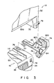
- Figs. 1 to 5 show a printer having an automatic sheet feeder according to an embodiment of the present invention, in which:
- a serial printer comprises printer body 10 and automatic sheet feeder 12 arranged on the printer body.
- Printer body 10 includes case 14.
- Case 14 includes upper wall 20 having paper discharge port 16 and cut sheet supply port 18, and rear wall 24 extending downward from a rear end of upper wall 20 in a substantially vertical direction and having continuous paper supply port 22.
- Printing mechanism 28, tractor 30, and the like are arranged in case 14.
- Printing mechanism 28 includes platen 26, both ends of which are supported by bearings 32. Platen 26 is located near paper discharge port 16 and cut sheet supply port 18, and horizontally extends.
- Printing mechanism 28 includes carriage 34 arranged to be movable along the axial direction of platen 26, and printing head 36 arranged on carriage 34 to oppose platen 26.
- Tractor 30 is located between continuous paper supply port 22 and platen 26 and transfers continuous paper 38 inserted from supply port 22 into case 14 toward platen 26.
- a pair of guide plates 40 for guiding continuous paper 38 are arranged between tractor 30 and platen 26.
- guide plate 42 for guiding a cut sheet, which is introduced from supply port 18 into case 14, to platen 26, a pair of friction rollers 44 and 45 capable of being urged against the outer surface of platen 26, and bail roller 46 for urging continuous paper against the outer surface of platen 26.
- Front cover 48 and soundproof cover 50 are detachably mounted on upper wall 20 to cover discharge port 16, respectively.
- reference numeral 51 denotes a plurality of separators horizontally extending backward from the rear end portion of upper wall 20. These separators serve to guide discharged continuous paper 38.
- Each separator 5 1 has an appropriate length so as to prevent printed continuous paper 38 from interfering with continuous paper supply port 22.
- Automatic sheet feeder 12 includes rectangular case 52, in which cut sheet feeding mechanism 54 and cut sheet stacking mechanism 56 are arranged.
- Feeding mechanism 54 has paper cassette 60 storing a plurality of cut sheets in a stacking state, separating pawl 61 arranged on paper cassette 60 to restrict feeding of the cut sheets, and feed roller 62, urged against the uppermost sheet of cut sheets 58 stacked on paper cassette 60, for feeding the cut sheets one by one.
- cut sheet stacking mechanism 56 includes stacker 64 for stacking printed cut sheets, a pair of discharge rollers 66 for transferring a cut sheet discharged from printer body 10 to stacker 64, and guide plates 68 for guiding the transfer of the cut sheet.
- Sheet feeder 12 is mounted on printer body 10 to be movable between the non-actuating position shown in Fig. 2 and the actuating position shown in Fig. 4. More specifically, as is shown in Figs. 1 to 4, a lower portion of case 52 of paper feeder 12 is obliquely cut on the rear end side thereof to form notched portion 52a. Support plates 70 vertically extend from the right and left ends of notched portion 52a, and hinge pins 72 horizontally extend outward from support plates 70, respectively. A pair of hinge members 74 are arranged on the both sides of the rear portion of upper wall 20 of printer body 10 at a predetermined interval therebetween. Hinge pins 72 of sheet feeder 12 are pivotally supported by hinge members 74. Each hinge member 74, as apparent from Figs.
- each hinge member 74 includes projecting portion 80 extending obliquely and upwardly from case 14.
- Projecting portion 80 is formed with support hole 82 in which hinge pin 72 is pivotally inserted.
- Support hole 82 has horizontal portion 82a and insertion portion 82b, which obliquely and upwardly extends from the left end of horizontal portion 82a and opens at the side wall of projecting portion 80.
- Hinge pin 72 is inserted into horizontal portion 82a through insertion portion 82b.
- sheet feeder 12 can pivot about hinge pins 72. Note that sheet feeder 12 can be detached from printer body 10 by pulling hinge pins 72 off from support holes 82 through insertion portions 82b, respectively.
- Each hinge member 74 includes stopper 84 extending inward.
- Sheet feeder 12 also includes right and left support arms 86 extending from the lower end of the front portion of case 52. When sheet feeder 12 is pivoted to the actuating position, these arms are respectively mounted on bearings 32 of platen 26, thereby supporting the sheet feeder.
- automatic sheet feeder 12 When continuous paper 38 is to be printed, automatic sheet feeder 12 is pivoted about hinge pins 72 to the non-actuating position and is kept at this position. Friction rollers 44 and 45 are released from a state wherein they are urged against platen 26. In this state, tractor 30 is driven. Continuous paper 38 supplied from supply port 22 into case 14 is transferred by tractor 30 in a direction indicated by arrow A, and guided by guide plate 40 to a position between platen 26 and printing head 36. Subsequently, continuous paper 38 is temporarily stopped in a state wherein the distal end of paper 38 is urged against the outer surface of platen 26 by bail roller 46. Then, printing head 36 mounted on carriage 34 is moved in the axial direction of platen 26, and one line is printed on continuous paper 38.
- continuous paper 38 is transferred by tractor 30 in the direction indicated by arrow A by a predetermined amount, and then the next line is printed on paper 38.
- the printed continuous paper is discharged outside case 14 through paper discharge port 14, guided to separators 51 sliding on upper wall 20 of case 14, and fed downward from the distal ends of separators 51. Since each separator 51 has a sufficient length for guiding the paper, the printed continuous paper is smoothly discharged without interfering with continuous paper to be introduced to supply port 22. Line printing of continuous paper 38 is repeated in the above-described manner.
- Automatic sheet feeder 12 pivoted to the non-actuating position is sufficiently spaced apart from paper discharge port 16, and hinge pins 72 are supported by hinge members 74 extending upward from upper wall 20 of printer body 10. Therefore, case 52 of sheet feeder 12 is kept to be sufficiently separated from upper wall 20 and separators 51 of case 14. Accordingly, no member, which interferes with discharging of the continuous paper, is located in a discharge path through which the printed continuous paper is transferred from paper discharge port 16 to the extending portions of separators 51, and hence the printed continuous paper can be smoothly discharged.
- bail roller 46 Prior to feeding of cut sheet 58, bail roller 46 is separated from platen 26 and friction rollers 44 and 45 are urged against the outer surface of platen 26 by a switching mechanism (not shown). Furthermore, continuous paper 38 set in tractor 30 is moved out of a path for the cut sheet, and transmission of a driving force to the tractor is stopped.
- feed roller 62 urged against the uppermost cut sheet among cut sheets 58 stacked in paper cassette 60 is rotated by a drive source (not shown) in a direction indicated by arrow B.
- uppermost cut sheet 58 is pushed out from cassette 60 toward printer body 10, passes over separating pawl 61 to be separated from the other cut sheets, and is fed to a position between platen 26 and friction rollers 44 and 45 through cut sheet supply port 18.
- feed roller 62 is stopped, and platen 26 is rotated in a direction indicated by arrow C.
- cut sheet 58 is transferred so that its distal end is introduced between guide plates 68 through a path between platen 26 and printing head 36.
- cut sheet 58 is transferred to a predetermined printing position in the above-described manner, printing head 36 together with carriage 34 is moved in the axial direction of platen 26.
- cut sheet 58 is printed by printing head 36 in units of lines. Every time each line is printed, platen 26 is rotated in the direction indicated by arrow C by a predetermined amount, thereby feeding the sheet.
- cut sheet 58 is introduced between discharge rollers 66 with being guided by guide plates 68, and transferred to stacker 64 upon rotation of discharge rollers 66 and stacked therein.
- the printer having the above-described arrangement includes the following advantages. Since automatic sheet feeder 12 is mounted on the printer body to be pivotal between the actuating and non-actuating positions, automatic feeding of continuous paper and cut sheets can be switched, without detaching sheet feeder 12 from the printer body, by a simple operation, i.e., pivoting sheet feeder 12. Further, no space is required for keeping detached automatic sheet feeder 12. When continuous paper is to be printed, automatic sheet feeder 12 is kept at a position out of the discharge path for the continuous paper, i.e., at the non-actuating position where discharging of the continuous paper is not interfered with at all. As a result, the continuous paper can be smoothly discharged.
- sheet feeder 12 is sufficiently separated from paper discharge port 16 of printer body 10, so that the continuous paper can be cut off near the printing position. Furthermore, since the discharged continuous paper does not pass through the inside of automatic sheet feeder 12, the continuous paper is not affected by a tension caused by discharge rollers 66. Consequently, a feed amount of continuous paper can be accurately controlled by tractor 30 and rotation of platen 26, and hence line-feed of the continuous paper during the printing mode can be accurately performed. As a result, high-density printing can be performed.
- automatic sheet feeder 12 fails or kept unused for a long period of time, it can be detached from printer body 10 by a simple operation, i.e., pulling hinge pins 72 off from support holes 82 of hinge members 74.
- sheet feeder 12 can be kept at the non-actuating position by support rod 88.
- one end of rod 88 is pivotally supported by case 52 of sheet feeder 12.
- the other end of rod 88 is fitted and positioned in recess 90 formed in upper wall 20 of printer body 10.
- support rod 88 is pivoted toward hinge pins 72 of sheet feeder 12 and housed between sheet feeder 12 and printer body 10.
- the automatic sheet feeder is pivotally arranged between the actuating and non-actuating positions.
- the automatic sheet feeder is not limited to the above arrangement, and may be supported by a link mechanism or the like to be linearly movable between the above two positions.
Landscapes
- Handling Of Sheets (AREA)
Applications Claiming Priority (2)
| Application Number | Priority Date | Filing Date | Title |
|---|---|---|---|
| JP61242689A JPS6395973A (ja) | 1986-10-13 | 1986-10-13 | プリンタ装置 |
| JP242689/86 | 1986-10-13 |
Publications (2)
| Publication Number | Publication Date |
|---|---|
| EP0264111A1 true EP0264111A1 (de) | 1988-04-20 |
| EP0264111B1 EP0264111B1 (de) | 1990-05-16 |
Family
ID=17092772
Family Applications (1)
| Application Number | Title | Priority Date | Filing Date |
|---|---|---|---|
| EP87114964A Expired - Lifetime EP0264111B1 (de) | 1986-10-13 | 1987-10-13 | Automatische Blattzuführung für einen Drucker |
Country Status (5)
| Country | Link |
|---|---|
| US (1) | US4854757A (de) |
| EP (1) | EP0264111B1 (de) |
| JP (1) | JPS6395973A (de) |
| KR (1) | KR900006500B1 (de) |
| DE (1) | DE3762716D1 (de) |
Cited By (4)
| Publication number | Priority date | Publication date | Assignee | Title |
|---|---|---|---|---|
| GB2221898A (en) * | 1988-08-20 | 1990-02-21 | Citizen Watch Co Ltd | Printer for use with a continuous form and cut sheets |
| GB2248226A (en) * | 1990-09-14 | 1992-04-01 | Brother Ind Ltd | Stocking printing sheets |
| EP0593220A3 (en) * | 1992-10-12 | 1994-06-29 | Brother Ind Ltd | Printer having continuous sheet supply mechanism and automatic cut sheet supply mechanism |
| EP0881087A1 (de) * | 1997-05-30 | 1998-12-02 | Ascom Monetel S.A. | Thermodrucker mit leichtem Druckpapierwechsel |
Families Citing this family (25)
| Publication number | Priority date | Publication date | Assignee | Title |
|---|---|---|---|---|
| USD318875S (en) | 1987-06-19 | 1991-08-06 | Nec Corporation | Sheet feeder for computer output printers |
| DE3727070A1 (de) * | 1987-08-11 | 1989-02-23 | Mannesmann Ag | Papierfuehrungsvorrichtung fuer bueromaschinen, insbesondere fuer matrixdrucker |
| USD322804S (en) | 1989-03-07 | 1991-12-31 | Citizen Watch Co., Ltd. | Printer |
| JPH02255355A (ja) * | 1989-03-30 | 1990-10-16 | Matsushita Electric Ind Co Ltd | 紙送り装置 |
| DE69014963T2 (de) * | 1989-04-14 | 1995-08-03 | Seiko Epson Corp | Elektrophotographisches Aufzeichnungsgerät. |
| JP2597261Y2 (ja) * | 1989-05-30 | 1999-07-05 | セイコーエプソン株式会社 | 印字装置 |
| US5037222A (en) * | 1989-08-29 | 1991-08-06 | Genicom Corporation | Printer and cartridge assembly therefor |
| EP0418793B1 (de) * | 1989-09-18 | 1996-01-17 | Canon Kabushiki Kaisha | Aufzeichnungsapparat |
| DE3934936A1 (de) * | 1989-10-17 | 1991-04-25 | Mannesmann Ag | Vorrichtung fuer den papiereinzug eines druckers, insbesondere eines matrix-druckers |
| US5141346A (en) * | 1990-06-28 | 1992-08-25 | Brother Kogyo Kabushiki Kaisha | Sheet feeder having automatic cut-sheet feed, continuous-form feed, and manual sheet insertion modes |
| JPH04189166A (ja) * | 1990-11-22 | 1992-07-07 | Tokyo Electric Co Ltd | プリンタ |
| US5141345A (en) * | 1991-04-15 | 1992-08-25 | Citizen Watch Co., Ltd. | Sheet discharge apparatus for printer |
| US5988809A (en) * | 1991-09-12 | 1999-11-23 | Canon Kabushiki Kaisha | Recording apparatus with system for stacking , supplying and guiding recording media |
| GB2260206B (en) * | 1991-09-27 | 1994-10-12 | Laurel Bank Machine Co | Sheet counting machine |
| JP2725123B2 (ja) * | 1991-11-22 | 1998-03-09 | ローレルバンクマシン株式会社 | シート計数機 |
| US5348407A (en) * | 1992-05-19 | 1994-09-20 | Hewlett-Packard Company | Snap-on control panel |
| DE4332575A1 (de) * | 1993-09-24 | 1995-03-30 | Esselte Meto Int Gmbh | Druckmaschine |
| SG55068A1 (en) * | 1993-10-29 | 1998-12-21 | Seiko Epson Corp | Printer |
| JP3014924B2 (ja) * | 1994-06-17 | 2000-02-28 | 有限会社ウイング設計 | 紙葉類計数方法及び装置 |
| US5553842A (en) * | 1994-10-17 | 1996-09-10 | Hewlett-Packard Company | Precision referencing/latching system for document separation and transport in a scanning unit |
| US5764384A (en) * | 1994-10-17 | 1998-06-09 | Hewlett-Packard Company | Integrated chassis for automatic document feeder in a scanning unit |
| US6022012A (en) * | 1998-03-12 | 2000-02-08 | Hewlett-Packard Company | Modular automatic document feeder for a flat bed input device |
| US6461282B1 (en) | 2000-02-09 | 2002-10-08 | Paul J. Fenelon | Dumbbell system |
| US7000914B2 (en) * | 2002-04-13 | 2006-02-21 | Hewlett-Packard Development Company, L.P. | Imaging methods and apparatus |
| JP5724410B2 (ja) * | 2011-01-31 | 2015-05-27 | セイコーエプソン株式会社 | 記録装置 |
Citations (2)
| Publication number | Priority date | Publication date | Assignee | Title |
|---|---|---|---|---|
| GB2156280A (en) * | 1984-03-09 | 1985-10-09 | Tokyo Electric Co Ltd | Automatic paper sheet supplying apparatus |
| US4570923A (en) * | 1984-12-19 | 1986-02-18 | Pitney Bowes Inc. | Conveying apparatus |
Family Cites Families (12)
| Publication number | Priority date | Publication date | Assignee | Title |
|---|---|---|---|---|
| US1417597A (en) * | 1921-05-23 | 1922-05-30 | Paul A Gallien | Paper-feeding device |
| US1923771A (en) * | 1927-04-13 | 1933-08-22 | Remington Typewriter Co | Typewriting machine |
| US2887208A (en) * | 1953-11-10 | 1959-05-19 | Judson S Cross | Sheet feeding attachment for typewriters |
| US4067566A (en) * | 1976-04-12 | 1978-01-10 | Feeder One, Inc. | Automatic stationery handling method and apparatus |
| US4341480A (en) * | 1979-12-26 | 1982-07-27 | General Electric Company | Feed mechanism for continuous and cut form paper |
| US4326815A (en) * | 1980-01-21 | 1982-04-27 | Ziyad Incorporated | Paper feeding apparatus and method for printing apparatus |
| DE3014430C2 (de) * | 1980-04-15 | 1984-08-23 | Nixdorf Computer Ag, 4790 Paderborn | Einrichtung zur schrittweisen Zuführung von Aufzeichnungsträgern an ein elektromechanisches Schreibwerk |
| JPS5973980A (ja) * | 1982-10-20 | 1984-04-26 | Hitachi Ltd | プリンタ装置 |
| US4522519A (en) * | 1982-11-29 | 1985-06-11 | Dubois R Clark | Apparatus and process for drop-feeding sheets to a typing or printing machine including separable paper clamping trays |
| US4606663A (en) * | 1983-11-29 | 1986-08-19 | Siemens Aktiengesellschaft | Switchable paper transport device for single sheets and continuous paper in printers |
| JPS60154143A (ja) * | 1984-01-25 | 1985-08-13 | Hitachi Denshi Ltd | 光沢面物体の検査方法 |
| IT1196758B (it) * | 1984-11-19 | 1988-11-25 | Olivetti & Co Spa | Alimentatore di supporti di stampa per una macchina per scrivere o simili macchine da ufficio |
-
1986
- 1986-10-13 JP JP61242689A patent/JPS6395973A/ja active Pending
-
1987
- 1987-10-13 EP EP87114964A patent/EP0264111B1/de not_active Expired - Lifetime
- 1987-10-13 US US07/107,413 patent/US4854757A/en not_active Expired - Fee Related
- 1987-10-13 KR KR1019870011331A patent/KR900006500B1/ko not_active Expired
- 1987-10-13 DE DE8787114964T patent/DE3762716D1/de not_active Expired - Lifetime
Patent Citations (2)
| Publication number | Priority date | Publication date | Assignee | Title |
|---|---|---|---|---|
| GB2156280A (en) * | 1984-03-09 | 1985-10-09 | Tokyo Electric Co Ltd | Automatic paper sheet supplying apparatus |
| US4570923A (en) * | 1984-12-19 | 1986-02-18 | Pitney Bowes Inc. | Conveying apparatus |
Cited By (7)
| Publication number | Priority date | Publication date | Assignee | Title |
|---|---|---|---|---|
| GB2221898A (en) * | 1988-08-20 | 1990-02-21 | Citizen Watch Co Ltd | Printer for use with a continuous form and cut sheets |
| GB2221898B (en) * | 1988-08-20 | 1992-08-05 | Citizen Watch Co Ltd | Printer for use with a continuous form and cut sheets |
| GB2248226A (en) * | 1990-09-14 | 1992-04-01 | Brother Ind Ltd | Stocking printing sheets |
| EP0593220A3 (en) * | 1992-10-12 | 1994-06-29 | Brother Ind Ltd | Printer having continuous sheet supply mechanism and automatic cut sheet supply mechanism |
| US5391008A (en) * | 1992-10-12 | 1995-02-21 | Brother Kogyo Kabushiki Kaisha | Printer having continuous sheet supply mechanism and automatic cut sheet supply mechanism |
| EP0881087A1 (de) * | 1997-05-30 | 1998-12-02 | Ascom Monetel S.A. | Thermodrucker mit leichtem Druckpapierwechsel |
| FR2763887A1 (fr) * | 1997-05-30 | 1998-12-04 | Ascom Monetel Sa | Imprimante thermique a remplacement aise de papier d'impression |
Also Published As
| Publication number | Publication date |
|---|---|
| DE3762716D1 (de) | 1990-06-21 |
| KR900006500B1 (ko) | 1990-09-03 |
| JPS6395973A (ja) | 1988-04-26 |
| EP0264111B1 (de) | 1990-05-16 |
| KR880004953A (ko) | 1988-06-27 |
| US4854757A (en) | 1989-08-08 |
Similar Documents
| Publication | Publication Date | Title |
|---|---|---|
| EP0264111B1 (de) | Automatische Blattzuführung für einen Drucker | |
| US5120040A (en) | Sheet media tray and mechanism for feeding media of two different sizes | |
| US7762546B2 (en) | Sheet conveying device and image recording apparatus including the sheet conveying device | |
| EP2042456B1 (de) | Blattzuführungsanordnung | |
| EP0776844B1 (de) | Vorrichtung zum Durchführen von Auzeichnungsträgern in Druckern | |
| KR100490079B1 (ko) | 용지 수납 장치, 용지 수납 장치가 제공된 용지 급송 장치및 화상 형성 장치 | |
| EP0879706A2 (de) | Aufzeichnungsgerät | |
| US7735822B2 (en) | Sheet cassette and information processing apparatus | |
| JP2005099289A (ja) | プリンタ装置 | |
| JP5830970B2 (ja) | 画像記録装置 | |
| EP0615939B1 (de) | Papierzufuhrgerät für ein Bildwiedergabegerät | |
| EP0844202B1 (de) | Ablage für Aufzeichnungsträger | |
| US5448268A (en) | Manual paper loading device | |
| JPH0123820Y2 (de) | ||
| JPH03297741A (ja) | 印刷機の給紙装置 | |
| JP3033243B2 (ja) | プリンタ | |
| JPH06100184A (ja) | 画像形成装置のトレイ装置 | |
| JPH081097Y2 (ja) | 印字装置 | |
| JPH0611968Y2 (ja) | 給紙装置 | |
| EP0752320A1 (de) | Drucker mit Einfuhrsystem von mehreren Endlospapierbahnen | |
| JPH06135577A (ja) | 画像形成装置の給紙装置 | |
| JP2699194B2 (ja) | 記録装置 | |
| JP2002283583A (ja) | インクジェット式記録装置 | |
| JPH04217530A (ja) | 給紙カセット | |
| JPH0553697B2 (de) |
Legal Events
| Date | Code | Title | Description |
|---|---|---|---|
| PUAI | Public reference made under article 153(3) epc to a published international application that has entered the european phase |
Free format text: ORIGINAL CODE: 0009012 |
|
| 17P | Request for examination filed |
Effective date: 19871110 |
|
| AK | Designated contracting states |
Kind code of ref document: A1 Designated state(s): DE FR GB |
|
| 17Q | First examination report despatched |
Effective date: 19890802 |
|
| GRAA | (expected) grant |
Free format text: ORIGINAL CODE: 0009210 |
|
| AK | Designated contracting states |
Kind code of ref document: B1 Designated state(s): DE FR GB |
|
| REF | Corresponds to: |
Ref document number: 3762716 Country of ref document: DE Date of ref document: 19900621 |
|
| ET | Fr: translation filed | ||
| PLBE | No opposition filed within time limit |
Free format text: ORIGINAL CODE: 0009261 |
|
| STAA | Information on the status of an ep patent application or granted ep patent |
Free format text: STATUS: NO OPPOSITION FILED WITHIN TIME LIMIT |
|
| 26N | No opposition filed | ||
| PGFP | Annual fee paid to national office [announced via postgrant information from national office to epo] |
Ref country code: GB Payment date: 19941004 Year of fee payment: 8 |
|
| PGFP | Annual fee paid to national office [announced via postgrant information from national office to epo] |
Ref country code: DE Payment date: 19941010 Year of fee payment: 8 |
|
| PGFP | Annual fee paid to national office [announced via postgrant information from national office to epo] |
Ref country code: FR Payment date: 19941011 Year of fee payment: 8 |
|
| PG25 | Lapsed in a contracting state [announced via postgrant information from national office to epo] |
Ref country code: GB Effective date: 19951013 |
|
| GBPC | Gb: european patent ceased through non-payment of renewal fee |
Effective date: 19951013 |
|
| PG25 | Lapsed in a contracting state [announced via postgrant information from national office to epo] |
Ref country code: FR Effective date: 19960628 |
|
| PG25 | Lapsed in a contracting state [announced via postgrant information from national office to epo] |
Ref country code: DE Effective date: 19960702 |
|
| REG | Reference to a national code |
Ref country code: FR Ref legal event code: ST |