EP0264123A2 - Torsionsschwingungsdämpfer - Google Patents
Torsionsschwingungsdämpfer Download PDFInfo
- Publication number
- EP0264123A2 EP0264123A2 EP87115031A EP87115031A EP0264123A2 EP 0264123 A2 EP0264123 A2 EP 0264123A2 EP 87115031 A EP87115031 A EP 87115031A EP 87115031 A EP87115031 A EP 87115031A EP 0264123 A2 EP0264123 A2 EP 0264123A2
- Authority
- EP
- European Patent Office
- Prior art keywords
- coil spring
- elastic member
- disposed
- rubber elastic
- vibration absorber
- Prior art date
- Legal status (The legal status is an assumption and is not a legal conclusion. Google has not performed a legal analysis and makes no representation as to the accuracy of the status listed.)
- Granted
Links
Images



Classifications
-
- F—MECHANICAL ENGINEERING; LIGHTING; HEATING; WEAPONS; BLASTING
- F16—ENGINEERING ELEMENTS AND UNITS; GENERAL MEASURES FOR PRODUCING AND MAINTAINING EFFECTIVE FUNCTIONING OF MACHINES OR INSTALLATIONS; THERMAL INSULATION IN GENERAL
- F16F—SPRINGS; SHOCK-ABSORBERS; MEANS FOR DAMPING VIBRATION
- F16F15/00—Suppression of vibrations in systems; Means or arrangements for avoiding or reducing out-of-balance forces, e.g. due to motion
- F16F15/10—Suppression of vibrations in rotating systems by making use of members moving with the system
- F16F15/12—Suppression of vibrations in rotating systems by making use of members moving with the system using elastic members or friction-damping members, e.g. between a rotating shaft and a gyratory mass mounted thereon
- F16F15/121—Suppression of vibrations in rotating systems by making use of members moving with the system using elastic members or friction-damping members, e.g. between a rotating shaft and a gyratory mass mounted thereon using springs as elastic members, e.g. metallic springs
- F16F15/123—Wound springs
- F16F15/1232—Wound springs characterised by the spring mounting
- F16F15/12326—End-caps for springs
- F16F15/12333—End-caps for springs having internal abutment means
Definitions
- the present invention relates to a torsional vibration absorber, and more specifically to a vibration absorber incorporated in a flywheel, clutch disk, or drive shaft system, in particular, in order to absorb torque fluctuation of a combustion engine.
- a prior-art absorber of this type comprises a drive plate connected to a drive source, a driven plate connected to a driven member, and resilient means disposed between these two plates, and these two plates are rotated relative to each other by resiliently compressing the resilient means.
- the above prior-art absorber is applied to a clutch disk for an automotive vehicle.
- resilient means disposed between the drive plate and the driven plate is composed of a coil spring disposed along a relative rotational direction and a compressive rubber elastic member loosely disposed within an inner cavity of the coil spring; a resin sheet having a dimeter larger than an external diameter of the compressive cushion rubber elastic member is fixed by strong bonding to both ends of the compressive rubber elastic member and disposed within said inner cavity of the coil spring; and a metallic seat is disposed at one end of the coil spring so as to be brought into contact with one of said resin sheets to compress the compressive rubber elastic member only in one of the relative rotational directions along which the both plates rotate.
- the coil spring when twisted in the positive direction, the coil spring is first compressed between the drive plate and the driven plate; secondly, the metallic seat pushed by the drive plate is brought into contact with the resin sheet to compress the compressive (cushion) rubber elastic member against the driven plate, so that a high torque is transmitted.
- the coil spring When twisted in the negative direction, since the torque is low, the coil spring is compressed only between the drive plate and the driven plate, and the cushion rubber elastic member is not compressed. Since the compressive (cushion) rubber elastic member is provided with resin sheets fixed on both the ends thereof, the rubber elastic member will not be forced to penetrate the space between drive plates (i.e., main-and subplates).
- the diameter of the resin sheet is determined to be larger than that of the compressed cushion rubber elastic member, it is possible to prevent the contact and the resultant abrasion between the coil spring and the cushion rubber elastic member.
- the metallic seat (retainer for the spring) is so provided as to compress the cushion rubber elastic member only in the positive (forward) rotational direction, an engagement margin is narrow and further the resin sheet will not be forced to penetrate the space between the main-and the subplates.
- no metallic seat is provided on the reverse rotational side, the circumferential space can be reduced, and therefore the plate strength will not be reduced. It is selfexplanatory that one of the metallic seats (conventionally two) for one window is eliminated.
- the elastic member can be arranged so as to serve as at a second (or further) range (stage) of the torsion characteristics curve.
- the resin sheets are light in weight and small in size so that the conventional window space is fully utilized without enlargement.
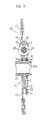
- Fig. 1 is an enlarged view showing a third spring and the rubber elastic member disposed within the windows of the hub flange shown in Fig. 2;
- Fig. 2 is a front view, partially broken showing a clutch disk of the present invention;
- Fig. 3 is a cross-sectional view taken along the line III-III of the clutch disk shown in Fig. 2;
- Fig. 4 is an enlarged view showing the cushion rubber elastic member and the periphery; and the Fig. 5 shows torsional characteristics diagram obtained by the clutch disk of the present invention.
- a drive plate 11 is composed of a main clutch plate 12 and a subplate 13. These main and subplates 12 and 13 are fixed by pins to form an integral body, and sandwiches a hub flange 21 via friction member 14, a thrust plate 15 and a disk spring 16 provided on the side surfaces of the hub flange 21, so as to be rotatable relative to a hub 20 serving as a driven plate.
- a cushion plate on both the surfaces of which friction plates 18 are fixed by rivets 17, respectively is fixed to the outer circumference of the main clutch plate 12 by rivets 19. These friction plates 18 are sandwiched between a flywheel (not shown) connected to a drive source such as an output shaft of an engine (not shown) and a pressure plate (not shown) of a clutch invention.
- a spline 20a fittable to a shaft (not shown) of a transmission is formed in an inner hole of the hub 20, and the flange 21 extending radially outwardly is formed integral with the hub 20 at the outer circumference thereof.
- the main and subplates 12 and 13 are arranged concentrically on both the sides of the flange 21, and a pin 14 for fixing these plates 12 and 13 penetrates a cutout 22 formed in the outer circumference of the flange. Therefore, the main and subplates 12 and 13 are rotatable relative to the hub 20 as long as the pin 14 is not in contact with the end surface of the cutout 22.
- a double resilient member composed of a first coil spring SP1 and a second coil spring SP2, respectively; while on the upper and lower windows, there are provided a third coil spring SP3 and a cushion rubber elastic member 25, respectively.
- a metallic seat (retainer) 28 is attached to one end of the third coil spring SP3.
- the metallic seat 28 comprises a cylindrical protrusion 28a and a flanged portion.
- the cylindrical protrusion protrudes in an inner cavity of the third coil spring SP3 for securing its aligned position with the spring SP3, while the flanged portion retains one end of the spring SP3 and with its opposite side abuts against the corresponding ends of the window 60.
- the cylindrical protrusion 28a has an end surface 28b so as to receive the resin sheet 26 to abut against one end 26a thereof when the spring SP3 is compressed. Further, there are provided clearances (circumferentially and axially of the resin sheets) in such a way that the unit comprised of the cushion rubber elastic member 25 and the resin sheets 26 is freely circumferentially movable within the inner cavity of the third coil spring SP3. An angular clearance ⁇ 2 is provided between the other (left) end of the window 40 and the sring SP3.
- the spring SP3 is secured without angular clearance within a corresponding window 60 of the main-and subplates 12 and 13 with only one end being retained via the metallic seat 28 and the other end being directly retained by the window 60.
- Angular clearances ⁇ 1 and ⁇ 1 ⁇ are similarly provided between the spring SP2 and a corresponding window of the hub flange 21.
- Fig. 5 shows the relationship between the relative rotational angle (e.g. torsional angle) and the torque, that is, a so-called torsional angle-torque characteristics curve under the above-mentioned operating conditions.
- the characteristics curve is linear between 0 and ⁇ 2 where the coil springs SP1 to SP3 are compressed, but nonlinear between ⁇ 2 and ⁇ 3 where the cushion rubber elastic member 25 is additionally compressed.
- the hysteresis characteristics are due to the friction plates 14 disposed between the main-and subplates 12 and 13 and the hub flange 21, and a friction damper composed of a thrust plate 15 and a dish plate spring 16.
- torque T2 at ⁇ 3 determined higher than an engine effective torque, torque will not reach T2 under the ordinary engine running conditions.
- the invention thus provides a torsional vibration absorber comprising: a drive plate connected to a drive source, a driven plate connected to a driven member, and an resilient means disposed between the two plates, the two plates being rotatable relative to each other by resiliently compressing the resilient means, wherein said resilient means comprises a coil spring disposed along a relative rotational direction thereof and a compressive rubber elastic member loosely disposed within an inner cavity of said coil spring; a resin sheet having a diameter larger than an external diameter of the compressive rubber elastic member is fixed by strong bonding to both ends of said cushion rubber elastic member and disposed within said inner cavity of said coil spring; and a metallic seat is disposed at one end of said coil spring so as to be brought into contact with one of said resin sheet to compress said compressive rubber elastic member only in one of the relative rotatational directions along which said both plates rotate.
- the rubber elastic member provides a non-linear torsion characteristics curve at second or further range.
Landscapes
- Engineering & Computer Science (AREA)
- General Engineering & Computer Science (AREA)
- Physics & Mathematics (AREA)
- Acoustics & Sound (AREA)
- Aviation & Aerospace Engineering (AREA)
- Mechanical Engineering (AREA)
- Mechanical Operated Clutches (AREA)
Applications Claiming Priority (2)
| Application Number | Priority Date | Filing Date | Title |
|---|---|---|---|
| JP157759/86U | 1986-10-15 | ||
| JP1986157759U JPH0326341Y2 (de) | 1986-10-15 | 1986-10-15 |
Publications (3)
| Publication Number | Publication Date |
|---|---|
| EP0264123A2 true EP0264123A2 (de) | 1988-04-20 |
| EP0264123A3 EP0264123A3 (en) | 1989-01-18 |
| EP0264123B1 EP0264123B1 (de) | 1991-04-17 |
Family
ID=15656707
Family Applications (1)
| Application Number | Title | Priority Date | Filing Date |
|---|---|---|---|
| EP87115031A Expired - Lifetime EP0264123B1 (de) | 1986-10-15 | 1987-10-14 | Torsionsschwingungsdämpfer |
Country Status (4)
| Country | Link |
|---|---|
| US (1) | US4789374A (de) |
| EP (1) | EP0264123B1 (de) |
| JP (1) | JPH0326341Y2 (de) |
| DE (1) | DE3769428D1 (de) |
Cited By (1)
| Publication number | Priority date | Publication date | Assignee | Title |
|---|---|---|---|---|
| CN110617279A (zh) * | 2018-06-19 | 2019-12-27 | 舍弗勒技术股份两合公司 | 离合器从动盘及离合器 |
Families Citing this family (12)
| Publication number | Priority date | Publication date | Assignee | Title |
|---|---|---|---|---|
| FR2614079B1 (fr) * | 1987-04-14 | 1992-04-10 | Valeo | Dispositif amortisseur de torsion a moyen elastique plus raide |
| US5558317A (en) * | 1994-01-26 | 1996-09-24 | General Motors Corporation | Volute springs adapted for torsional damper assemblies and method of manufacturing same |
| US6241614B1 (en) | 1998-03-30 | 2001-06-05 | Exedy Corporation | Clutch disk assembly having a two stage dampening mechanism having a further vibration dampening mechanism that functions in both stages of dampening |
| JP2000027945A (ja) * | 1998-07-14 | 2000-01-25 | Exedy Corp | ダンパー機構 |
| JP4455858B2 (ja) * | 2003-09-30 | 2010-04-21 | アイシン精機株式会社 | トーションダンパ |
| US7699708B2 (en) * | 2004-05-28 | 2010-04-20 | Oiles Corporation | Shaft coupling mechanism for electric power steering apparatus |
| US7568565B2 (en) * | 2004-08-17 | 2009-08-04 | Nes Technologies, Inc | Device, a system and a method for transferring vibrational energy |
| JP4577351B2 (ja) * | 2007-11-29 | 2010-11-10 | トヨタ自動車株式会社 | トルク変動吸収装置 |
| CN102341610B (zh) * | 2009-03-03 | 2013-11-13 | 利滕斯汽车合伙公司 | 以螺旋形卷绕离合器弹簧和弹簧圈减振器弹簧为特征的分离器 |
| JP5714385B2 (ja) * | 2011-03-31 | 2015-05-07 | アイシン精機株式会社 | トルク変動吸収装置 |
| JP5315377B2 (ja) * | 2011-04-14 | 2013-10-16 | 株式会社エクセディ | トルクコンバータ用のロックアップ装置 |
| JP6559399B2 (ja) * | 2014-02-27 | 2019-08-14 | 株式会社エクセディ | ダンパー装置 |
Family Cites Families (10)
| Publication number | Priority date | Publication date | Assignee | Title |
|---|---|---|---|---|
| JPS5042935Y2 (de) * | 1971-06-29 | 1975-12-08 | ||
| FR2371609A1 (fr) * | 1976-11-17 | 1978-06-16 | Ferodo Sa | Dispositif amortisseur de torsion notamment pour friction d'embrayage, en particulier de vehicule automobile |
| JPS5520930A (en) * | 1978-07-28 | 1980-02-14 | Aisin Seiki Co Ltd | Device for absorbing torque variation |
| FR2496210A1 (fr) * | 1980-12-16 | 1982-06-18 | Valeo | Dispositif amortisseur de torsion, notamment pour disque de friction d'embrayage de vehicule automobile |
| JPS57204319A (en) * | 1981-06-06 | 1982-12-15 | Aisin Seiki Co Ltd | Clutch disc |
| EP0070099B1 (de) * | 1981-07-14 | 1987-03-04 | Automotive Products Public Limited Company | Kupplungsscheibe für Reibungskupplung |
| FR2521243A1 (fr) * | 1982-02-09 | 1983-08-12 | Valeo | Dispositif amortisseur de torsion, en particulier friction d'embrayage, notamment pour vehicule automobile |
| JPS59200816A (ja) * | 1983-04-30 | 1984-11-14 | Aisin Chem Co Ltd | 捩り振動吸収装置 |
| EP0216476A1 (de) * | 1985-08-26 | 1987-04-01 | Borg-Warner Automotive, Inc. | Aufbau einer Kupplungsscheibe mit proportionaler Verzögerung der Reibung |
| JPS6275139A (ja) * | 1985-09-30 | 1987-04-07 | Aisin Seiki Co Ltd | 捩り振動吸収装置 |
-
1986
- 1986-10-15 JP JP1986157759U patent/JPH0326341Y2/ja not_active Expired
-
1987
- 1987-10-14 DE DE8787115031T patent/DE3769428D1/de not_active Expired - Lifetime
- 1987-10-14 US US07/108,090 patent/US4789374A/en not_active Expired - Lifetime
- 1987-10-14 EP EP87115031A patent/EP0264123B1/de not_active Expired - Lifetime
Cited By (2)
| Publication number | Priority date | Publication date | Assignee | Title |
|---|---|---|---|---|
| CN110617279A (zh) * | 2018-06-19 | 2019-12-27 | 舍弗勒技术股份两合公司 | 离合器从动盘及离合器 |
| CN110617279B (zh) * | 2018-06-19 | 2023-01-03 | 舍弗勒技术股份两合公司 | 离合器从动盘及离合器 |
Also Published As
| Publication number | Publication date |
|---|---|
| DE3769428D1 (de) | 1991-05-23 |
| US4789374A (en) | 1988-12-06 |
| EP0264123B1 (de) | 1991-04-17 |
| JPS6362648U (de) | 1988-04-25 |
| JPH0326341Y2 (de) | 1991-06-07 |
| EP0264123A3 (en) | 1989-01-18 |
Similar Documents
| Publication | Publication Date | Title |
|---|---|---|
| US5065642A (en) | Apparatus for absorbing torque variation | |
| US6209701B1 (en) | Damper disk assembly | |
| EP0264123B1 (de) | Torsionsschwingungsdämpfer | |
| GB2085552A (en) | Damper Disc | |
| KR100408803B1 (ko) | 댐퍼 기구 | |
| KR830002122B1 (ko) | 회전토오크 전달장치 | |
| CN103261731B (zh) | 扭转振动衰减装置 | |
| US6676525B2 (en) | Damper mechanism | |
| CN103238008A (zh) | 扭转振动衰减装置 | |
| JP2005106158A (ja) | トーションダンパ | |
| US6332843B1 (en) | Damper disk assembly | |
| US6488139B1 (en) | Damper mechanism | |
| US11555526B2 (en) | Torsion damping device with activatable friction device | |
| US6336867B1 (en) | Damper mechanism and damper disk assembly | |
| US6520306B2 (en) | Torsional damping device, especially for clutches | |
| JP3731236B2 (ja) | トーションダンパ | |
| US4651860A (en) | Clutch disk supported by a resin bushing | |
| JP3498348B2 (ja) | ダンパーディスク | |
| US20030045362A1 (en) | Damper mechanism | |
| JPH0139492B2 (de) | ||
| JP2000320614A (ja) | 動力伝達装置 | |
| JP3986266B2 (ja) | クラッチディスク組立体 | |
| GB2315533A (en) | Motor vehicle clutch plate | |
| JP2000205295A (ja) | ダンパ―ディスク組立体 | |
| JP2000205339A (ja) | 弾性フロ―ト体 |
Legal Events
| Date | Code | Title | Description |
|---|---|---|---|
| PUAI | Public reference made under article 153(3) epc to a published international application that has entered the european phase |
Free format text: ORIGINAL CODE: 0009012 |
|
| AK | Designated contracting states |
Kind code of ref document: A2 Designated state(s): DE FR GB |
|
| PUAL | Search report despatched |
Free format text: ORIGINAL CODE: 0009013 |
|
| AK | Designated contracting states |
Kind code of ref document: A3 Designated state(s): DE FR GB |
|
| 17P | Request for examination filed |
Effective date: 19890629 |
|
| 17Q | First examination report despatched |
Effective date: 19891004 |
|
| GRAA | (expected) grant |
Free format text: ORIGINAL CODE: 0009210 |
|
| AK | Designated contracting states |
Kind code of ref document: B1 Designated state(s): DE FR GB |
|
| ET | Fr: translation filed | ||
| REF | Corresponds to: |
Ref document number: 3769428 Country of ref document: DE Date of ref document: 19910523 |
|
| PLBE | No opposition filed within time limit |
Free format text: ORIGINAL CODE: 0009261 |
|
| STAA | Information on the status of an ep patent application or granted ep patent |
Free format text: STATUS: NO OPPOSITION FILED WITHIN TIME LIMIT |
|
| 26N | No opposition filed | ||
| REG | Reference to a national code |
Ref country code: GB Ref legal event code: IF02 |
|
| PGFP | Annual fee paid to national office [announced via postgrant information from national office to epo] |
Ref country code: DE Payment date: 20051006 Year of fee payment: 19 |
|
| PGFP | Annual fee paid to national office [announced via postgrant information from national office to epo] |
Ref country code: FR Payment date: 20051010 Year of fee payment: 19 |
|
| PGFP | Annual fee paid to national office [announced via postgrant information from national office to epo] |
Ref country code: GB Payment date: 20051012 Year of fee payment: 19 |
|
| PG25 | Lapsed in a contracting state [announced via postgrant information from national office to epo] |
Ref country code: DE Free format text: LAPSE BECAUSE OF NON-PAYMENT OF DUE FEES Effective date: 20070501 |
|
| GBPC | Gb: european patent ceased through non-payment of renewal fee |
Effective date: 20061014 |
|
| REG | Reference to a national code |
Ref country code: FR Ref legal event code: ST Effective date: 20070629 |
|
| PG25 | Lapsed in a contracting state [announced via postgrant information from national office to epo] |
Ref country code: GB Free format text: LAPSE BECAUSE OF NON-PAYMENT OF DUE FEES Effective date: 20061014 |
|
| PG25 | Lapsed in a contracting state [announced via postgrant information from national office to epo] |
Ref country code: FR Free format text: LAPSE BECAUSE OF NON-PAYMENT OF DUE FEES Effective date: 20061031 |