EP0264442B1 - Sequence d'impulsion intercalee pour l'acquisition d'images par resonance magnetique nucleaire (rmn) - Google Patents
Sequence d'impulsion intercalee pour l'acquisition d'images par resonance magnetique nucleaire (rmn) Download PDFInfo
- Publication number
- EP0264442B1 EP0264442B1 EP87903556A EP87903556A EP0264442B1 EP 0264442 B1 EP0264442 B1 EP 0264442B1 EP 87903556 A EP87903556 A EP 87903556A EP 87903556 A EP87903556 A EP 87903556A EP 0264442 B1 EP0264442 B1 EP 0264442B1
- Authority
- EP
- European Patent Office
- Prior art keywords
- time
- slices
- spin
- slice
- echo
- Prior art date
- Legal status (The legal status is an assumption and is not a legal conclusion. Google has not performed a legal analysis and makes no representation as to the accuracy of the status listed.)
- Expired - Lifetime
Links
- 238000001208 nuclear magnetic resonance pulse sequence Methods 0.000 title claims description 7
- 238000000034 method Methods 0.000 claims abstract description 41
- 238000005259 measurement Methods 0.000 claims abstract description 28
- 230000005415 magnetization Effects 0.000 claims description 18
- 238000005481 NMR spectroscopy Methods 0.000 claims description 14
- 238000002592 echocardiography Methods 0.000 claims description 10
- 238000003384 imaging method Methods 0.000 description 6
- 239000000463 material Substances 0.000 description 6
- 238000011084 recovery Methods 0.000 description 5
- 210000001519 tissue Anatomy 0.000 description 4
- 238000004458 analytical method Methods 0.000 description 3
- 230000000875 corresponding effect Effects 0.000 description 3
- 239000011159 matrix material Substances 0.000 description 3
- 230000003111 delayed effect Effects 0.000 description 2
- 238000013421 nuclear magnetic resonance imaging Methods 0.000 description 2
- 238000009738 saturating Methods 0.000 description 2
- 238000000264 spin echo pulse sequence Methods 0.000 description 2
- 230000015572 biosynthetic process Effects 0.000 description 1
- 238000004364 calculation method Methods 0.000 description 1
- 239000002131 composite material Substances 0.000 description 1
- 230000002596 correlated effect Effects 0.000 description 1
- 230000007812 deficiency Effects 0.000 description 1
- 238000003745 diagnosis Methods 0.000 description 1
- 229940079593 drug Drugs 0.000 description 1
- 239000003814 drug Substances 0.000 description 1
- 230000000694 effects Effects 0.000 description 1
- 230000014509 gene expression Effects 0.000 description 1
- 238000007689 inspection Methods 0.000 description 1
- 238000012986 modification Methods 0.000 description 1
- 230000004048 modification Effects 0.000 description 1
- 238000002601 radiography Methods 0.000 description 1
- 230000000630 rising effect Effects 0.000 description 1
- 238000005070 sampling Methods 0.000 description 1
- 210000004872 soft tissue Anatomy 0.000 description 1
- 238000003786 synthesis reaction Methods 0.000 description 1
Images




Classifications
-
- G—PHYSICS
- G01—MEASURING; TESTING
- G01R—MEASURING ELECTRIC VARIABLES; MEASURING MAGNETIC VARIABLES
- G01R33/00—Arrangements or instruments for measuring magnetic variables
- G01R33/20—Arrangements or instruments for measuring magnetic variables involving magnetic resonance
- G01R33/44—Arrangements or instruments for measuring magnetic variables involving magnetic resonance using nuclear magnetic resonance [NMR]
- G01R33/48—NMR imaging systems
- G01R33/483—NMR imaging systems with selection of signals or spectra from particular regions of the volume, e.g. in vivo spectroscopy
- G01R33/4833—NMR imaging systems with selection of signals or spectra from particular regions of the volume, e.g. in vivo spectroscopy using spatially selective excitation of the volume of interest, e.g. selecting non-orthogonal or inclined slices
- G01R33/4835—NMR imaging systems with selection of signals or spectra from particular regions of the volume, e.g. in vivo spectroscopy using spatially selective excitation of the volume of interest, e.g. selecting non-orthogonal or inclined slices of multiple slices
Definitions
- This invention relates to a method for providing an improved sequence of pulse control for Nuclear Magnetic Resonance Imaging. More particularly, the invention concerns an improved method of obtaining a multi-slice acquisition in which images from several slices are simultaneously acquired at preselected repetition times.
- Nuclear magnetic resonance has recently become extremely popular for the reproduction of images of the interior portions of the human body for diagnostic purposes. Although the examination of the interior body or a body portion having a variety of relatively soft tissues is the primary use for NMR techniques, they can also be utilized for circumstances whereby characteristics of tissues under inspection can be portrayed which are ordinarly not readily obtained using a radiography or other imaging techniques.
- the body under examination is subjected to one magnetic field which is usually constant in magnitude and another field which lies along at least one different vector from the first magnetic field.
- the second magnetic field is usually time-varying with the exact characteristic of each of these fields being a function of choice between any one of several available imaging techniques.
- the characteristics of each of these fields being a function of choice between any one of several available imaging techniques.
- the characteristics of the field energy must be pre-selected.
- one of the techniques called a spin-echo imaging utilizes a pre-selected repetition time T R , which is defined as the time between R' successive application of the same pulse sequence.
- TAU sampling delay time
- TAU sampling delay time
- TAU sampling delay time
- the first and second fields are applied to the tissue being examined in accordance with selected times and the results are detected and stored with the levels of the storage signals being correlated with their physical positions and with these levels being represented by a matrix of numbers.
- the numbers of the matrix are then displayed as a matrix of points of pixels which have different light or dark levels and the composite of these pixels forms an image having various contrasting areas.
- a physician utilizes the results of these contrasting areas within the image to observe and analyze a "slice" of the body of which the image was made from and, in a medical context, to thereby form a diagnosis.
- the degree of contrast between the various areas is a function of TR and ⁇ values which are selected before the measurement is made.
- the degree of contrast is also a function of the intrinsic properties of the materials including the net magnetization MC (which is proportional to Proton density), and the relaxation times T1 and T2. While one particular set of values for TR and ⁇ will produce an image with excellent contrast between certain sets of materials, it must be noted that this contrast will probably be insufficient between other types of materials being used. As a result of this varying contrast which depends upon the materials being used, it is necessary to make numerous sets of measurements with various values for TR and ⁇ . The images which result from these measurements use these different values of TR and T in order to adequately examine various tissues involved.
- the technique of the copending application provides a method in which a minimal number of measurements can be made and in which the data derived from these measurements is used to form synthetic images which include tissue contrast of a type which have been produced by measurements made with selected parameters such as TR and ⁇ value other than those which are actually used for the measurements.
- the intrinsic parameters are generally found by acquiring NMR signals for several different repetition times TR and applying them as a function of time.
- the value of the spin lattice relaxation time T1 is a measure of the curvature of a smooth curve which would most closely match the plotted values of measured signals. Because of the statistical uncertainty in the measured signals, there is uncertainty in the computed value of T1 which can be compensated for by taking measurements several times at repetition times initially used or by taking measurements at additional repetition times.
- Applicants' application WO 86/06843 provides a method and an apparatus for solving algorithms for the spin-relaxation time T1 and the spin-spin relaxation time T2 which are implemented as a sequence of passes through a digital video processor (DVP) which is reconfigured, between each pass, to perform the next desired mathematical step of the algorithm.
- DVP digital video processor
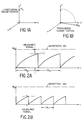
- M z illustrated in Figure 1, is never measured directly but is subjected to the flipping shown in Figure 1B.
- the length of the "flipped" magnetisation M xy immediately after the flip, equals that of M z prior to the flip. Because the measurement of T1 is actually the recovery time of the longitudinal magnetization after it has been altered away from an equilibrium position M O , the process naturally involves the initial setting of the M z at a known quantity such as 0 or -M O .
- the Figure 2A illustrates that the magnetization M z is initially set at a 0 value and then begins to change as a function of time toward asymptote M O . After some selected repetition time TR2 the signal is measured and the magnetization is returned to the starting initial value or 0 in the instance of Figure 2A.
- the Figure 2B illustrates a value of TR1 which is less than TR2 for purposes of providing a measured signal. It can be seen that the time period TR1 is less than TR2 so that the measured signal is less for a shorter time period or in other words the magnetization has not had as much opportunity to approach the asymptotic value as in the instance of Figure 2A which has a longer value for TR.
- FIG. 4A A single spin-echo treatment is shown in Figure 4A which involves a flipping of the longitudinal magnetization into the transverse plane in a manner similar to the showings of Figures 1A and 1B.
- This is a 90° flip and the starting value, as shown in Figure 4B, in the x-y plane for the magnetization M xy is equal to the longitudinal magnetization M z just prior to the flip.
- a 180° flip occurs which basically involves going from a plus value to an equivalent negative value, ergo 180°.
- a measured signal is obtained as shown in Figure 4B.
- the decay of the signal value from the starting value through the measured value at time TE is controlled by the exponential function EXP (- TE/T2) .
- FIGs 5A and 5B there is shown a graphic illustration of the application of the multiple spin-echo technique which utilizes for a single scanning time the various measured signals (4 in the instance of Figure 5) which are used to provide the various estimates for T2 at each of the four TE times of the multiple spin-echo technique.
- This provides for an increased number of measurements of T2 without an increased number of scans.
- the multiple spin-echo technique allows for the equivalent of several semi-independent measurements at each TR. With this increased number of measurements the net statistical precision which will be discussed below is improved and superior estimates of T2 can be had with no additional scanning time.
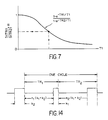
- the Figure 6 illustrates a three-dimensional graph which shows the relationship between the longitudinal magnetization M, the repetition times TR and the spin-echo times TE. Essentially, Figure 6 can be seen as an imposition of Figure 3 onto Figure 5B. It is important to note that T2 is not essential with respect to the calculation of T1 because as seen from Figure 7, for a single estimate of T1, the T2 is not a necessary function and is not a required quantity for the determination of T1.
- the existing deficiencies with respect to using a long TR MEMP and a short TR MEMP is that patient motion may occur between the time of the long TR MEMP and the short TR MEMP scan to thus cause images to not be registered. Additionally with the short TR MEMP scans the number of slices is potentially limited to 5, for example.
- the present invention proposes a method whereby the long and short TR data acquisition is interleaved to thereby reduce motion misregistration and potentially increase the number of slices imaged for the short TR.
- Multi-slice or multi-planar (MP) acquisitions are possible and are used in the prior art.
- Multiple spin-echo (MSE) or multi-echo (ME) are also used routinely as well as multi-TR or equivalently, multiple saturation recovery (MSR).
- MSR multiple saturation recovery
- multiple spin-echo and multiple saturation recovery have been combined in the prior art into a MSR-MRE sequence in which images from a single slice are collected for multiple TRs and multiple TEs.
- the first two have also been combined in order to yield a MEMP sequence with multiple echos from multiple slices for one TR.
- the present invention is a combination of MSR-ME-MP into one sequence.
- FIGURE 8 shows a standard multi-echo sequence for a single TR and a single slice.
- the signal which is plotted versus time indicates that data is being collected for that particular slice when the signal is high. That is, during the duration of the high state a 90° saturating pulse is applied as well as a 180° measurement pulse and the signal is then measured as indicated by the previous discussion with respect to the showing of the FIGURES 4A and 4B.
- the FIGURE 9 illustrates a single-slice multi-TR multi-echo sequence.
- the showing of FIGURE 9 indicates that the time between data acquisitions alternates between TR1 and TR2. That is, the data acquisitions for the short TR (TR1) and the long TR (TR2) images are interleaved.
- TR1 and TR2 The total scan time required to obtain images at TR1 and TR2 is the same as for the showing of FIGURE 8, however, due to the interleaving, any misregistration between the TR1 and TR2 is muted.
- the FIGURE 10 shows a multi-slice single-TR multi-echo sequence.
- the sequence for slice number 1 is identical to that of FIGURE 8 whereas the sequence for slice number 2 is identical to that for slice number 1 except that it is delayed by a time k so that the rising edge of the data acquisition period is simultaneous with the trailing edge for slice number 1.
- the alternate slices are selected by modulating the RF transmitted pulses.
- the signals for the slices are shown individually for purposes of clarity, although in reality, all of the signals shown are directed along the same channel. That is, the 90° and the 180° pulses for slice number 1 as well as those for slice number 2 and 3 are all directed along one transmitter channel. Likewise the detected signals from slices 1, 2, 3 etc., are all received from one channel. Thus it can be easily understood that two or more slices cannot overlap. From an analysis of the FIGURE 10 it is obvious that the maximum number of slices N s1 which can be obtained is equal to TR/k. That is, if TR is, for example, equal to 700 milliseconds and if k is 100 milliseconds, then N s1 is 7.
- FIGURES 11 and 12 show a multi-slice multi-TR multi-echo pulse sequence.
- the FIGURE 11 illustrates a sequence which is accomplished by first drawing the sequence for slice number 1 which is the same as that shown in FIGURE 9 and then beginning the sequence for slice number 2 delayed by an interval k. Such a delay is similar to the delay of the single-TR multi-slice case of FIGURE 10.
- the sequence for slice number 3 in FIGURE 11 follows an additional k period later. At that time the second pulse for slice number 1 is then applied.
- Having the three slices as shown in FIGURE 11 may appear to indicate that only three slices are possible with this approach for the given value of k, TR1 and TR2 used in this example.
- an analysis of the FIGURE 11 indicates that only 6 of the available 10 periods k have been used and thus the sequence shown in FIGURE 11 does not make full use of the available time.
- the method can be further generalized to the case in which the time interval required for readout is different for the two TR times used. That is, an interval k1 is used in conjunction with TR1 and k2 (not equal to K1) is used with TR2. Recall that k is the time required for the 90° saturating pulse, the 180° refocusing pulse, and the readout period of the spin-echo signal. Additionally, the 180° pulse and readout portion of the interval can be repeated for as many times as there are echoes in a multiple spin-echo sequence.
- One situation in which different k periods would be used is the acquisition of one number of spin-echoes at TR1 and a different number at TR2.
- the duration of the k interval is 25 msec longer than the time of the last spin-echo acquired in a spin-echo sequence. If for TR1 a single echo were acquired at 25 msec, then k1 would be 50 msec. If for TR2 spin-echoes were acquired at 25, 50, and 75 msec, then k2 would be 100 msec.
- 100% efficiency means that at all times a 90°-180°-readout interval is being applied to some slice.
- the objective of the arranging of the data intervals is to acquire data for as many slices as possible within the time available. If the two TR times used are TR1 and TR2, then the total repetition time is TR1 + TR2. If for one slice during one total repetition, data is read out from the TR1 sequence in an interval of duration k1, and from the TR2 sequence in an interval k2 then the total interval duration for that slice is k1 + k2.
- Figure 14 is a plot versus time of one complete cycle of the data interval signal for an arbitrary slice using the proposed technique. AT the end of the plot the cycle would repeat itself.
- the times TR1 and TR2 are defined as shown.
- k1 is the interval duration at the end of the TR1 recovery time and k2 is the interval at the end of the TR2 time as shown.
- the period preceding the k1 pulse should be an integral number of (k1 + k2) intervals.
- TR2 - k2 n2(k1 + k2) (3) where n2 is an integer.
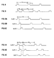
- k1 and k2 are the data intervals for TR1 and TR2 and h is the greatest common divisor of k1 and k2. That is, h is the largest number that can get divided into k1 and k2 an integral number of times. For example, if k1 is 40 msec and k2 is 60 msec, then h is 20 msec. Then, let m1 equal k1/h and m2 be k2/h; in this example m1 is 2 and m2 is 3.
- the assignment of intervals begins by first considering a plot of length TR1 + TR2 separated into intervals of length h as shown in Figure 15A. Next categorize intervals of length k2 and k1 in alternating fashion. What this means in Figure 15B is that the first m2 intervals of length h become the first k2 interval. The next m1 h intervals become a k1 interval, etc., the k1 and k2 assignment being an alternating process.
- k2 is 3 h intervals wide and k1 2 h intervals wide.
- the assignment of intervals for the first slice begins. It is desired to assign a k1 and k2 interval to it such that the TR times between these intervals are TR1 and TR2. As shown in Figure 15C the first k2 interval available is assigned to this slice. At a time TR1 - k1 after the end of the k2 interval the k1 interval for this slice begins. As seen, the time from the end of the assigned k2 interval to the end of the k1 interval is equal to TR1 as desired. Since the process will repeat cyclically as shown to the right of the dashed vertical line in Figure 15, it is clear that from the end of the assigned k1 interval to the end of the assigned k2 interval is time TR2, again as desired.
- a k2 and k1 interval can be assigned to each slice, the times between these intervals are the desired TR1 and TR2, and that all k1 and k2 intervals are assigned. This last statement is equivalent to saying that this assignment of intervals is 100% efficient. At all times in the total TR1 + TR2 interval, a k1 or k2 intervall is assigned to some slice.
- a long and short TR data acquisition is interleaved, which subsequently reduces a motion misregistration and potentially increases the number of slices which can be imaged for the short TR.
- one method of interleaving the MEMP acquisition for two values of TR has been shown, there are other methods and algorithms which could be used, as long as the essential concept of providing readouts at all possible times is maintained which requires that a value for each of TR1 and TR2 be an odd multiple of the data acquisition interval T r .
Landscapes
- Physics & Mathematics (AREA)
- Optics & Photonics (AREA)
- Spectroscopy & Molecular Physics (AREA)
- High Energy & Nuclear Physics (AREA)
- Condensed Matter Physics & Semiconductors (AREA)
- General Physics & Mathematics (AREA)
- Magnetic Resonance Imaging Apparatus (AREA)
Abstract
Claims (7)
- Méthode améliorée de balayage à résonance magnétique nucléaire (RMN) par laquelle des images provenant de tranches multiples, à des temps de répétition multiples TR et à des temps d'écho multiples TE sont obtenues par un balayage unique d'un corps, comprenant les étapes de :- soumission dudit corps à des champs magnétiques conformément à une technique RMN utilisant une séquence d'impulsions à échos de spin multiples et à tranches multiples, à une pluralité (n) de temps de répétition d'impulsion TR(n) différents, prédéterminés et mémorisés;- mesure d'une pluralité d'ensembles de signaux dans laquelle chacun desdits signaux correspond à une desdites tranches multiples, dans laquelle chaque signal de chacun desdits ensembles correspond à chacun de ladite pluralité de temps de répétition d'impulsion TR(n) prédéterminés mémorisés, et dans laquelle chaque signal de chacun desdits ensembles commence à un temps correspondant de ladite pluralité de temps de répétition d'impulsion.
- Méthode selon la revendication 1, dans laquelle la longueur de chacune desdites mesures de chacun desdits signaux dudit ensemble de signaux est un intervalle de temps k prédéterminé.
- Méthode selon la revendication 1, dans laquelle ladite pluralité de temps de répétition d'impulsion prédéterminés mémorisés est égale à deux.
- Méthode selon la revendication 1, dans laquelle la longueur du temps de mesure de chaque signal de chacun desdits ensembles est définie comme le temps requis pour basculer sélectivement l'aimantation dans le plan transversal et pour lire la valeur de l'aimantation après le basculement, dans laquelle la longueur de mesure de chaque ensemble (m) est constante, et dans laquelle le nombre maximal de tranches desdites tranches multiples est égal à Σ TR(n)/(m).
- Méthode selon la revendication 1, dans laquelle la longueur du temps de mesure de chacun desdits ensembles est définie comme le temps requis pour effectuer une séquence sélective de 90°- sélective de 180°- de lecture, dans laquelle la séquence sélective de 180° et de lecture peut être répétée dans un intervalle particulier un nombre de fois égal au nombre d'échos du spin pour chacun de ladite pluralité de temps de répétition d'impulsion différents prédéterminés mémorisés, dans laquelle la longueur de mesure de chaque ensemble (m) est constante, et dans laquelle le nombre maximal de tranches desdites tranches multiples est égal à Σ TR(n)/(m).
- Méthode selon la revendication 1, dans laquelle le nombre d'échos du spin est le même pour chacun de ladite pluralité de temps de répétition d'impulsion prédéterminés.
- Méthode selon la revendication 1, dans laquelle le nombre d'échos du spin pour un desdits temps de répétition d'impulsion prédéterminés n'est pas égal au nombre d'échos du spin pour les autres desdits intervalles de temps prédéterminés.
Applications Claiming Priority (2)
| Application Number | Priority Date | Filing Date | Title |
|---|---|---|---|
| US06/859,693 US4717879A (en) | 1986-05-05 | 1986-05-05 | Pulse sequence for NMR image acquisition |
| US859693 | 2001-05-17 |
Publications (3)
| Publication Number | Publication Date |
|---|---|
| EP0264442A1 EP0264442A1 (fr) | 1988-04-27 |
| EP0264442A4 EP0264442A4 (fr) | 1990-06-27 |
| EP0264442B1 true EP0264442B1 (fr) | 1994-02-16 |
Family
ID=25331516
Family Applications (1)
| Application Number | Title | Priority Date | Filing Date |
|---|---|---|---|
| EP87903556A Expired - Lifetime EP0264442B1 (fr) | 1986-05-05 | 1987-05-05 | Sequence d'impulsion intercalee pour l'acquisition d'images par resonance magnetique nucleaire (rmn) |
Country Status (6)
| Country | Link |
|---|---|
| US (1) | US4717879A (fr) |
| EP (1) | EP0264442B1 (fr) |
| JP (1) | JPH01501286A (fr) |
| DE (1) | DE3789086D1 (fr) |
| IL (1) | IL82418A0 (fr) |
| WO (1) | WO1987007029A1 (fr) |
Families Citing this family (14)
| Publication number | Priority date | Publication date | Assignee | Title |
|---|---|---|---|---|
| DE3631039A1 (de) * | 1986-09-12 | 1988-03-24 | Philips Patentverwaltung | Kernspintomographieverfahren und kernspintomograph zur durchfuehrung des verfahrens |
| JPH01148250A (ja) * | 1987-12-04 | 1989-06-09 | Hitachi Ltd | 磁気共鳴検査装置 |
| NL8703127A (nl) * | 1987-12-24 | 1989-07-17 | Philips Nv | Werkwijze en inrichting voor het genereren van vervlochten multiple-slice en multiple-echo pulssequenties voor mri. |
| US4851778A (en) * | 1988-12-15 | 1989-07-25 | The Regents Of The University Of California | Enhanced S/N MRI for short TR nutation sequences |
| US4986272A (en) * | 1989-08-09 | 1991-01-22 | Mayo Foundation For Medical Education And Research | NMR imaging with variable repetition |
| US5237273A (en) * | 1991-05-22 | 1993-08-17 | General Electric Company | Interleaved acquisition of multi-slice NMR data |
| JPH0556944A (ja) * | 1991-08-29 | 1993-03-09 | Toshiba Corp | 磁気共鳴イメージング装置 |
| JPH0763460B2 (ja) * | 1992-02-28 | 1995-07-12 | 株式会社日立メディコ | 磁気共鳴イメージング装置 |
| US5406203A (en) * | 1992-08-10 | 1995-04-11 | The Trustees Of Columbia University In The City Of New York | Methods of multislice acquisition for magnetic resonance imaging |
| JPH1066684A (ja) * | 1996-08-28 | 1998-03-10 | Hitachi Medical Corp | 磁気共鳴イメージング装置 |
| US6081117A (en) * | 1997-08-11 | 2000-06-27 | Panacea Medical Laboratories | Noise modulation for open access and remotely positioned MRI |
| CA2341812A1 (fr) * | 2000-03-24 | 2001-09-24 | National Research Council Of Canada | Imagerie spectroscopique par resonnance magnetique avec duree de repetition variable et temps d'acquisition de donnees variable |
| DE10123772B4 (de) * | 2001-05-16 | 2005-12-01 | Bruker Biospin Mri Gmbh | Verfahren zur Erzeugung von ortskodierten Messsignalen |
| CN114076913B (zh) * | 2020-08-19 | 2024-05-17 | 西门子(深圳)磁共振有限公司 | 一种前瞻性采集校正序列触发的磁共振成像方法和装置 |
Family Cites Families (4)
| Publication number | Priority date | Publication date | Assignee | Title |
|---|---|---|---|---|
| JPS5946546A (ja) * | 1982-09-09 | 1984-03-15 | Yokogawa Hokushin Electric Corp | 核磁気共鳴による検査方法及び検査装置 |
| JPS5985651A (ja) * | 1982-11-08 | 1984-05-17 | 株式会社東芝 | 診断用核磁気共鳴装置 |
| US4549140A (en) * | 1983-06-03 | 1985-10-22 | General Electric Company | Method utilizing combined, interleaved pulse sequences for reducing motion artifacts in computed T1,T2 and M0 NMR imaging |
| GB2148013B (en) * | 1983-10-12 | 1988-02-03 | Yokogawa Electric Corp | Nuclear magnetic resonance imaging |
-
1986
- 1986-05-05 US US06/859,693 patent/US4717879A/en not_active Expired - Fee Related
-
1987
- 1987-05-05 DE DE87903556T patent/DE3789086D1/de not_active Expired - Lifetime
- 1987-05-05 WO PCT/US1987/001019 patent/WO1987007029A1/fr not_active Ceased
- 1987-05-05 JP JP62503177A patent/JPH01501286A/ja active Pending
- 1987-05-05 EP EP87903556A patent/EP0264442B1/fr not_active Expired - Lifetime
- 1987-05-05 IL IL82418A patent/IL82418A0/xx not_active IP Right Cessation
Also Published As
| Publication number | Publication date |
|---|---|
| JPH01501286A (ja) | 1989-05-11 |
| WO1987007029A1 (fr) | 1987-11-19 |
| EP0264442A1 (fr) | 1988-04-27 |
| EP0264442A4 (fr) | 1990-06-27 |
| US4717879A (en) | 1988-01-05 |
| IL82418A0 (en) | 1987-11-30 |
| DE3789086D1 (de) | 1994-03-24 |
Similar Documents
| Publication | Publication Date | Title |
|---|---|---|
| Redpath et al. | Use of a double inversion recovery pulse sequence to image selectively grey or white brain matter | |
| US4734646A (en) | Method for obtaining T1-weighted and T2-weighted NMR images for a plurality of selected planes in the course of a single scan | |
| US4641095A (en) | Determination of T1 relaxation times used in automated nuclear magnetic resonance image synthesis | |
| US4665367A (en) | Multiplexed magnetic resonance imaging of volumetric regions | |
| US4698592A (en) | MRI of chemical shift spectra within limited inner volume | |
| US7917190B2 (en) | Image acquisition and reconstruction method for functional magnetic resonance imaging | |
| US4901020A (en) | Pulse sequence for operating a nuclear magnetic resonance tomography apparatus for producing images with different T2 contrast | |
| JP3973733B2 (ja) | 核磁気共鳴撮影装置 | |
| JPH11216129A (ja) | 傾斜およびスピンエコー(grase)イメージングを用いた超高速多重セクション全身mri | |
| US4717879A (en) | Pulse sequence for NMR image acquisition | |
| US5537039A (en) | Virtual frequency encoding of acquired NMR image data | |
| EP0127850A2 (fr) | Procédé utilisant des séquences combinées d'impulsions entrelacées pour réduire les artefacts de mouvement dans un procédé d'imagerie par résonance magnétique nucléaire des valeurs calculées de T1,T2 et M0 | |
| US4604579A (en) | Method and apparatus for enhanced T1 NMR measurements using repetition intervals TR related to one another by integer multiples | |
| US6933720B2 (en) | Sequence preconditioning for ultra-fast magnetic resonance imaging | |
| US5043665A (en) | Magnetic resonance imaging system | |
| US4918386A (en) | Method for simultaneously obtaining three-dimensional NMR angiograms and stationary tissue NMR images | |
| US5079505A (en) | Method in the form of a pulse sequence for fast calculation of images of the fat and water distribution in an examination subject on the basis of nuclear magnetic resonance | |
| US4837513A (en) | MRI using asymmetric RF nutation pulses and asymmetric synthesis of complex conjugated SE data to reduce TE and T2 decay NMR spin echo responses | |
| US7576535B2 (en) | Multi-compartment separation in magnetic resonance using transient steady-state free precession imaging | |
| US5406203A (en) | Methods of multislice acquisition for magnetic resonance imaging | |
| GB2261954A (en) | MRI method with increased z-axis slice resolution | |
| US6097185A (en) | Magnetic resonance imaging apparatus | |
| Hickey et al. | A method for the clinical measurement of relaxation times in magnetic resonance imaging | |
| US4855679A (en) | Magnetic resonance studies of restricted volumes | |
| DE3751771T2 (de) | Methode zur Rauschunterdrückung in magnetischen Kernresonanzbildern |
Legal Events
| Date | Code | Title | Description |
|---|---|---|---|
| PUAI | Public reference made under article 153(3) epc to a published international application that has entered the european phase |
Free format text: ORIGINAL CODE: 0009012 |
|
| 17P | Request for examination filed |
Effective date: 19871214 |
|
| AK | Designated contracting states |
Kind code of ref document: A1 Designated state(s): CH DE FR GB LI NL SE |
|
| A4 | Supplementary search report drawn up and despatched |
Effective date: 19900627 |
|
| 17Q | First examination report despatched |
Effective date: 19921016 |
|
| GRAA | (expected) grant |
Free format text: ORIGINAL CODE: 0009210 |
|
| AK | Designated contracting states |
Kind code of ref document: B1 Designated state(s): CH DE FR GB LI NL SE |
|
| PG25 | Lapsed in a contracting state [announced via postgrant information from national office to epo] |
Ref country code: SE Effective date: 19940216 Ref country code: NL Effective date: 19940216 Ref country code: LI Effective date: 19940216 Ref country code: FR Free format text: THE PATENT HAS BEEN ANNULLED BY A DECISION OF A NATIONAL AUTHORITY Effective date: 19940216 Ref country code: DE Effective date: 19940216 Ref country code: CH Effective date: 19940216 |
|
| REF | Corresponds to: |
Ref document number: 3789086 Country of ref document: DE Date of ref document: 19940324 |
|
| PG25 | Lapsed in a contracting state [announced via postgrant information from national office to epo] |
Ref country code: GB Effective date: 19940516 |
|
| REG | Reference to a national code |
Ref country code: CH Ref legal event code: PL |
|
| EN | Fr: translation not filed | ||
| NLV1 | Nl: lapsed or annulled due to failure to fulfill the requirements of art. 29p and 29m of the patents act | ||
| PLBE | No opposition filed within time limit |
Free format text: ORIGINAL CODE: 0009261 |
|
| STAA | Information on the status of an ep patent application or granted ep patent |
Free format text: STATUS: NO OPPOSITION FILED WITHIN TIME LIMIT |
|
| GBPC | Gb: european patent ceased through non-payment of renewal fee |
Effective date: 19940516 |
|
| 26N | No opposition filed |