EP0265174A2 - Lingotières pour la coulée continue - Google Patents
Lingotières pour la coulée continue Download PDFInfo
- Publication number
- EP0265174A2 EP0265174A2 EP87309112A EP87309112A EP0265174A2 EP 0265174 A2 EP0265174 A2 EP 0265174A2 EP 87309112 A EP87309112 A EP 87309112A EP 87309112 A EP87309112 A EP 87309112A EP 0265174 A2 EP0265174 A2 EP 0265174A2
- Authority
- EP
- European Patent Office
- Prior art keywords
- mould
- thermal barrier
- interior surface
- barrier layer
- metal
- Prior art date
- Legal status (The legal status is an assumption and is not a legal conclusion. Google has not performed a legal analysis and makes no representation as to the accuracy of the status listed.)
- Withdrawn
Links
Images


Classifications
-
- B—PERFORMING OPERATIONS; TRANSPORTING
- B22—CASTING; POWDER METALLURGY
- B22D—CASTING OF METALS; CASTING OF OTHER SUBSTANCES BY THE SAME PROCESSES OR DEVICES
- B22D11/00—Continuous casting of metals, i.e. casting in indefinite lengths
- B22D11/10—Supplying or treating molten metal
-
- B—PERFORMING OPERATIONS; TRANSPORTING
- B22—CASTING; POWDER METALLURGY
- B22D—CASTING OF METALS; CASTING OF OTHER SUBSTANCES BY THE SAME PROCESSES OR DEVICES
- B22D11/00—Continuous casting of metals, i.e. casting in indefinite lengths
- B22D11/04—Continuous casting of metals, i.e. casting in indefinite lengths into open-ended moulds
- B22D11/045—Continuous casting of metals, i.e. casting in indefinite lengths into open-ended moulds for horizontal casting
-
- B—PERFORMING OPERATIONS; TRANSPORTING
- B22—CASTING; POWDER METALLURGY
- B22D—CASTING OF METALS; CASTING OF OTHER SUBSTANCES BY THE SAME PROCESSES OR DEVICES
- B22D11/00—Continuous casting of metals, i.e. casting in indefinite lengths
- B22D11/04—Continuous casting of metals, i.e. casting in indefinite lengths into open-ended moulds
- B22D11/045—Continuous casting of metals, i.e. casting in indefinite lengths into open-ended moulds for horizontal casting
- B22D11/047—Means for joining tundish to mould
-
- B—PERFORMING OPERATIONS; TRANSPORTING
- B22—CASTING; POWDER METALLURGY
- B22D—CASTING OF METALS; CASTING OF OTHER SUBSTANCES BY THE SAME PROCESSES OR DEVICES
- B22D11/00—Continuous casting of metals, i.e. casting in indefinite lengths
- B22D11/04—Continuous casting of metals, i.e. casting in indefinite lengths into open-ended moulds
- B22D11/045—Continuous casting of metals, i.e. casting in indefinite lengths into open-ended moulds for horizontal casting
- B22D11/047—Means for joining tundish to mould
- B22D11/0475—Means for joining tundish to mould characterised by use of a break ring
Definitions
- This invention relates to molds for the continuous, horizontal casting of metallic materials and processes for using the molds.
- Metals e.g., steel, nickel, or iron
- the continuous casting of molten metal is a particularly advantageous means to form metal into forms useful for further processing.
- the molten metal is passed through a mold which shapes the metal and in which solidification commences.
- the continuous casting processes fall into one of two classes, a vertical casting process or a horizontal casting process.
- the horizontal casting process offers an alternative.
- molten metal in a tundish is passes through a lower portion of the tundish and into a horizontally-oriented mold in which the solidification of the stock commences.
- the stock is withdrawn from the mold, usually with an oscillating pulling to facilitate the movement of the stock in the mold. Since the operation is horizontal, the capital requirements and operational problems associated with the vertical casting processes are not incurred.
- molten metal may pass into any crevices between the tundish and mold and solidify, and these solids can cause scoring of the surface of the stock and may even induce structrual weaknesses in the stock. Also, chipping of the solid may occur and pass into the stock being produced, resulting in damage and imperfections in the stock as well as the mold.
- the break ring typically fits in the interior of the mold at its inlet end and forms a ring of smaller internal dimensions than the interior perimeter of the mold.
- the break ring is formed of a low heat conductivity ceramic having a relatively smooth surface.
- the break ring is composed of boron nitride. The break ring must be carefully machined to close tolerances to fit the dimensions of the mold.
- the break ring serves to provide insulation between the tundish opening (or nozzle) and the mold, and aids in defining where the skin solidification of the stock occurs.
- the metal may be molten when it contacts the break ring and commences solidification as it approaches or contacts the mold.
- problems with leakage of molten metal into crevices with subsequent solidification can be virtually avoided.
- the oscillating movement of the stock as it is pulled from the mold, together with the smaller cross-section opening formed by the break ring and the large cross-section opening of the mold can lead to the formation of what is termed as witness marks, that is, marks coinciding with the pushing of solidified metal surface back into the molten metal flowing from the break ring.
- witness marks that is, marks coinciding with the pushing of solidified metal surface back into the molten metal flowing from the break ring.
- thermal gradients and differentials in expansion can lead to the damage of the break ring and adversely affect the quality of the stock.
- break rings must be carefully machined to fit the mold. Because of the tight tolerances that must be met in fitting the break ring to the mold and the machining costs, molds are usually of limited configurations such as circular, square or rectangular in cross section. Long, narrow molds, for instance, can result in a bowing or breaking in use of the break ring and untoward seepage of molten metal. Hence, the size and cross-sectional configuration of the stock are limited to, e.g., billets, or blooms, and significant energy must be expended to work the stock into the sought shape such as an I-beam or plate material.
- moulds for the continuous horizontal casting of ferrous metals which do not depend upon the fitting of a separate break ring into a mould, yet are able to provide acceptable quality stock.
- the moulds can provide stock with reduced, and sometimes substantially eliminated, witness mark effects.
- moulds can be readily provided that are suitable for the continuous horizontal casting of near net shape stock which is of acceptable quality.
- a mould suitable for the continuous horizontal casting of metal to form shaped stock which comprises a mould body of heat conductive metal which defines by its interior surface a mould cavity having a transverse cross-sectional configuration approximating the cross-section of the shaped stock and which is adapted to contact coolant for indirect heat exchange from the interior surface of the mould, the mould also defining an end plate continuous with the interior surface of the mould, and a thermal barrier layer integral with the mould of at least that portion of the end plate of the mould that is adjacent the interior surface of the mould, which thermal barrier layer is adapted to contact a nozzle of a tundish to supply molten ferrous metal to the mould, the thermal barrier layer having sufficient thickness to prevent the solidification of the ferrous metal adjacent to the nozzle.
- the present invention also provides a process for the continuous horizontal casting of metal using the mould of the present invention.
- the mould comprises an interior surface, an end surface adapted to contact a nozzle through which molten metal passes and on at least that portion of the end surface adjacent to the interior surface, an integral thermal barrier of sufficient thickness to maintain the metal first contacting the thermal barrier substantially molten.
- the thermal barrier may comprise any suitably applied ceramic thermal barrier coating that is able to withstand the high temperatures associated with the molten metal and is not chemically attacked by the molten metal.
- the coating may provide a cross-section substantially the same as that of the mould and can thereby minimize the degree of formation of witness marks. Moreover, since the coating is integral with the mould, the cross-section configuration of the mould need not be limited to those which are operable with separate break rings.
- the metal being formed may be ferrous metal, e.g., steel or iron, or may be non-ferrous such as nickel.
- ferrous metal e.g., steel or iron
- non-ferrous such as nickel.
- the processes using the mould of the present invention are most advantageous when handling high temperature metals.
- Continuous casting moulds are typically fabricated from a relatively high conductivity metal such as a copper-based metal.
- the mould is cooled with cooling fluid such as water to remove heat from the mould and provide the casting of the ferrous stock.
- the mould has an internal cross-sectional configuration approaching that of the extruded stock. Generally, the cross-section is approximately regular through the length of the mould in the direction of the flow of the steel.
- One end of the mould is adapted to abut the nozzle from the tundish.
- this end will be termed the end plate for the purposes herein.
- the end plate may extend in a plane substantially perpendicular to the axis of the mould or may have another suitable configuration for contact with the nozzle of the tundish. In any event, the contact should be substantially fluid-tight in order to prevent undue leakage of the molten metal between the nozzle and the mould.
- At least that portion of the end plate adjacent to the interior surface of the mould is provided with an integral thermal barrier.
- the thickness of the thermal barrier layer is preferably at least about 0.025 cm (about 250 microns).
- the thermal barrier layer may extend only on the end plate of the mould and define an edge which smoothly extends from the interior surface of the mould.
- the end plate may be bevelled adjacent to the interior surface of the mould.
- the barrier layer may overlap the portion of the interior surface of the mould adjacent the end plate.
- the barrier layer may be contoured to taper to the interior surface of the mould.
- the thermal barrier may be ceramic and often is comprised of a refractory oxide.
- the thermal barrier is substantially inert to the molten metal.
- Typical refractory oxides include alumina, silica, zirconia (especially yttrium-stabilized zirconia), magnesia, chromia and mixtures and compounds thereof.
- Other ceramics include, for example, silicon nitride, zirconium nitride, titanium carbide, and titanium nitride.
- the integral thermal barrier may be applied by any suitable technique that provides adequate adherence to the mold including under the temperatures and stresses that exist in the casting operation.
- Particularly useful techniques include the thermal spray processes in which the powder to form the coating is contacted under temperature and velocity with the surface to be coated. Exemplary of these processes are the plasma torch coating, detonation gun, hypersonic combustion spray, and flame spray coating processes.
- Undercoats and/or gradient coatings may also find application in assisting to provide the strength and thermal shock resistance required for the thermal barrier.
- Undercoats include the MCrAlY-type undercoats in which M is at least one of cobalt, nickel and iron. Often the undercoat is 0.0025 to 0.02 cm (25 to 200 microns) in thickness.
- This class of undercoats provides desirable adherence to the mold, including the copper-based materials used in fabricating the mold, and in the over-layer of ceramic material.
- the ceramic material may be formed in different layers or may be formed as a continuous gradient of differing compositions to mitigate the effects of differentials in thermal expansion and thermal shock.
- the materials of the molds are often characterized by relatively large coefficients of thermal expansion wherein ceramics generally have much lower coefficients of thermal expansion.
- beneficial properties can be obtained including resistance to cracking or chipping of the thermal barrier.
- any cracking or chipping can result in the molten metal solidifying and adversely affecting the quality of the stock.
- the thermal barrier preferably comprises a graded or multiple layer structure combining refractory oxide with varying portions of metal to enhance thermal shock stability.
- the mould preferably has a cross-section of near net shape of an ultimate stock.
- the mould may have, for example, a cross-section of an I-beam or of a plate.
- tundish 100 contains molten metal 102.
- the tundish is generally filled in a batch operation with molten metal.
- the tundish may be heated externally to ensure that the metal remains molten and is usually fabricated from refractory such as zirconia brick.
- the tundish is provided with nozzle 104 through which the molten metal passes.
- the nozzle is also usually fabricated from refractory such as zirconia brick. Zirconia brick can be porous and fragile; however, it is not generally considered to be suitable for the area immediately adjacent the mold. In a conventional, continuous horizontal casting apparatus, the break ring would be positioned between the mold and nozzle.
- the mold 106 is shown in schematic cross-section.
- the mold cooling channels are not shown.
- the heat transfer to the coolant occurs at the periphery of mold at the area generally designated as 108.
- the partially solidified stock 114 is withdrawn from mold 106 and is passed to a series of rollers 116 (only one depicted), some of which are driven to pull the stock from the mold and pass it to further processing.
- the driven rollers are typically operated such that the stock oscillates in the mold.
- Alternative methods of gripping the stock and moving are also used; e.g., jaws which grab the stock and move it.
- Figure 2 schematically depicts a portion of a mold using a conventional break ring.
- mold 200 shuts nozzle 202 of the tundish.
- Break ring 204 is positioned between the nozzle and the interior surface 206 of the mold.
- Molten metal 208 passes through the nozzle and break ring and thereafter fills the cross-section of the mold defined by the interior surface 206 of the mold.
- Solidification of the surface of the molten metal skin formation usually occurs at a point on the downstream face of the break ring and on the interior surface of the mold which is designated as zone 210.
- the oscillation of the stock pushes the skin back into molten metal and causes the irregularities referred to as witness marks.
- Fig.3 depicts a portion of mold 300 which is in accordance with the present invention.
- Mold 300 has interior surface 302 and end plate 304 which has placed thereon thermal barrier 306.
- the thermal barrier is exclusively on the end plate and the thermal barrier smoothly meets interior surface 302 and extends the cross-section of the mold.
- the thickness of the thermal barrier is sufficient that the molten metal passing between nozzle 308 and the abutting surface of the thermal barrier does not solidify. Molten metal which does seep into the crevice can, however, solidify well within the crevice without undue adverse effect.
- the portion of the thermal barrier contacting the nozzle 308 can be machined to fit snugly against the nozzle or may be left in a roughened state, especially when a ceramic cement is used to secure the thermal barrier to the nozzle.
- the differential in temperature between the nozzle and the mold may often be 500°C. or more. Accordingly, the thickness of the thermal barrier must be sufficient to prevent significant cooling of the contact region between the molten metal, the thermal barrier and the nozzle. Often, the thickness of the thermal barrier is at least about 0.025 cm (abut 250 microns), say, at least about 0.05 cm (about 500 microns), and often is in the range of about 0.07 to 0.15 or 0.20 cm (about 700 to 1500 or 2000 microns).
- the thermal barrier extends over at least a portion of the end plate of the mold.
- strength is provided to the thermal barrier to enable it to withstand the forces associated with the flowing molten metal, as well as provide enhanced thermal shock resistance.
- the thermal barrier provides thermal insulation not only in a radial direction toward the molten metal flow, but also in an axial direction.
- the solidification (formation of skin) of the molten metal can occur while the molten metal is in contact with the internal surface 310 of the thermal barrier. This is possible since the thermal barrier is integral with the mold and hence molten metal cannot seep between the thermal barrier and the mold as is possible when using a break ring. With a smooth contour between the thermal barrier and the internal surface of the mold, the formation of witness marks due to the oscillating of the stock from the mold generally does not occur with the same severity as those formed when using a break ring.
- thermal barriers can readily be machined. Since the machining can be done when the thermal barrier is integral with the mold, it is much more easily conducted than the machining of a break ring. The machining can also produce a very smooth surface (less than 1.27 x 10 ⁇ 4cm (50 microinches), rms), which enhances the ability to provide a high quality stock with minimum imperfections.
- Fig.4 illustrates another embodiment of the present invention in which the thermal barrier 406 on mold 400 is thicker at its interior edge 410.
- the end plate, 404 of the mold shown, is beveled as it approaches the interior surface 402 of the mold.
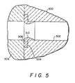
- Fig.5 illustrates yet another embodiment of the present invention in which the thermal barrier 506 not only extends over a portion of the end plate 504 of the mold 500, but also extends radially inwardly from interior surface 502 of the mold. As depicted, nozzle 508 abuts with the thermal barrier proximate to the flow of molten metal and a portion of end plate 504.
- the strength and integrity provided by the thermal barrier extending over the end plate of the mold enhances the ability of the portion of the thermal barrier extending into the cavity of the mold to withstand the stresses of the flowing molten metal and reduce the risk of chipping.
- the interior surface 510 of the thermal barrier is shown as being contoured and tapering into the interior surface 502 of the mold. Since the thermal barrier is integral with the interior surface 502, the deleterious effects of which could be caused by molten metal seeping betwen the components do not occur. Moreover, the contour at least partially replaces the void space characteristics of the break ring design of Figure 2, and can result in attentuated witness marks.
- the thermal barrier may constitute a wide variety of configurations provided that the thermal barrier extends over at least that portion of the end plate of the mold which is adjacent the interior surface of the mold.
- the end plate of the mold may be tapered or otherwise configured to provide more thermal barrier adjacent the interior surfce of the mold, such as for example by bevelling, routing, providing, for example, indentations.
- the transverse cross-section of the mould may be in virtually any shape limited by the ability to provide proper cooling to the flow of molten metal in the mould and the ability to apply (and machine, if necessary) the thermal barrier.
- near net shape horizontal castings can be produced with substantial reduction in capital and operating costs required to reform a conventional billet or bloom into the desired ultimate shape such as, for example, I-beam, plates or sheets.
- thermal barrier can be applied by a coating technique, moulds can be readily repaired. Further, since using thermal barrier materials also exhibit abrasion resistance, by coating a portion of the interior surface of the mould, such as in Figure 5, the useful life of the mould may be enhanced.
- a copper mould for the horizontal casting of steel is coated in accordance with the present invention on the end plate, or flange face, using an undercoat of Co-Ni-Cr-Al-Y and an overcoat of yttria stabilized zirconia.
- the throat of the copper mould is about 10.16 cm (about 4" long with a cross-section of 13.34 cm x 17.78 cm (5-1/4" x 7") with the corners having approximately a 0.32 cm (1/8") radius.
- the total flange face is about 27.78 cm x 23.34 cm (about 10-15/16" x 9-3/16") (with the throat centered in the flange face) and corners with about a 5.08 cm (2") radius.
- the periphery of the flange face has a 1.11 cm (7/16") wide lip about 0.95 cm (about 3/8") deep to contain a zirconia block used as a nozzle for pouring steel.
- the copper is first grit-blasted using 60 mesh alumina grit and then plasma sprayed with an undercoat of nominally 32Ni-21Cr-8Al-0.5Y-Bal Co., all in weight percent, to a thickness of 0.0076 to 0.0127 cm (0.003 to 0.005 inches). Over this metallic undercoat a zirconia coating consisting of ZrO2-7 wt.% Y2O3 is applied.
- the substrate is ground to a sharp corner prior to grit blasting and undercoating and then oversprayed with a total thickness of 0.0508-0.0635 cm (0.020-0.025 inches) of zirconia.
- the edge of the zirconia coating at the interior surface of the mould has a slight radius since some curvature is inherent in the coating process.
- the copper at the flange face is ground to a radius of about 0.127 cm (about 0.050 inches) before grit blasting and undercoating and subsequently coated at a 90° angle of impingement to a total coating thickness of about 1.308 cm (about 0.515 inches).
- a portion of this segment is then ground to a total zirconia coating thickness of 0.061 cm (0.024 inches), still leaving a small radius of curvature on the coated corner.
- the substrate is ground to a corner radius of about 0.127 cm (about 0.050 inches) prior to coating and subsequently coated at an angle of impingement slightly less than 90° to form a lip on the corner.
- the total zirconia coating thickness is about 0.325 cm (about 0.128 inches).
- a small portion of this segment is subsequently ground to a total coating thickness of 0.0577 cm (0.0227 inches) leaving a very sharp corner and a slightly negative angle of zirconia on the corner.
- An advantage of this configuration may be a somewhat better bond at the corner.
- the copper substrate is left with a sharp, round corner and about 0.307 cm (about 0.121 inches) of zirconia is applied. A portion of this segment is subsequently ground to a thickness of 0.145 cm (0.057 inches) leaving a very sharp corner on the zirconia. This remaining thickness of zirconia should be equivalent, thermally, to that which is currently used on conventional boron nitride break rings. The entire flange face could be ground to a uniform coating thickness.
- moulds having a thermal barrier may be employed for the continuous horizontal casting of metal such as, for example, steel.
Landscapes
- Engineering & Computer Science (AREA)
- Mechanical Engineering (AREA)
- Continuous Casting (AREA)
Applications Claiming Priority (2)
| Application Number | Priority Date | Filing Date | Title |
|---|---|---|---|
| US91909586A | 1986-10-15 | 1986-10-15 | |
| US919095 | 1986-10-15 |
Publications (2)
| Publication Number | Publication Date |
|---|---|
| EP0265174A2 true EP0265174A2 (fr) | 1988-04-27 |
| EP0265174A3 EP0265174A3 (fr) | 1989-06-14 |
Family
ID=25441500
Family Applications (1)
| Application Number | Title | Priority Date | Filing Date |
|---|---|---|---|
| EP87309112A Withdrawn EP0265174A3 (fr) | 1986-10-15 | 1987-10-15 | Lingotières pour la coulée continue |
Country Status (4)
| Country | Link |
|---|---|
| EP (1) | EP0265174A3 (fr) |
| JP (1) | JPS63157741A (fr) |
| KR (1) | KR880004873A (fr) |
| CA (1) | CA1296861C (fr) |
Cited By (5)
| Publication number | Priority date | Publication date | Assignee | Title |
|---|---|---|---|---|
| EP0355940A1 (fr) * | 1988-06-27 | 1990-02-28 | Chaparral Steel Co | Lingotière de coulée continue avec insert remplaçable. |
| EP0400683A1 (fr) * | 1989-06-02 | 1990-12-05 | Sugitani Kinzoku Kogyo Kabushiki Kaisha | Matériaux en poudre métallique pour le dépôt par pulvérisation, son procédé de fabrication et son utilisation |
| WO2008086862A1 (fr) | 2007-01-18 | 2008-07-24 | Sms Siemag Ag | Lingotière avec revêtement |
| CN100518996C (zh) * | 2007-09-04 | 2009-07-29 | 广州市锐优表面科技有限公司 | 一种在连续铸造结晶器表面制备强化涂层的方法 |
| EP2108471A2 (fr) * | 2008-04-03 | 2009-10-14 | KME Germany AG & Co. KG | Moule |
Families Citing this family (2)
| Publication number | Priority date | Publication date | Assignee | Title |
|---|---|---|---|---|
| JPH02180752A (ja) * | 1988-12-28 | 1990-07-13 | Kawasaki Refract Co Ltd | 連続鋳造用タンディッシュノズル |
| CN103447493B (zh) * | 2013-09-05 | 2015-06-17 | 东北大学 | 一种宽厚板连铸坯轻压下压下区间的控制方法 |
Family Cites Families (7)
| Publication number | Priority date | Publication date | Assignee | Title |
|---|---|---|---|---|
| BE754315A (fr) * | 1969-08-05 | 1971-01-18 | Hajduk Stan | Lingotiere de coulee continue refroidie par l'eau |
| DE2604478A1 (de) * | 1976-02-05 | 1977-08-11 | Peter Gloerfeld | Anordnung in einer horizontal arbeitenden stranggiessanlage |
| GB1570348A (en) * | 1977-04-28 | 1980-07-02 | British Steel Corp | Coated graphite dies |
| JPS53135826A (en) * | 1977-04-30 | 1978-11-27 | Sumitomo Metal Ind | Continuous casting method |
| GB8401976D0 (en) * | 1984-01-25 | 1984-02-29 | Imi Refiners Ltd | Casting apparatus |
| JPS6149752A (ja) * | 1984-08-17 | 1986-03-11 | Kobe Steel Ltd | コ−ルドシヤツト深さ低減用水平連鋳耐火物 |
| US4744406A (en) * | 1986-10-30 | 1988-05-17 | Chaparral Steel Company | Horizontal continuous casting apparatus with break ring formed integral with mold |
-
1987
- 1987-10-15 JP JP62258485A patent/JPS63157741A/ja active Pending
- 1987-10-15 KR KR870011587A patent/KR880004873A/ko not_active Ceased
- 1987-10-15 EP EP87309112A patent/EP0265174A3/fr not_active Withdrawn
- 1987-10-15 CA CA000551077A patent/CA1296861C/fr not_active Expired - Lifetime
Cited By (5)
| Publication number | Priority date | Publication date | Assignee | Title |
|---|---|---|---|---|
| EP0355940A1 (fr) * | 1988-06-27 | 1990-02-28 | Chaparral Steel Co | Lingotière de coulée continue avec insert remplaçable. |
| EP0400683A1 (fr) * | 1989-06-02 | 1990-12-05 | Sugitani Kinzoku Kogyo Kabushiki Kaisha | Matériaux en poudre métallique pour le dépôt par pulvérisation, son procédé de fabrication et son utilisation |
| WO2008086862A1 (fr) | 2007-01-18 | 2008-07-24 | Sms Siemag Ag | Lingotière avec revêtement |
| CN100518996C (zh) * | 2007-09-04 | 2009-07-29 | 广州市锐优表面科技有限公司 | 一种在连续铸造结晶器表面制备强化涂层的方法 |
| EP2108471A2 (fr) * | 2008-04-03 | 2009-10-14 | KME Germany AG & Co. KG | Moule |
Also Published As
| Publication number | Publication date |
|---|---|
| CA1296861C (fr) | 1992-03-10 |
| EP0265174A3 (fr) | 1989-06-14 |
| JPS63157741A (ja) | 1988-06-30 |
| KR880004873A (ko) | 1988-06-27 |
Similar Documents
| Publication | Publication Date | Title |
|---|---|---|
| US6255000B1 (en) | Single-cast, high-temperature, thin wall structures | |
| EP0635323B1 (fr) | Tuyère pour moulage continu | |
| US5012853A (en) | Process for making articles with smooth complex internal geometries | |
| JPH02502706A (ja) | 冶金用容器のための浸漬形注湯ノズル | |
| Singer et al. | Incremental solidification and forming | |
| US5474282A (en) | Titanium composite for molten metal | |
| EP0265174A2 (fr) | Lingotières pour la coulée continue | |
| EP0143822B1 (fr) | Produit refractaire composite | |
| CA1220606A (fr) | Enduit refractaire sur rives de moules pour prevenir l'affaissement longitudinal des pieces de coulee continue | |
| US20060051599A1 (en) | Coatings for articles used with molten metal | |
| EP0946778B1 (fr) | Revetement de composants de machine a moulage continu | |
| JP3265239B2 (ja) | 連続鋳造用浸漬ノズル | |
| US5435375A (en) | Titanium composite casting nozzle | |
| US4744406A (en) | Horizontal continuous casting apparatus with break ring formed integral with mold | |
| EP0355940A2 (fr) | Lingotière de coulée continue avec insert remplaçable | |
| JP2698186B2 (ja) | 鋳造用ノズル部材の製造方法 | |
| JPS5939223B2 (ja) | 溶融金属用複合ノズル | |
| US6176298B1 (en) | Continuous casting mould | |
| Singer et al. | Centrifugal spray forming of large-diameter tubes | |
| JPS62118948A (ja) | 高温ヘツドを有する連続鋳造鋳型 | |
| JPH0661596B2 (ja) | 金属の連続鋳造装置 | |
| JPH10277708A (ja) | 連続鋳造用鋳型 | |
| Annavarapu | Strip casting of plain carbon steel by spray deposition | |
| JPH08267183A (ja) | 連続鋳造用鋳型 | |
| JPH0275445A (ja) | 連続鋳造用モールドおよび連続鋳造方法 |
Legal Events
| Date | Code | Title | Description |
|---|---|---|---|
| PUAI | Public reference made under article 153(3) epc to a published international application that has entered the european phase |
Free format text: ORIGINAL CODE: 0009012 |
|
| AK | Designated contracting states |
Kind code of ref document: A2 Designated state(s): CH DE FR GB IT LI |
|
| PUAL | Search report despatched |
Free format text: ORIGINAL CODE: 0009013 |
|
| AK | Designated contracting states |
Kind code of ref document: A3 Designated state(s): CH DE FR GB IT LI |
|
| 17P | Request for examination filed |
Effective date: 19890829 |
|
| 17Q | First examination report despatched |
Effective date: 19900319 |
|
| STAA | Information on the status of an ep patent application or granted ep patent |
Free format text: STATUS: THE APPLICATION IS DEEMED TO BE WITHDRAWN |
|
| 18D | Application deemed to be withdrawn |
Effective date: 19930504 |
|
| RIN1 | Information on inventor provided before grant (corrected) |
Inventor name: TUCKER, ROBERT CLARK |