EP0265277A2 - Steuereinheit für Differential - Google Patents
Steuereinheit für Differential Download PDFInfo
- Publication number
- EP0265277A2 EP0265277A2 EP87309385A EP87309385A EP0265277A2 EP 0265277 A2 EP0265277 A2 EP 0265277A2 EP 87309385 A EP87309385 A EP 87309385A EP 87309385 A EP87309385 A EP 87309385A EP 0265277 A2 EP0265277 A2 EP 0265277A2
- Authority
- EP
- European Patent Office
- Prior art keywords
- differential
- torque
- controller
- limited slip
- control device
- Prior art date
- Legal status (The legal status is an assumption and is not a legal conclusion. Google has not performed a legal analysis and makes no representation as to the accuracy of the status listed.)
- Granted
Links
Images

Classifications
-
- B—PERFORMING OPERATIONS; TRANSPORTING
- B60—VEHICLES IN GENERAL
- B60K—ARRANGEMENT OR MOUNTING OF PROPULSION UNITS OR OF TRANSMISSIONS IN VEHICLES; ARRANGEMENT OR MOUNTING OF PLURAL DIVERSE PRIME-MOVERS IN VEHICLES; AUXILIARY DRIVES FOR VEHICLES; INSTRUMENTATION OR DASHBOARDS FOR VEHICLES; ARRANGEMENTS IN CONNECTION WITH COOLING, AIR INTAKE, GAS EXHAUST OR FUEL SUPPLY OF PROPULSION UNITS IN VEHICLES
- B60K23/00—Arrangement or mounting of control devices for vehicle transmissions, or parts thereof, not otherwise provided for
- B60K23/04—Arrangement or mounting of control devices for vehicle transmissions, or parts thereof, not otherwise provided for for differential gearing
Definitions
- This invention relates to a differential control device and, more particularly, to a device which controls the differential of a differential gear provided with a limited slip differential and installed on a vehicle.
- a differential gear capable of limiting the differential is provided with a limited slip differential including a plurality of friction disks and a hydraulic device for operating these friction disks or the like, in addition to a usual differential mechanism, in order to limit the differential produced in the differential mechanism by the contact of the friction disks.
- a limited slip differential including a plurality of friction disks and a hydraulic device for operating these friction disks or the like, in addition to a usual differential mechanism, in order to limit the differential produced in the differential mechanism by the contact of the friction disks.
- the differential is limited to improve travelling stability (for example, Japanese Patent Public Disclosure (KOKAI) 237242/85), or the limitation of the differential is released according to the size of turning angle to achieve both turning performance and travelling performance.
- tractive forces of tires need to be sufficiently ensured at the time of starting of a vehicle, acceleration with high speed, travelling on an uphill road and traction etc. any device for limiting the differential when the vehicle speed exceeds a predetermined value cannot obtain the necessary tractive forces.
- An object of the present invention is to provide a differential control device for controlling a limited slip differential to ensure the tractive forces at the time of starting, acceleration with high speed, travelling on an uphill road and traction and so on.
- a device for controlling the differential of a differential gear having a limited slip differential which comprises means for detecting drive torque, a controller for receiving a signal from said means to compare the size of the signal with a predetermined value and means controlled by a signal from said controller to operate said limited slip differential so as to limit the differential when the drive torque exceeds the predetermined value.
- a device for controlling the differential of a differential gear having a limited slip differential which comprises means for detecting a drive torque condition, a controller for obtaining torque based on a signal from said means and comparing the obtained torque with a predetermined value and means controlled by a signal from said controller to operate said limited slip differential so as to limit the differential when the obtained torque exceeds the predetermined value.
- the controller compares the torque with a predetermined value and, when the torque exceeds the predetermined value, operates the operating means to limit the differential.
- the differential between left and right tires is limited so that large torque may be given to the tires.
- the controller for example, handles a steering angle in preference to the torque and releases the limitation of the differential when the steering angle exceeds a predetermined value.
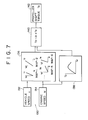
- a differential control device 10 limits the differential of a differential gear 14 having a limited slip differential 12 and comprises means 16 for detecting drive torque, a controller 18 and operating means 20.
- the differential gear 14 shown in Fig. 3 is constituted from a differential case 22, a plurality of pinions 24 and a pair of side gears 26 (each one of them is shown in the drawing) respectively disposed in the differential case 22 and shafts 28 connected to respective side gears 26.
- a drive pinion (not shown) meshes with a ring gear 29 to transmit drive force.
- the limited slip differential 12 limits the differential of the differential gear 14 and is provided with a plurality of first friction disks 30 engaging one side gear 26 and a plurality of second friction disks 32 engaging the differential case 22.
- a first differential carrier 34 is fixedly disposed to surround and support rotatably the differential case 22.
- a second differential carrier 36 is fixed to the first differential carrier 34.
- a cylindrical spacer 38 is mounted unrotatably on the shaft 28 through splines.
- the first friction disks 30 are supported on the spacer 38 through splines unrotatably but axially movably of the shaft 28.
- a transmitting member 40 unrotatably connected with the differential case 22 through splines is disposed to surround the shaft 28.
- the transmitting member 40 is provided with a portion having a diameter which is expanded at a position beyond the first differential carrier 34.
- the second friction disks 32 are supported on the expanded diameter portion through splines unrotatably but axially movably.
- the first and second friction disks 30,32 are disposed alternatively.
- the second differential carrier 36 surrounds the expanded diameter portion of the transmitting member 40.
- the differential carrier 36 is provided with a piston chamber 42 in which a first piston 44 is disposed slidably but unrotatably.
- a second piston 46 is disposed spacedly from the first piston 44 and supported on the spacer 38 through splines unrotatably but axially movably.
- a thrust bearing 48 is disposed between the first and second pistons 44,46.
- the means 16 for detecting torque is a wheel torque meter or other torque detectors to detect the drive torque of a drive shaft or propeller shaft at the neighborhood of a driving wheel.
- the controller 18 is a CPU or computer for receiving signals from the torque detecting means 16 to judge the size of torque, determine whether or not the differential should be limited or the limitation of the differential is released and then control as will be later described. In an embodiment shown in Figs. 1 and 2, signals from a steering angle sensor 60 and a vehicle speed sensor 62 are sent to the input of the controller 18.
- the operating means 20 shown in the embodiment is provided with a liquid pump 64, an unloading relief valve 66, an accumulator 68, a current control pressure-reducing valve 70 and a check valve 72.
- a pipe 74 is connected to the pump 64 and the second differential carrier 36 of the limited slip differential 12 to communicate to the piston chamber 42.
- the unloading relief valve 66 is incorporated in the pipe 74 and the current control pressure-reducing valve 70 is incorporated in a portion of the pipe leading from the unloading relief valve 66 to the limited slip differential 12.
- the accumulator 68 is connected between the unloading relief valve 66 and the current control pressure-reducing valve 70.
- the check valve 72 is incorporated between the unloading relief valve 66 and the accumulator 68. The check valve 72 allows liquid or pressure to be respectively sent or transmitted only from the unloading relief valve 66 to the accumulator 68.
- the current control pressure-reducing valve 70 has a pilot section provided with a DC solenoid. Output pressure therefrom is controlled continuously and non-steplessly by controlling input current to the solenoid.
- the controlled pressure in this case is substantially proportional to the input current. Then, proper pressure may be obtained by controlling input current given to the current control pressure-reducing valve 70 by the controller 18.
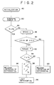
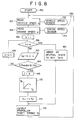
- the controller 18 judges as shown in Fig. 2, for example, to control the operating means 20.
- a steering angle S is detected (82) by the steering angle sensor 60 and compared (84) with a set value So.
- the limitation of the differential of the differential gear 14 is released (86). Namely, any differential will be produced and turning will be done without any trouble.
- the current control pressure-reducing valve 70 supplies pressure in proportion to current to the limited slip differential 12.
- the differential may be limited in proportion to the size of the torque T.
- the relationship between the torque T and the pressure P to be given to the liquid chamber 42 and the relationship between the pressure P and the current i are stored as respective maps in the controller 18 to limit the differential by utilizing these relationships.
- the controller 18 obtains (98) the pressure P according to the torque T and the current i according to the pressure P from the maps.
- the current i is then supplied to the current control pressure-reducing valve 70.
- the pressure P is supplied to the limited slip differential 12, so that the first piston 44 presses the second piston 46 with the force in proportion to the pressure. Therefore, the first and second friction disks 30,32 contact each other to generate the frictional force in proportion to the pressure and limit the differential of the differential gear 14.
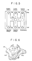
- means 110 for detecting the drive torque condition includes a sensor 112 for detecting a shift position of a transmission and a sensor 114 for detecting an engine speed.
- the shift position detecting sensor 112 in a manual operation is constituted from a detecting plate 118 having switches 119a,119b ... 119f disposed respectively at the shift positions occupied by a shift lever 116 in the first speed to fifth speed and reverse drive.
- Each switch may be a limit switch, a proximity switch or other switches.
- the shift position sensor 112 in an automatic operation is constituted from solenoid valves and a neutral start switch 120 shown in Fig. 6. That is, a plurality of solenoid valves S1, S2, S3 are used to shift gears of a transmission, and the relationship shown on the following table, for example, is established between their operational conditions and the shift positions of the gears;
- the neutral start switch 120 includes a printed circuit substrate 121a and a change-over lever 121b. Accoridng to the position of the change-over lever 121b are detected parking P, reverse R, neutral N, forward drive D and so on. Then, the shift position may be known by the combination of the signals of solenoid valves and neutral start switch 120.
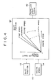
- the controller 18 is provided with maps 122 each stored the correlation between the engine speed and torque of a propeller shaft (the correlations are shown only in one map for convenience in Fig. 4) in every shift position.
- maps 122 each stored the correlation between the engine speed and torque of a propeller shaft (the correlations are shown only in one map for convenience in Fig. 4) in every shift position.
- means 130 for detecting a drive torque condition includes a vehicle speed sensor 132 and an engine speed sensor 134. On the basis of signals from these sensors, the controller 18 obtains the torque as follows;
- the controller 18 When the vehicle speed U and engine speed ⁇ are sent to the input of the controller 18, the controller 18 obtains the reduction ratio i k corresponding to both signals from the maps 136 and obtains the engine torque T2 from the map 138 on the basis of the engine speed. Thereafter, the product of reduction ratio i k and engine torque T2 is calculated (140) to obtain the torque T3 of the propeller shaft (142).
- the operating means 20 is operated to give the frictional force corresponding to the torque T3 to the limited slip differential 12.
- the torque T3 is set (160) to zero.
- the reduction ratio I is set (166) to i k .
- k is (168) set to (k+1) and k thus set is compared (158) with 6.
- the controller 18 is previously stored (170) he correlation between the engine speed ⁇ and the engine torque T2 to obtain the engine torque T2 from the detected engine speed ⁇ .
- the torque T3 of the propeller shaft which is to be given to the limited slip differential 12 by the operating means 20 is calculated (172) from the reduction ratio I and engine torque T2 and outputted (174).
Landscapes
- Engineering & Computer Science (AREA)
- Chemical & Material Sciences (AREA)
- Combustion & Propulsion (AREA)
- Transportation (AREA)
- Mechanical Engineering (AREA)
- Arrangement And Mounting Of Devices That Control Transmission Of Motive Force (AREA)
Applications Claiming Priority (2)
| Application Number | Priority Date | Filing Date | Title |
|---|---|---|---|
| JP252060/86 | 1986-10-24 | ||
| JP61252060A JPH0788141B2 (ja) | 1986-10-24 | 1986-10-24 | 差動制御装置 |
Publications (3)
| Publication Number | Publication Date |
|---|---|
| EP0265277A2 true EP0265277A2 (de) | 1988-04-27 |
| EP0265277A3 EP0265277A3 (en) | 1989-10-18 |
| EP0265277B1 EP0265277B1 (de) | 1991-12-27 |
Family
ID=17232000
Family Applications (1)
| Application Number | Title | Priority Date | Filing Date |
|---|---|---|---|
| EP87309385A Expired - Lifetime EP0265277B1 (de) | 1986-10-24 | 1987-10-23 | Steuereinheit für Differential |
Country Status (4)
| Country | Link |
|---|---|
| US (1) | US4872373A (de) |
| EP (1) | EP0265277B1 (de) |
| JP (1) | JPH0788141B2 (de) |
| DE (1) | DE3775516D1 (de) |
Cited By (6)
| Publication number | Priority date | Publication date | Assignee | Title |
|---|---|---|---|---|
| EP0415654A3 (en) * | 1989-08-31 | 1992-04-08 | Fuji Jukogyo Kabushiki Kaisha | System for controlling distribution of torque to left and right wheels of a motor vehicle |
| EP0467351A3 (en) * | 1990-07-18 | 1993-03-31 | Hurth Axle S.P.A. | Device and process for the automatic control of the locking of differential gearings |
| EP0390362B1 (de) * | 1989-03-31 | 1993-05-26 | Fuji Jukogyo Kabushiki Kaisha | Antriebsübertragungssystem für Kraftfahrzeuge |
| AT398056B (de) * | 1989-07-28 | 1994-09-26 | Steyr Daimler Puch Ag | Ausgleichgetriebesperre für kraftfahrzeuge |
| AT398948B (de) * | 1989-10-25 | 1995-02-27 | Steyr Daimler Puch Ag | Verteilergetriebe für ein kraftfahrzeug |
| WO2005018975A1 (de) * | 2003-08-02 | 2005-03-03 | Zf Friedrichshafen Ag | Verfahren zur ansteuerung der quersperren für ein nutz- bzw. einsatzfahrzeug |
Families Citing this family (8)
| Publication number | Priority date | Publication date | Assignee | Title |
|---|---|---|---|---|
| ATA100988A (de) * | 1988-04-20 | 1994-09-15 | Steyr Daimler Puch Ag | Differentialgetriebe |
| DE3837862C2 (de) * | 1988-11-08 | 1993-09-30 | Gkn Automotive Ag | Vorrichtung zur Steuerung von Sperrdifferentialen |
| JP2894403B2 (ja) * | 1991-11-07 | 1999-05-24 | 三菱自動車工業株式会社 | 差動制限式左右輪駆動力配分制御装置 |
| JP3207328B2 (ja) * | 1994-12-16 | 2001-09-10 | 三菱電機株式会社 | 車両制御用軸トルク検出装置 |
| DE19913824B4 (de) * | 1999-03-26 | 2010-04-01 | Robert Bosch Gmbh | Verfahren und Vorrichtung zur Steuerung einer Antriebseinheit |
| JP5256067B2 (ja) * | 2009-02-03 | 2013-08-07 | 株式会社Kcm | ホイールローダの差動制限装置 |
| WO2022215447A1 (ja) | 2021-04-05 | 2022-10-13 | 日立建機株式会社 | 車両用アクスル装置 |
| US12528198B2 (en) | 2021-07-09 | 2026-01-20 | Taiwan Semiconductor Manufacturing Company, Ltd. | Robot magazine and tray load and unload system |
Family Cites Families (14)
| Publication number | Priority date | Publication date | Assignee | Title |
|---|---|---|---|---|
| JPS5719297Y2 (de) * | 1977-07-25 | 1982-04-22 | ||
| JPS58160818A (ja) * | 1982-03-18 | 1983-09-24 | Toyota Motor Corp | 変速操作指示装置 |
| JPS58177642U (ja) * | 1982-05-21 | 1983-11-28 | 日産自動車株式会社 | リミテツド・スリツプ・デイフアレンシヤル装置 |
| US4523494A (en) * | 1983-06-13 | 1985-06-18 | Deere & Company | Steering pressure responsive differential lock control system |
| US4570509A (en) * | 1983-06-13 | 1986-02-18 | Deere & Company | Differential lock control system responsive to steering and/or braking action to unlock differential |
| GB8332268D0 (en) * | 1983-12-02 | 1984-01-11 | Shell Int Research | Herbicides |
| JPS60175857A (ja) * | 1984-02-20 | 1985-09-10 | Diesel Kiki Co Ltd | 車輛用自動変速制御装置 |
| DE3425691A1 (de) * | 1984-07-12 | 1986-01-23 | Klöckner-Humboldt-Deutz AG, 5000 Köln | Vorrichtung zum form- oder kraftschluessigen einschalten einer differentialsperre |
| JPS6144027A (ja) * | 1984-08-08 | 1986-03-03 | Nissan Motor Co Ltd | 前後輪駆動車の前後輪差動制御装置 |
| US4679463A (en) * | 1984-08-31 | 1987-07-14 | Nissan Motor Co., Ltd. | Limited slip differential |
| JPS61132420A (ja) * | 1984-11-30 | 1986-06-19 | Hino Motors Ltd | 自動車の走行安定装置 |
| JPS6294421A (ja) * | 1985-10-18 | 1987-04-30 | Fuji Heavy Ind Ltd | 車両の後輪駆動装置 |
| JPS62110529A (ja) * | 1985-11-08 | 1987-05-21 | Nissan Motor Co Ltd | 車両用差動制限制御装置 |
| US5299274A (en) * | 1992-06-25 | 1994-03-29 | Hughes Aircraft Company | Optical fiber laser fusion splicer |
-
1986
- 1986-10-24 JP JP61252060A patent/JPH0788141B2/ja not_active Expired - Lifetime
-
1987
- 1987-10-22 US US07/111,264 patent/US4872373A/en not_active Expired - Lifetime
- 1987-10-23 EP EP87309385A patent/EP0265277B1/de not_active Expired - Lifetime
- 1987-10-23 DE DE8787309385T patent/DE3775516D1/de not_active Expired - Lifetime
Cited By (6)
| Publication number | Priority date | Publication date | Assignee | Title |
|---|---|---|---|---|
| EP0390362B1 (de) * | 1989-03-31 | 1993-05-26 | Fuji Jukogyo Kabushiki Kaisha | Antriebsübertragungssystem für Kraftfahrzeuge |
| AT398056B (de) * | 1989-07-28 | 1994-09-26 | Steyr Daimler Puch Ag | Ausgleichgetriebesperre für kraftfahrzeuge |
| EP0415654A3 (en) * | 1989-08-31 | 1992-04-08 | Fuji Jukogyo Kabushiki Kaisha | System for controlling distribution of torque to left and right wheels of a motor vehicle |
| AT398948B (de) * | 1989-10-25 | 1995-02-27 | Steyr Daimler Puch Ag | Verteilergetriebe für ein kraftfahrzeug |
| EP0467351A3 (en) * | 1990-07-18 | 1993-03-31 | Hurth Axle S.P.A. | Device and process for the automatic control of the locking of differential gearings |
| WO2005018975A1 (de) * | 2003-08-02 | 2005-03-03 | Zf Friedrichshafen Ag | Verfahren zur ansteuerung der quersperren für ein nutz- bzw. einsatzfahrzeug |
Also Published As
| Publication number | Publication date |
|---|---|
| US4872373A (en) | 1989-10-10 |
| JPS63106140A (ja) | 1988-05-11 |
| EP0265277B1 (de) | 1991-12-27 |
| EP0265277A3 (en) | 1989-10-18 |
| JPH0788141B2 (ja) | 1995-09-27 |
| DE3775516D1 (de) | 1992-02-06 |
Similar Documents
| Publication | Publication Date | Title |
|---|---|---|
| EP0265277A2 (de) | Steuereinheit für Differential | |
| US6543311B1 (en) | Driving system for industrial trucks | |
| US5218541A (en) | Automatic transmission control system responsive to road surface conditions | |
| KR860003127A (ko) | 차량용 감속 제어시스템 | |
| JPH0462895B2 (de) | ||
| JPH09202159A (ja) | 発進クラッチを備えた車両におけるブレーキ力制御装置 | |
| JPH10504877A (ja) | 走行駆動装置 | |
| JPH0462896B2 (de) | ||
| US4841808A (en) | Differential control device | |
| EP0256746B1 (de) | Steuerungseinrichtung für die Ausgleichsfunktion eines Differentialgetriebes | |
| US5489007A (en) | Dynamic braking on an all wheel drive machine | |
| US4867262A (en) | Four wheel drive system for vehicle | |
| JPH10306874A (ja) | 油圧式車両 | |
| JP2674017B2 (ja) | 差動制御装置 | |
| JP3133523B2 (ja) | 4輪走行装置の制御装置 | |
| JPH0411864Y2 (de) | ||
| JPH07139608A (ja) | 無限減速比変速機の変速制御装置 | |
| JPH0524575Y2 (de) | ||
| JPH08282324A (ja) | 2輪駆動車の減速エネルギー利用方法及びその利用装置 | |
| JP2674023B2 (ja) | 差動制御装置 | |
| JPH05169996A (ja) | 4輪駆動車 | |
| JPH05246259A (ja) | 4輪駆動車 | |
| JPH0434269Y2 (de) | ||
| JP2876232B2 (ja) | 無段変速機の制御装置 | |
| JP3113890B2 (ja) | 車輛の駆動制御装置 |
Legal Events
| Date | Code | Title | Description |
|---|---|---|---|
| PUAI | Public reference made under article 153(3) epc to a published international application that has entered the european phase |
Free format text: ORIGINAL CODE: 0009012 |
|
| AK | Designated contracting states |
Kind code of ref document: A2 Designated state(s): DE GB |
|
| PUAL | Search report despatched |
Free format text: ORIGINAL CODE: 0009013 |
|
| AK | Designated contracting states |
Kind code of ref document: A3 Designated state(s): DE GB |
|
| 17P | Request for examination filed |
Effective date: 19891125 |
|
| 17Q | First examination report despatched |
Effective date: 19901016 |
|
| GRAA | (expected) grant |
Free format text: ORIGINAL CODE: 0009210 |
|
| AK | Designated contracting states |
Kind code of ref document: B1 Designated state(s): DE GB |
|
| REF | Corresponds to: |
Ref document number: 3775516 Country of ref document: DE Date of ref document: 19920206 |
|
| PLBE | No opposition filed within time limit |
Free format text: ORIGINAL CODE: 0009261 |
|
| STAA | Information on the status of an ep patent application or granted ep patent |
Free format text: STATUS: NO OPPOSITION FILED WITHIN TIME LIMIT |
|
| 26N | No opposition filed | ||
| REG | Reference to a national code |
Ref country code: GB Ref legal event code: 746 Effective date: 19960122 |
|
| REG | Reference to a national code |
Ref country code: GB Ref legal event code: IF02 |
|
| PGFP | Annual fee paid to national office [announced via postgrant information from national office to epo] |
Ref country code: GB Payment date: 20061018 Year of fee payment: 20 |
|
| PGFP | Annual fee paid to national office [announced via postgrant information from national office to epo] |
Ref country code: DE Payment date: 20061019 Year of fee payment: 20 |
|
| REG | Reference to a national code |
Ref country code: GB Ref legal event code: PE20 |
|
| PG25 | Lapsed in a contracting state [announced via postgrant information from national office to epo] |
Ref country code: GB Free format text: LAPSE BECAUSE OF EXPIRATION OF PROTECTION Effective date: 20071022 |