EP0265539B1 - Bürstenloser Einphasenmotor - Google Patents
Bürstenloser Einphasenmotor Download PDFInfo
- Publication number
- EP0265539B1 EP0265539B1 EP86114960A EP86114960A EP0265539B1 EP 0265539 B1 EP0265539 B1 EP 0265539B1 EP 86114960 A EP86114960 A EP 86114960A EP 86114960 A EP86114960 A EP 86114960A EP 0265539 B1 EP0265539 B1 EP 0265539B1
- Authority
- EP
- European Patent Office
- Prior art keywords
- phase
- armature coil
- wound
- stator
- armature
- Prior art date
- Legal status (The legal status is an assumption and is not a legal conclusion. Google has not performed a legal analysis and makes no representation as to the accuracy of the status listed.)
- Expired - Lifetime
Links
Images




Classifications
-
- H—ELECTRICITY
- H02—GENERATION; CONVERSION OR DISTRIBUTION OF ELECTRIC POWER
- H02P—CONTROL OR REGULATION OF ELECTRIC MOTORS, ELECTRIC GENERATORS OR DYNAMO-ELECTRIC CONVERTERS; CONTROLLING TRANSFORMERS, REACTORS OR CHOKE COILS
- H02P6/00—Arrangements for controlling synchronous motors or other dynamo-electric motors using electronic commutation dependent on the rotor position; Electronic commutators therefor
- H02P6/10—Arrangements for controlling torque ripple, e.g. providing reduced torque ripple
-
- H—ELECTRICITY
- H02—GENERATION; CONVERSION OR DISTRIBUTION OF ELECTRIC POWER
- H02K—DYNAMO-ELECTRIC MACHINES
- H02K29/00—Motors or generators having non-mechanical commutating devices, e.g. discharge tubes or semiconductor devices
- H02K29/06—Motors or generators having non-mechanical commutating devices, e.g. discharge tubes or semiconductor devices with position sensing devices
- H02K29/08—Motors or generators having non-mechanical commutating devices, e.g. discharge tubes or semiconductor devices with position sensing devices using magnetic effect devices, e.g. Hall-plates, magneto-resistors
-
- H—ELECTRICITY
- H02—GENERATION; CONVERSION OR DISTRIBUTION OF ELECTRIC POWER
- H02P—CONTROL OR REGULATION OF ELECTRIC MOTORS, ELECTRIC GENERATORS OR DYNAMO-ELECTRIC CONVERTERS; CONTROLLING TRANSFORMERS, REACTORS OR CHOKE COILS
- H02P6/00—Arrangements for controlling synchronous motors or other dynamo-electric motors using electronic commutation dependent on the rotor position; Electronic commutators therefor
- H02P6/26—Arrangements for controlling single phase motors
Definitions
- This invention relates to a single-phase brushless motor which is well adapted for a spindle motor for a floppy disk drive, a motor for audio and video appliances, and a DC brushless axial-flow fan motor.
- a brushless DC-motor which is provided with three magnetic-field-dependent resistors mounted on a three-armed pole metal sheet. Magnetic connection metal sheets are mounted on these resistors. Between the magnetic connection metal sheet and the pole metal sheet a permanent magnet is arranged to bias the magnetic-field-dependent resistors for influencing the characteristic of the motor.
- a brushless motor is used in a variety of appliances owing to its advantages that it makes little noises and has a long life because it has neither brush nor commutator in addition to its characteristics as a DC motor.
- an electronic circuit is used to switch energization of armature coils of the motor and includes a driving circuit which necessarily includes a number of position detecting elements (normally, magnetic sensors such as Hall effect elements and Hall ICs ore used) corresponding to the number of applicable phases of the motor. Accordingly, it is a drawback that as the number of phases increases, the production cost increases accordingly due to such position detecting elements.
- inexpensive appliances such as axialflow fans commonly employ a single-phase brushless motor which includes a driving circuit designed for a single-phase and hence can be produced at a low cost.
- Such a single-phase brushless motor has a drawback that it cannot start itself if it stops at a dead point.
- a conventional single-phase brushless motor is normally provided with special means such as a cogging torque (reluctance torque) generating member such as an iron bar located in an air gap or a special stator armature providing a slanted or sloped air gap for generating a cogging torque to assure self-starting of a magnet rotor of the motor.
- a cogging torque suscepttance torque
- a stator armature providing a slanted or sloped air gap for generating a cogging torque to assure self-starting of a magnet rotor of the motor.
- Such conventional single-phase brushless motors utilizing a cogging torque as described above have a drawback that smooth rotation cannot be attained due to generation of a high cogging torque.
- the brushless motor employing an iron bar has a relatively large number of parts while the brushless motor employing a special stator armature cannot provide a high turning torque and is low in efficiency.
- Single phase brushless motors are also known wherein a non-magnetized zone (or a substantially non-magnetized zone) is formed on a driving field magnet.
- Brushless motors of this type have a drawback that it is difficult and troublesome to form such a non-magnetized zone, which is not suitable for mass production of brushless motors of the type.
- a single-phase brushless motor comprising a field magnet as a rotor having 2P (P is an integer equal to or greater than 1) alternate north and south magnetic pole zones, each of either the north or the south magnetic pole zones of said field magnet having an angular width equal to an electrical angle of 120 or about 120 degrees while each of the other magnetic pole zones has an angular width equal to an electrical angle of 240 or about 240 degrees, a stator armature core having a plurality of stator poles formed thereon in an opposing relationship to said field magnet with an air gap left therebetween, a plurality of armature coils wound on said stator poles of said stator armature core and including first n (n is an integer equal to or greater than 1) armature coil or coils for the phase A wound on one or ones of said stator poles formed at a position or positions of an electrical angle of m ⁇ (360 ⁇ a) or about m ⁇ (360 ⁇ a) degrees (m is an
- the single-phase brushless motor according to the present invention can have a generally uniform air gap because it does not make use of a cogging torque for allowing self-starting of the motor as in conventional single-phase brushless motors. Accordingly, single-phase brushless motors can be obtained which have a generally smooth torque characteristic over a wide output range and hence can rotate smoothly without torque irregularities caused by a cogging torque for allowing self-starting of such motors.
- the single-phase brushless motor according to the invention does not involve a sloped or slanted air gap, a high torque can be attained and the stator armature core can be made simple and formed easily. Accordingly, single-phase brushless motors particularly of the cored type can be very readily produced in a mass at a low cost.
- the single-phase brushless motor according to the invention is further advantageous in that there is no necessity of forming a non-magnetized portion on the field magnet which deteriorates the mass-productivity of single-phase brushless motors.
- a cup-shaped, single-phase brushless motor 1 shown in FIG. 1 includes a 2-pole driving magnet rotor (field magnet) 2 and a stator armature core 3 having 3 radially extending T-shaped stator poles 5-1, 5-2, 5-3.
- the 2-pole driving magnet rotor 2 has an N (north) magnetic pole or pole zone having an angular width equal to an electrical angle of 120 or about 120 degrees (equal in mechanical angle) and an S (south) magnetic pole or pole zone having an angular width equal to an electrical angle of 240 or about 240 degrees (equal in mechanical angle).
- the N and S magnetic pole zones of the driving magnet rotor 2 are magnetized in radial directions, and the ratio in angular width between the N and S pole zones is 1:2 or about 1:2.
- the armature core 3 is located in an opposing relationship to the driving magnet rotor 2 with a radial air gap 4 left therebetween.
- the 3 T-shaped stator poles 5-1 5-2, 5-3 of the armature core 3 are circumferentially spaced by an angular distance equal to an electrical angle of 60 or about 60 degrees (120 degrees in mechanical angle) from each other.
- a first armature coil 6-1 for the phase A is wound on the stator pole 5-1.
- a second armature coil 6-2 for the phase A is wound on the stator pole 41-2 in a winding direction reverse to that of the first armature coil 6-1 for the phase A.
- the first and second armature coils 6-1, 6-2 constitute an armature coil 6A for the phase A.
- a third armature coil 6-3 for the phase A ⁇ is also wound on the stator pole 5-2 in a winding direction reverse to the first armature coil 6-1 for the phase A.
- a fourth armature coil 6-4 for the phase A ⁇ is wound on the stator pole 5-3 in a same winding direction with the first armature coil 6-1 for the phase A.
- the third and fourth armature coils 6-3 and 6-4 constitute an armature coil 6A ⁇ for the phase A ⁇ .
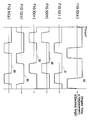
- FIG. 2(a) A developed view of the single-phase brushless motor 1 having such a construction as described above is shown in FIG. 2(a), and FIG. 2(b) shows a developed view of the armature coils 6A, 6A ⁇ for the phases A, A ⁇ .
- FIGS. 2(c) to 2(g) are diagrams showing torque curves generated by the armature coils 6A, 6A ⁇ of the single-phase brushless motor 1, and in those figures, the abscissa represents an angular displacement ( ⁇ ) of the rotor of the motor 1 and the ordinate represents a torque (T).
- FIG. 2(h) is a diagrammatic representation indicating ranges of the angular rotor displacement in electrical angle ( ⁇ ) associated with FIGS. 2(c) to 2(g).
- a torque curve 8 as shown in FIG. 2(d) is obtained by the second armature coil 6-2 of the armature coil 6A.
- a torque curve 9 as shown in FIG. 2(e) is obtained by the third armature coil 6-3 of the armature coil 6A ⁇ .
- a torque curve 10 as shown in FIG. 2(f) is obtained by the fourth armature coil 6-4 for the phase A ⁇ of the armature coil 6A ⁇ .
- a uniform torque of a substantially fixed value in a forward direction is obtained over a range of an electrical angle of 240 or about 240 degrees during one full rotation (360 degrees in electrical angle) of the rotor of the motor 1, and a torque in the reverse direction is obtained over a range of the remaining electrical angle of 120 or about 120 degrees.
- the latter torque in the reverse direction does not contribute to rotation of the motor 1.
- Such a composite torque curve 11 can be produced easily from a composite back EMF (electromotive force) waveform which is produced by combining a composite waveform between waveforms of back EMFs (electromotive forces) appearing in the first and second armature coils 6-1 and 6-2 of the armature coil 6A for the phase A with a composite waveform between waveforms of back EMFs produced in the third and fourth armature coils 6-3 and 6-4 of the armature coil 6A ⁇ for the phase A ⁇ .
- the composite torque curve 11 is actually obtained by inverting the composite back EMF waveform.
- a torque for rotating the motor 1 will be obtained if the armature coils 6A, 6A ⁇ for the phases A, A ⁇ are energized over a range of an electrical angle of 180 or about 180 degrees within the range of the electrical angle of 240 or about 240 degrees of the composite bac k EMF waveform.
- the positive torque that is, the torque in the forward direction
- the composite torque curve 11 is made use of as a torque for the motor.
- the positive torque within the range of the electrical angle of 240 or about 240 degrees of the composite torque curve 11 of FIG. 2(h) can be made use of as a torque of the motor, but the negative torque, that is, the torque in the reverse direction, within the range of the remaining electrical angle of 120 or about 120 degrees cannot be made use of as a torque of the motor.
- additional armature coils for the phases B, B ⁇ similar to the armature coils for the phases A, A ⁇ may be provided at locations spaced by an angular distance equal to an electrical angle of 180 or about 180 degrees from the corresponding armature coils A, A ⁇ for the phases A, A ⁇ , and the armature coils A, A ⁇ for the phases A, A ⁇ and the armature coils B, B ⁇ for the phases B, B ⁇ may be energized in an alternate relationship at intervals of an electrical angle of 180 or about 180 degrees.
- the single-phase brushless motor thus obtained can start itself without provision of a special self-starting enabling means (i.e., a cogging torque generating means; naturally, however, additional employment of such special means is allowed) and can generate a torque generally with reduced torque ripples over a complete rotation (over an electrical angle of 360 degrees) of the motor.
- a special self-starting enabling means i.e., a cogging torque generating means; naturally, however, additional employment of such special means is allowed
- the brushless motor is generally denoted at 12 and includes a generally cup-shaped motor body 13 formed from a stack of soft steel plates and constituting a stator.
- a rotary shaft 14 is supported for rotation at a substantially central portion of the motor body 13 by means of a pair of bearings 15.
- a cup-shaped rotor yoke 16 is secured to the rotary shaft 14 within a range of the motor body 13.
- a cylindrical 2-pole magnet rotor 2 (same reference numeral 2 is used here because a like magnet rotor to the magnet rotor 2 of the motor 1 of FIG. 1 is employed) is secured to an inner circumferential face of the rotor yoke 16 while a stator armature core 18 is securely supported on a support stator 44 secured to the motor body 13 and is opposed to the magnet rotor 2 with a radial air gap 4 left therebetween.
- the stator armature core 18 has six T-shaped stator poles 17-1 to 17-6 extending radially from an annular central interconnecting portion 18a and circumferentially spaced by an equal electrical angle of 60 degrees or about 60 degrees (same in mechanical angle) from each other as seen from FIG. 4.
- An axially magnetized 2-pole position detecting magnet rotor 19 as shown in FIG. 5 is formed at, for example, by application to, a lower end of the magnet rotor 2.
- the position detecting magnet rotor 19 has an N magnetic pole zone 19N and an S magnetic pole zone 19S each having an angular width equal to an electrical angle of 180 or about 180 degrees (same in mechanical angle).
- the position detecting magnet rotor 19 is shown applied directly to the lower end face of the driving magnet rotor 2, it may otherwise be applied thereto with a yoke interposed therebetween or alternatively it may be formed by axially magnetizing a lower end portion of the driving magnet rotor 2. It is to be noted that this also applies to any other embodiment of the invention described hereinbelow.
- a printed circuit board 23 on which a printed wiring pattern no t shown is formed is securely supported in a horizontal position by an engaging shoulder 21 formed on the support stator 20 and another engaging shoulder 22 formed on the motor body 13.
- an electric part accommodating spacing 24 is formed between the printed circuit board 23 and the bottom of the motor body 13.
- Electric parts 25 constituting an electric circuit are located on a lower face of the printed circuit board 23 within the electric part accommodating spacing 24. Meanwhile, a position detecting element 26 constituted from a magnetic sensor such as a Hall effect element or a Hall IC is located on an upper face of the printed circuit board 23 opposing to the position detecting magnet rotor 19 in order to detect a magnetic pole of the position detecting magnet rotor 19.
- a position detecting element 26 constituted from a magnetic sensor such as a Hall effect element or a Hall IC is located on an upper face of the printed circuit board 23 opposing to the position detecting magnet rotor 19 in order to detect a magnetic pole of the position detecting magnet rotor 19.
- a second armature coil 27-2 for the phase A is wound on the stator pole 17-3 in a winding direction reverse to that of the first armature coil 27-1 for the phase A.
- the armature coils 27-1 and 27-2 constitute an armature coil 27A (refer to FIG. 6) for the phase A.
- a third armature coil 27-3 for the phase A ⁇ is also wound on the stator pole 17-3 in a winding direction reverse to that of the first armature coil 27-1 for the phase A.
- a fourth armature coil 27-4 for the phase A ⁇ is wound on the stator pole 17-5 in the same winding direction with the first armature coil 27-1 for the phase A.
- the armature coils 27-3 and 27-4 constitute an armature coil 27A ⁇ (refer to FIG. 6) for the phase A ⁇ .
- the second armature coil 27-2 for the phase A and the third armature coil 27-3 for the phase A ⁇ are wound commonly on the stator pole 17-3 both in the reverse winding direction, they are described, for convenience of description, as if they were two separate armature coils, but they may be regarded actually as a single armature coil having a twice number of wound turns of a conductor.
- a fifth armature coil 27-5 for the phase B is wound on the stator pole 17-4 in the same winding direction with the first armature coil 27-1 for the phase A.
- a sixth armature coil 27-6 for the phase B is wound on the stator pole 17-6 in the reverse winding direction to that of the first armature coil 27-1 for the phase A.
- a seventh armature coil 27-7 for the phase B ⁇ is wound on the stator pole 17-6 in the reverse winding directionto that of the first armature coil 27-1 for the phase A.
- the fifth and sixth armature coils 27-5 and 27-6 for the phase B constitute an armature coil 27B for the phase B (refer to FIG. 6).
- the seventh and eighth armature coils 27-7 and 27-8 for the phase B ⁇ constitute an armature coil 27B ⁇ for the phase B ⁇ (refer to FIG. 6).
- the sixth armature coil 27-6 for the phase A and the seventh armature coil 27-7 for the phase B ⁇ are wound commonly on the stator pole 17-6 both in the reverse winding direction, they are described, for convenience of description, as if they were two separate armature coils, but they may be regarded actually as a single armature coil having a twice number of wound turns of a conductor.
- a magnetic member 105 in the form of a ring having a small radial thickness is secured to outer peripheral portions of the stator poles 17-1 to 17-6 of the stator armature core 18 using a suitable means such as, for example, adhesion. While the term "secured" is used here, the magnetic member 105 may anyway be formed in an integral relationship with the stator poles. It is to be noted that the magnetic member 105 can be omitted where a high cogging torque is not involved. This also applies to any other embodiment of the invention described hereinbelow.
- FIG. 6(a) A developed view of the driving magnet rotor 2 and the stator armature core 18 of the cored single-phase brushless motor 12 is shown in FIG. 6(a), and FIG. 6(b) shows a developed view of the armature coils 27A, 27A ⁇ , 27B and 27B ⁇ for the phases A, A ⁇ , B and B ⁇ .
- FIGS. 6(c) to 6(m) are diagrams showing torque curves generated by the armature coils 27A, 27A ⁇ , 27B, 27B ⁇ of the cored single-phase brushless motor 12, and in those figures, the ordinate 28 represents a torque (T) and the abscissa 29 represents an angular displacement ( ⁇ ) of the magnet rotor 2 of the motor 12.
- FIGS. 6(n) and 6(o) are diagrammatic representations indicating ranges of the angular rotor displacement in electrical angle ( ⁇ ) associated with Figs. 6(c) and 6(m).
- a torque curve 31 as shown in FIG. 6(d) is obtained by the second armature coil 27-2 for the phase A.
- a torque curve 32 as shown in FIG. 6(e) is obtained by the third armature coil 27-3 of the armature coil 27A ⁇ for the phase A ⁇ .
- a torque curve 33 as shown in FIG. 6(f) is obtained by the fourth armature coil 27-4 for the phase A ⁇ .
- a torque curve 37 as shown in FIG. 6(j) is obtained by the seventh armature coil 27-7 of the armature coil 27B ⁇ for the phase B ⁇ .
- a torque curve 38 as shown in FIG. 6(k) is obtained by the eighth armature coil 27-8 for the phase B ⁇ .
- the composite torque curve 40 shown in FIG. 6(m) includes a solid line representation of the composite torque curve 34 of FIG. 6(g) obtained by the armature coils 27A, 27A ⁇ for the phases A, A ⁇ , and a broken line representation of the composite torque curve 39 of FIG. 6(l) obtained by the armature coils 27B, 27B ⁇ for the phases B, B ⁇ .
- the composite torque curve 40 includes the solid and broken line representations of the curves 34, 39 displaced or offset a little from each other.
- the single-phase brushless motor 12 which includes the only one position detecting element 26. Accordingly, the single-phase brushless motor 12 can start itself and can rotate a full rotation and continue its rotation.
- two positive torques that is, torques in the forward direction
- an electrical angle of 240 or about 240 degrees from the composite torque curves 34 and 39
- a positive torque is obtained over a range of an electrical angle of 360 degrees as a whole from the two torques.
- armature coils 27B, 27B ⁇ for the phases B, B ⁇ over a range of an electrical angle of 180 or about 180 degrees which is a central flat portion of the composite torque curve 39 within the range of the electrical angle of 240 or about 240 degrees and which is indicated by a range 42 hatched with leftwardly upwardly inclined lines in FIG. 6(o), a positive torque can be obtained corresponding to the hatched range 42.
- portions 43-1, 43-2 in which hatching lines cross each other indicate unstable ranges over which the torques of the composite torque curves 34 and 39 overlap each other, and hence such ranges of an electrical angle of 360 degrees in which the torque is stable are selected.
- a driving circuit 44 is shown as an example.
- the armature coils 27A and 27A ⁇ for the phases A and A ⁇ are shown connected in series, and one end of the armature coil 27A (the first armature coil 27-1) is connected to a positive power supply +Vcc via a diode D while the other end of the armature coil 27A ⁇ for the phase A ⁇ (an end of the second armature coil 27-3) is connected to the collector of a transistor Tr1.
- the armature coils 27B and 27B ⁇ for the phases B and B ⁇ are also connected in series, and one end of the armature coil 27B ⁇ for the phase B ⁇ (the eighth armature coil 27-8) is connected to the positive power supply +Vcc via the diode D and also to the one end of the first armature coil 27-1 while the other end of the armature coil 27B for the phase B (the sixth armature coil 27-6) is connected to the collector of a transistor Tr2.
- the emitters of the transistors Tr1 and Tr2 are connected in common to the ground via a resistor R1.
- a positive power terminal of the position detecting element 26 is connected to the positive power supply +Vcc via a resistor R2 and the diode D, and a negative power terminal of the position detecting element 26 is connected to the ground via another resistor R3.
- An output terminal of the position detecting element 26 is connected to the base of the transistor Tr1 via another transistor Tr3 and a resistor R4, and another output terminal of the position detecting element 26 is connected to the base of the transistor Tr2 via a further transistor Tr4 and a further resistor R5.
- the armature coils 27A, 27A ⁇ for the phases A, A ⁇ and the armature coils 27B, 27B ⁇ for the phases B, B ⁇ are selectively energized at any time in response to a signal from the position detecting element 26 thereby to assure rotation of the single-phase brushless motor 12 at any time.
- the transistor Tr3 when the position detecting element 26 detects the S pole zone 19S of the position detecting magnet rotor 19, the transistor Tr3 is switched on to energize the armature coils 27A, 27A ⁇ for the phases A, A ⁇ for an interval equal to an electrical angle of 180 degrees.
- the transistor Tr4 when the position detecting element 26 detects the N pole zone 19N, the transistor Tr4 is switched on to energize the armature coils 27B, 27B ⁇ for the phases B, B ⁇ for an interval equal to an electrical angle of 280 degrees. Accordingly, a uniform torque is obtained over a range of an electrical angle of 360 degrees.
- the single-phase brushless motor 12 can start itself without provision of a self-starting enabling means such as a cogging torque generating means, it may additionally include a self-starting enabling means for assuring self-starting of the motor.
- a reluctance torque generating part such as an iron rivet may be provided in an opposing relationship to the position detecting magnet rotor 19 at a position indicated by a reference numeral 104 in FIG. 3.
- the coggingless single-phase brushless motor 12 of the radial air gap type according to the first embodiment of the invention can start itself in spite of the single-phase energization system and can generate a high torque due to its cored structure, but even though it includes the stator poles 17-1 to 17-6 therein, cogging torque having a bad influence on the motor will little appear in the motor owing to the presence of the magnetic member 105 in the form of a ring, or if the magnetic member 105 is designed appropriately, the motor can be of a coggingless motor.
- the single-phase brushless motor generally denoted at 45 includes a stator armature core 46 having a central annular connecting portion 46a and 12 T-shaped stator poles 47-1 to 47-12 extending radially outwardly from the central annular connecting portion 46a and formed in a circumferentially equidistantly spaced relationship by an electrical angle of 60 degrees (30 degrees in mechanical angle).
- the single-phase brushless motor 45 further includes a 4-pole driving magnet rotor 49 mounted for rotation in an opposing relationship to the stator armature core 46 with a radial air gap 48 left therebetween.
- the driving magnet rotor 49 has a pair of N magnetic poles or pole zones each having an angular width equal to an electrical angle of 120 degrees (60 degrees in mechanical angle), and a pair of S magnetic poles or pole zones each having an angular width equal to an electrical angle of 240 degrees (120 degrees in mechanical angle).
- the N and S magnetic pole zones are arranged alternately on the driving magnet rotor 49.
- a 4-pole position detecting magnet rotor 50 is formed at an end face of the driving magnet rotor 49 and has a pair of N magnetic poles or pole zones 50N each having an angular width equal to an electrical angle of 180 degrees (90 degrees in mechanical angle) and a pair of S magnetic poles or pole zones 50S arranged in an alternate relationship with the N magnetic pole zones 50N and each having an angular width equal to an electrical angle of 180 degrees (90 degrees in mechanical angle).
- a second armature coil 51-2 for the phase A is wound in a winding direction reverse to that of the first armature coil 51-1 for the phase A on the stator pole 47-3 formed at a position circumferentially spaced by an angular distance equal to an electrical angle of 120 degrees (60 degrees in mechanical angle) from the position of the stator pole 47-1 in a direction indicated by an arrow mark X in FIG. 10(a).
- a third armature coil 51-3 for the phase A ⁇ is wound also on the stator pole 47-3 in the winding direction reverse to that of the first armature coil 51-1 for the phase A.
- a seventh armature coil 51-7 for the phase A ⁇ is also wound on the stator pole 47-9 in the winding direction opposite to that of the first armature 51-1 for the phase A.
- An 11th armature coil 51-11 for the phase B ⁇ is also wound on the stator pole 47-12 in the reverse winding direction to that of the first armature coil 51-1 for the phase A.
- a 15th armature coil 51-15 for the phase B ⁇ is also wound on the stator pole 47-6 in the reverse winding direction to that of the first armature coil 51-1 for the phase A.
- the armature coils 51-1 and 51-2 constitute an armature coil 51A-1 for the phase A (refer to FIG. 10(b)).
- the armature coils 51-5 and 51-6 constitute an armature coil 51A-2 for the phase A (refer to FIG. 10(b)).
- the armature coils 51-3 and 51-4 constitute an armature coil 51A ⁇ -1 for the phase A ⁇ (refer to FIG. 10(b)).
- the armature coils 51-7 and 51-8 constitute an armature coil 51A ⁇ -2 for the phase A ⁇ (refer to FIG. 10(b)).
- the armature coils 51-9 and 51-10 constitute an armature coil 51B-1 for the phase B (refer to FIG. 10(b)).
- the armature coils 51-13 and 51-14 constitute an armature coil 51B-2 for the phase B (refer to FIG. 10(b)).
- the armature coils 51-11 and 51-12 constitute an armature coil 51B ⁇ -1 for the phase B ⁇ (refer to FIG. 10(b)).
- the armature coils 51-15 and 51-16 constitute an armature coil 51B ⁇ -2 for the phase B ⁇ (refer to FIG. 10(b)).
- the second armature coil 51-2 for the phase A and the third armature coil 51-3 for the phase A ⁇ are wound commonly on the stator pole 47-3 both in the reverse winding direction to that of the first armature coil 51-1 for the phase A, they are described, for convenience of description, as if they were two separate armature coils, but they may be regarded actually as a single armature coil having a twice number of wound turns of a conductor.
- the sixth armature coil 51-6 for the phase A and the seventh armature coil 51-7 for the phase A ⁇ are wound commonly on the stator pole 47-9 both in the reverse winding direction to that of the first armature coil 51-1 for the phase A, they are described, for convenience of description, as if they were two separate armature coils, but they may be regarded actually as a single armature coil having a twice number of wound turns of a conductor.
- te nth armature coil 51-10 for the phase B and the 11th armature coil 51-11 for the phase B ⁇ are wound commonly on the stator pole 47-12 both in the reverse winding direction to that of the first armature coil 51-1 for the phase A, they are described, for convenience of description, as if they were two separate armature coils, but they may be regarded actually as a single armature coil having a twice number of wound turns of a conductor.
- the 14th armature coil 51-14 for the phase B and the 15th armature coil 51-15 for the phase B ⁇ are wound commonly on the stator pole 47-6 both in the reverse winding direction to that of the first armature coil 51-1 for the phase A, they are described, for convenience of description, as if they were two separate armature coils, but they may be regarded actually as a single armature coil having a twice number of wound turns of a conductor.
- a magnetic member 105 in the form of a ring may be secured to faces of the stator poles 47-1 to 47-12 of the stator armature core 46 opposing to the driving magnet rotor 49 with a radial air gap 48 left therebetween for a similar object to that described above with reference to the single-phase brushless motor 12 described hereinabove with reference to FIGS. 3 to 7.
- FIG. 10(a) A developed view of the driving magnet rotor 49 and the stator armature core 46 of the cored single-phase brushless motor 45 is shown in FIG. 10(a), and FIG. 10(b) shows a developed view of the armature coils 51A-1, 51A-2, 51A ⁇ -1, 51A ⁇ -2, 51B-1, 51B-2, 51B ⁇ -1 and 51B ⁇ -2 for the phases A, A ⁇ , B and B ⁇ . Meanwhile, FIGS.
- FIGS. 10(c) to 10(u) are diagrams showing torque curves generated by the armature coils of the cored single-phase brushless motor 45, and in those figures, the ordinate 28 represents a torque (T) and the abscissa 29 represents an angular displacement ( ⁇ ) of the magnet rotor 2 of the motor 45. Further, FIGS. 10(v) to 10(x) are diagrammatic representations indicating ranges of the angular rotor displacement in electrical angle ( ⁇ ) associated with FIGS. 10(c) to 10(u).
- a torque curve 53 as shown in FIG. 10(d) is obtained by the second armature coil 51-2 for the phase A.
- a torque curve 54 as shown in FIG. 10(e) is obtained by the third armature coil 51-3 of the armature coil 51A ⁇ -1 for the phase A ⁇ .
- a torque curve 55 as shown in FIG. 10(f) is obtained by the fourth armature coil 51-4 for the phase A ⁇ .
- a torque curve 56 as shown in FIG. 10(g) is obtained by the fifth armature coil 51-5 of the armature coil 51A-2 for the phase A.
- a torque curve 57 as shown in FIG. 10(h) is obtained by the sixth armature coil 51-6 for the phase A.
- a torque curve 58 as shown in FIG. 10(i) is obtained by the seventh armature coil 51-7 of the armature coil 51A ⁇ -2 for the phase A ⁇ .
- a torque curve 59 as shown in FIG. 10(j) is obtained by the eighth armature coil 51-8 for the phase A ⁇ .
- a torque curve 62 as shown in FIG. 10(m) is obtained by the tenth armature coil 51-10 for the phase B.
- a torque curve 63 as shown in FIG. 10(n) is obtained by the 11th armature coil 51-11 of the armature coil 51B ⁇ -1 for the phase B ⁇ .
- a torque curve 64 as shown in FIG. 10(o) is obtained by the 12th armature coil 51-12 for the phase B ⁇ .
- a torque curve 65 as shown in FIG. 10(p) is obtained by the 13th armature coil 51-13 of the armature coil 51B-2 for the phase B.
- a torque curve 66 as shown in FIG. 10(q) is obtained by the 14th armature coil 51-14 for the phase B.
- a torque curve 67 as shown in FIG. 10(r) is obtained by the 15th armature coil 51-15 of the armature coil 51B ⁇ -2 for the phase B ⁇ .
- a torque curve 68 as shown in FIG. 10(s) is obtained by the 16th armature coil 51-16 for the phase B ⁇ .
- the composite torque curve 70 shown in FIG. 10(u) includes a solid line representation of the composite torque curve 60 of FIG. 10(k) obtained by the armature coils 51A-1, 51A-2, 51A ⁇ -1 and 51A ⁇ -2 for the phases A, A ⁇ , and a broken line representation of the composite torque curve 69 of FIG. 10(t) obtained by the armature coils 51B-1, 51B-2, 51B ⁇ -1 and 51B ⁇ -2 for the phases B, B ⁇ .
- the composite torque curve 70 includes the solid and broken line representations of the curves 60, 69 displaced or offset a little from each other.
- the single-phase brushless motor 45 which includes only one position detecting element. Accordingly, the single-phase brushless motor 45 can start itself and can rotate a full rotation and continue its rotation.
- two positive torques that is, torques in the forward direction
- a positive torque is obtained over a range of an electrical angle of 360 degrees as a whole by the two torques.
- a cored single-phase brushless motor 74 according to a third embodiment of the present invention will be desc ribed.
- the single-phase brushless motor 74 includes a stator armature core 76 which has a very similar construction to that of the stator armature core 46 of the single-phase brushless motor 45 described hereinabove in conjunction with FIG. 8 and is only different in number and arrangement of armature coils thereon.
- a stator armature core 76 which has a very similar construction to that of the stator armature core 46 of the single-phase brushless motor 45 described hereinabove in conjunction with FIG. 8 and is only different in number and arrangement of armature coils thereon.
- like parts or components are designated by like reference numerals to those of the single-phase brushless motor 45 of FIG. 8, and description will be given only of different part of the single-phase brushless motor 74 from the motor 45.
- a second armature coil 75-2 for the phase A is wound in a winding direction reverse to that of the first armature coil 75-1 for the phase A on a stator pole 47-3 formed at a position circumferentially spaced by an angular distance equal to an electrical angle of 120 degrees (60 degrees in mechanical angle) from the position of the stator pole 47-1 in a direction indicated by an arrow mark X in FIG. 12(a).
- a third armature coil 75-3 for the phase A ⁇ is wound also on the stator pole 47-3 in the winding direction reverse to that of the first armature coil 75-1 for the phase A.
- a seventh armature coil 75-7 for the phase B ⁇ is also wound on the stator pole 47-12 in the reverse winding direction to that of the first armature coil 75-1 for the phase A.
- the armature coils 75-1 and 75-2 constitute an armature coil 75A for the phase A (refer to FIG. 12(b)).
- the armature coils 75-3 and 75-4 constitute an armature coil 75A ⁇ for the phase A ⁇ (refer to FIG. 12(b)).
- the armature coils 75-5 and 75-6 constitute an armature coil 75B for the phase B (refer to FIG. 12(b)).
- the armature coils 75-7 and 75-8 constitute an armature coil 75B ⁇ for the phase B ⁇ (refer to FIG. 12(b)).
- the second armature coil 75-2 for the phase A and the third armature coil 75-3 for the phase A ⁇ are wound commonly on the stator pole 47-3 both in the reverse winding direction to that of the first armature coil 75-1 for the phase A, they are described, for convenience of description, as if they were two separate armature coils, but they may be regarded actually as a single armature coil having a twice number of wound turns of a conductor.
- the sixth armature coil 75-6 for the phase B and the seventh armature coil 75-7 for the phase B ⁇ are wound commonly on the stator pole 47-12 both in the reverse winding direction to that of the first armature coil 75-1 for the phase A, they are described, for convenience of description, as if they were two separate armature coils, but they may be regarded actually as a single armature coil having a twice number of wound turns of a conductor.
- a magnetic member 105 in the form of a ring may be secured to faces of the stator poles 47-1 to 47-12 of the stator armature core 76 opposing to the driving magnet rotor 49 with a radial air gap left therebetween for a similar object to that described above with reference to the single-phase brushless motors 12 and 45 described hereinabove with reference to FIGS. 3 to 7 and FIGS. 8 to 10(x), respectively.
- FIG. 12(a) A developed view of the driving magnet rotor 49 and the stator armature core 76 of the cored single-phase brushless motor 74 is shown in FIG. 12(a), and FIG. 12(b) shows a developed view of the armature coils 75A, 75A ⁇ , 75B, 75B ⁇ for the phases A, A ⁇ , B and B ⁇ .
- FIGS. 12(c) to 12(m) are diagrams showing torque curves generated by the armature coils of the cored single-phase brushless motor 42, and in those figures, the ordinate 28 represents a torque (T) and the abscissa 29 represents an angular displacement ( ⁇ ) of the magnet rotor of the motor 74.
- FIG. 12(n) is a diagrammatic representation indicating ranges of the angular rotor displacement in electrical angle ( ⁇ ) associated with FIGS. 12(c) to 12(m).
- a torque curve 78 as shown in FIG. 12(d) is obtained by the second armature coil 75-2 for the phase A.
- a torque curve 79 as shown in FIG. 12(e) is obtained by the third armature coil 75-3 of the armature coil 75A ⁇ for the phase A ⁇ .
- a torque curve 80 as shown in FIG. 12(f) is obtained by the fourth armature coil 75-4 for the phase A ⁇ .
- a torque curve 83 as shown in FIG. 12(i) is obtained by the sixth armature coil 75-6 for the phase B.
- a torque curve 84 as shown in FIG. 12(j) is obtained by the seventh armature coil 75-7 of the armature coil 75B ⁇ for the phase B ⁇ .
- a torque curve 85 as shown in FIG. 12(k) is obtained by the eighth armature coil 75-8 for the phase B ⁇ .
- the composite torque curve 87 shown in FIG. 12(m) includes a solid line representation of the composite torque curve 81 of FIG. 12(g) obtained by the armature coils 75A, 75A ⁇ for the phases A, A ⁇ , and a broken line representation of the composite torque curve 86 of FIG. 12(l) obtained by the armature coils 75B, 75B ⁇ for the phases B, B ⁇ .
- the composite torque curve 87 includes the solid and broken line representations of the curves 81, 86 displaced or offset a little from each other.
- a smooth torque can be obtained over a range of an electrical angle of 360 degrees by the single-phase brushless motor 74 which includes only one position detecting element. Accordingly, the single-phase brushless motor 74 can start itself and can rotate a full rotation and continue its rotation.
- two positive torques that is, torques in the forward direction, are obtained over different ranges of an electrical angle of 240 degrees from the composite torque curves 81 and 86, and a positive torque is obtained over a range of an electrical angle of 360 degrees as a whole by the two torques.
- FIG. 13 a cored single-phase brushless motor 88 according to a fourth embodiment of the present invention will be described.
- the single-phase brushless motor 88 includes a stator armature core 89 which has a very similar construction to that of the stator armature core 46 of the single-phase brushless motor 45 described hereinabove in conjunction with FIG. 8 and is only different in number and arrangement of armature coils thereon.
- like parts or components are designated by like reference numerals to those of the single-phase brushless motor 45 of FIG. 8, and description will be given only of different part of the single-phase brushless motor 88 from the motor 45.
- a second armature coil 90-2 for the phase A is wound in a winding direction reverse to that of the first armature coil 90-1 for the phase A on a stator pole 47-3 formed at a position circumferentially spaced by an angular distance equal to an electrical angle of 120 degrees (60 degrees in mechanical angle) from the position of the stator pole 47-1 in a direction indicated by an arrow mark X in FIG. 14(a).
- a third armature coil 90-3 for the phase A ⁇ is wound also on the stator pole 47-3 in the winding direction reverse to that of the first armature coil 90-1 for the phase A.
- a seventh armature coil 90-7 for the phase B ⁇ is also wound on the stator pole 47-6 in the reverse winding direction to that of the first armature coil 90-1 for the phase A.
- the armature coils 90-1 and 90-2 constitute an armature coil 90A for the phase A (refer to FIG. 14(b)).
- the armature coils 90-3 and 90-4 constitute an armature coil 90A ⁇ for the phase A ⁇ (refer to FIG. 14(b)).
- the armature coils 90-5 and 90-6 constitute an armature coil 90B for the phase B (refer to FIG. 14(b)).
- the armature coils 90-7 and 90-8 constitute an armature coil 90B ⁇ for the phase B ⁇ (refer to FIG. 14(b)).
- the second armature coil 90-2 for the phase A and the third armature coil 90-3 for the phase A ⁇ are wound commonly on the stator pole 47-3 both in the reverse winding direction to that of the first armature coil 90-1 for the phase A, they are described, for convenience of description, as if they were two separate armature coils, but they may be regarded actually as a single armature coil having a twice number of wound turns of a conductor.
- the sixth armature coil 90-6 for the phase B and the seventh armature coil 90-7 for the phase B ⁇ are wound commonly on the stator pole 47-6 both in the reverse winding direction to that of the first armature coil 90-1 for the phase A, they are described, as if they were two separate armature coils, for convenience of description, but they may be regarded actually as a single armature coil having a twice number of wound turns of a conductor.
- a magnetic member 105 in the form of a ring may be secured to faces of the stator poles 47-1 to 47-12 of the stator armature core 89 opposing to the driving magnet rotor 49 with a radial air gap left therebetween for a similar object to that described above with reference to the single-phase brushless motors 12, 45 and 74 described hereinabove with reference to FIGS. 3 to 7, FIGS. 8 to 10(x) and FIGS. 11 to 12(n), respectively.
- FIG. 14(a) A developed view of the driving magnet rotor 49 and the stator armature core 89 of the cored single-phase brushless motor 88 is shown in FIG. 14(a), and FIG. 14(b) shows a developed view of the armature coils 90A, 90A ⁇ , 90B, 90B ⁇ for the phases A, A ⁇ , B and B ⁇ .
- FIGS. 14(c) to 14(m) are diagrams showing torque curves generated by the armature coils of the cored single-phase brushless motor 88, and in those figures, the ordinate 28 represents a torque (T) and the ab scissa 29 represents an angular displacement ( ⁇ ) of the magnet rotor of the motor 88.
- FIG. 14(n) is a diagrammatic representation indicating ranges of the angular rotor displacement in electrical angle ( ⁇ ) associated with FIGS. 14(c) to 14(m).
- a torque curve 92 as shown in FIG. 14(d) is obtained by the second armature coil 90-2 for the phase A.
- a torque curve 93 as shown in FIG. 14(e) is obtained by the third armature coil 90-3 of the armature coil 90A ⁇ for the phase A ⁇ .
- a torque curve 94 as shown in FIG. 14(f) is obtained by the fourth armature coil 90-4 for the phase A ⁇ .
- a torque curve 97 as shown in FIG. 14(i) is obtained by the sixth armature coil 90-6 for the phase B.
- a torque curve 98 as shown in FIG. 14(j) is obtained by the seventh armature coil 90-7 of the armature coil 90B ⁇ for the phase B ⁇ .
- a torque curve 99 as shown in FIG. 14(k) is obtained by the eighth armature coil 90-8 for the phase B ⁇ .
- the composite torque curve 101 shown in FIG. 14(m) includes a solid line representation of the composite torque curve 95 of FIG. 14(g) obtained by the armature coils 90A, 90A ⁇ for the phases A, A ⁇ , and a broken line representation of the composite torque curve 100 of FIG. 14(l) obtained by the armature coils 90B, 90B ⁇ for the phases B, B ⁇ .
- the composite torque curve 101 includes the solid and broken line representations of the curves 95, 100 displaced or offset a little from each other.
- a smooth torque can be obtained over a range of an electrical angle of 360 degrees by the single-phase brushless motor 88 which includes only one position detecting element. Accordingly, the single-phase brushless motor 88 can start itself and can rotate a full rotation and continue its rotation.
- two positive torques that is, torques in the forward direction
- a positive torque is obtained over a range of an electrical angle of 360 degrees as a whole by the two torques.
- FIG. 15 there is shown a single-phase brushless motor 12 ⁇ having a stator armature core 18 ⁇ which is an improvement over the stator armature core 18 of the single-phase brushless motor 12 of FIG. 4 in that torque ripples are smoothe d further. Since the single-phase brushless motor 12 ⁇ is only different in structure of the stator armature core 18 ⁇ thereof from the single-brushless motor 12, description will be given only of the stator armature core 18 ⁇ .
- stator armature core 18 ⁇ has 6 stator poles 17 ⁇ -1 to 17 ⁇ -6 thereon.
- stator poles 17 ⁇ -1 to 17 ⁇ -6 are different and characterized in that they each have n (n is an integer equal to or greater than 1) auxiliary grooves 102 formed on a face thereof opposing to a magnet rotor 2.
- n is an integer equal to or greater than 1
- auxiliary grooves 102 formed on a face thereof opposing to a magnet rotor 2.
- each of the stator poles 17 ⁇ -1 to 17 ⁇ -6 has 3 auxiliary grooves 102 formed in a circumferentially equidistantly spaced relationship on a face thereof.
- the auxiliary grooves 102 preferably have an an angular or circumferential width substantially equal to the angular or circumferential width of air gaps between the individual stator poles 17 ⁇ -1 to 17 ⁇ -6.
- the auxiliary grooves 102 and the air gaps 103 are preferably formed in a circumferentially equidistantly spaced relationship.
- stator armature core 14 of FIG. 4 which has no such auxiliary grooves 102 formed thereon, magnetic fluxes of the magnet rotor 2 will little pass through slots between the stator poles and almost all of such magnetic fluxes will be absorbed by the stator poles, and hence a cogging will appear at each distance between such air gaps 103 between the stator poles. Therefore, the auxiliary grooves 102 having such a specific construction as described above are provided so that a cogging may appear at each small distance in order to allow smooth rotation of the single-phase brushless motor 12 ⁇ .
- a single-phase brushless motor 45 ⁇ including a stator armature core 46 ⁇ which is an improvement over the stator armature core 46 of the single-phase brushless motor 45 of FIG. 8.
- auxiliary grooves 102 are formed on stator poles 47 ⁇ -1 to 47 ⁇ -12 of the stator armature core 46 ⁇ in a similar condition as in the stator armature core 18 ⁇ .
- the stator poles 47 ⁇ -1 to 47 ⁇ -12 correspond to the stator poles 47-1 to 47-12, respectively.
- FIG. 17 there is shown a single-phase brushless motor 74 ⁇ including a stator armature core 76 ⁇ which is an improvement over the stator armature core 76 of the single-phase brushless motor 74 of FIG. 11.
- auxiliary grooves 102 are formed on stator poles 47 ⁇ -1 to 47 ⁇ -12 of the stator armature core 46 ⁇ in a similar condition as in the stator armature core 18 ⁇ .
- the stator poles 47 ⁇ -1 to 47 ⁇ -12 correspond to the stator poles 47-1 to 47-12 of FIG. 11, respectively.
- a single-phase brushless motor 88 ⁇ including a stator armature core 89 ⁇ which is an improvement over the stator armature core 89 of the single-phase brushless motor 88 of FIG. 13.
- auxiliary grooves 102 are formed on stator poles 47 ⁇ -1 to 47 ⁇ -12 of the stator armature core 89 ⁇ in a similar condition as in the stator armature core 18 ⁇ .
- the stator poles 47 ⁇ -1 to 47 ⁇ -12 correspond to the stator poles 47-1 to 47-12 of FIG. 13, respectively.
- a single-phase brushless motor according to the present invention can employ a generally 2P-pol e (P is an integer equal to or greater than 1) magnet rotor.
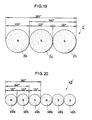
- driving magnet rotors described hereinabove are each formed as a single block on which magnetic poles are formed, they may otherwise be formed as a member including a plurality of magnetic pole segments each providing a magnetic pole as shown in a developed view of FIG. 19 or 20.
- a magnet rotor 2 ⁇ shown in FIG. 19 corresponds to the magnet rotor 2 of FIG. 2 and includes a single N magnetic pole segment 2 ⁇ N and 2 S magnetic pole segments 2 ⁇ S.
- a magnet rotor 49 ⁇ shown in FIG. 20 corresponds to the magnet rotor 49 of FIG. 8 and includes 2 N magnetic pole segments 49 ⁇ N and 4 S magnetic pole segments 49 ⁇ S.
- position detecting magnet rotor 19 and 50 are described as formed at lower end faces of the driving magnet rotors 2 and 49, respectively, they may be formed at any other location of the driving magnet rotors 2 and 49.
- the driving magnet rotors 2 and 49 may also serve as such with the position detecting magnet rotors 19 and 50 omitted.
- a suitable means may be adopted for detecting the position of the driving magnet rotor: for example, a bias is provided at a switching point of the position detecting element 26 in order to switch energization of stator coils for each electrical angle of 180 degrees; or an additional position detecting element is provided so that energization of stator coils may be switched making use of a difference in output voltage between the two position detecting elements; or else a separate position detecting magnet rotor is provided for integral rotation with a rotary shaft so that it may be detected by the position detecting element.
Landscapes
- Engineering & Computer Science (AREA)
- Power Engineering (AREA)
- Brushless Motors (AREA)
Claims (17)
- Bürstenloser Einphasenmotor umfassend
einen Feldmagneten (2) als einen Rotor mit 2P (P ist eine ganze Zahl gleich oder größer als 1) abwechselnden magnetischen Nord- und Südpolzonen, jede von entweder der magnetischen Nord- oder der Südpolzone des Feldmagneten (2) hat eine Winkelbreite gleich einem elektrischen Winkel von 120 oder etwa 120°, während jede der anderen Magnetpolzonen eine Winkelbreite gleich einem elektrischen Winkel von 240 oder etwa 240° hat, einen Statorankerkern (18) mit einer Anzahl von Statorpolen (17) daran ausgebildet in einer gegenüberliegenden Beziehung zu dem Feldmagneten (2) mit einem Luftspalt (4) dazwischen, einer Anzahl von Ankerspulen (27), die auf die Statorpole (17) des Statorankerkerns gewickelt sind und umfassend erste n (n ist eine ganze Zahl gleich oder größer als 1) Ankerspule (27-1) oder Ankerspulen für die Phase A gewickelt auf einen oder einigen der Statorpole (17-1), die an einer Stelle oder an Stellen eines elektrischen Winkels von m·(360·a) oder etwa m·(360·a) Grad ausgebildet sind (m ist eine ganze Zahl gleich oder größer als 0, und a ist eine ganze Zahl gleich oder größer als 1),
zweite n Ankerspule (27-2) oder Ankerspulen für die Phase A gewickelt in einer Wicklungsrichtung entgegen zu der der ersten Ankerspule (27-1) oder Ankerspulen für die Phase A auf einen oder einigen der Statorpole (17-3), die an einer Stelle oder Stellen umfangsförmig beabstandet durch einen Winkelabstand gleich einem elektrischen Winkel von n·(360·b-240) oder etwa n·(360·b-240) Grad (b ist eine ganze Zahl gleich oder größer als 1) von dem Statorpol oder von den Statorpolen, auf denen die erste Ankerspule oder Ankerspulen für die Phase A gewickelt sind, ausgebildet sind,
dritte n Ankerspule (27-3) oder Ankerspulen für die Phase A' gewickelt in der Wicklungsrichtung entgegen zu der der ersten Ankerspule (27-1) oder Ankerspulen für die Phase A auf einem oder einigen der Statorpole (17-3), die an einer Stelle oder Stellen umfangsförmig beabstandet durch einen Winkelabstand gleich einem elektrischen Winkel von n·(360·b-240) oder etwa n·(360·b-240) Grad von dem Statorpol oder von den Statorpolen, auf denen die erste Ankerspule (27-1) oder Ankerspulen gewickelt sind, ausgebildet sind,
vierte n Ankerspule (27-4) oder Ankerspulen für die Phase A' gewickelt in derselben Wicklungsrichtung wie die erste Ankerspule (27-1) oder Ankerspulen für die Phase A auf einer oder einigen der Statorpole (17-5), die an einer Stelle oder Stellen umfangsförmig beabstandet durch einen Winkelabstand gleich einem elektrischen Winkel von n·(360·c-120) oder etwa n·(360·c-120) Grad (c ist eine ganze Zahl gleich oder größer als 1) von dem Statorpol (17-1) oder von den Statorpolen, auf denen die erste Ankerspule (27-1) oder Ankerspulen für die Phase A gewickelt sind, ausgebildet sind,
fünfte n Ankerspule (27-5) oder Ankerspulen für die Phase B gewickelt in derselben Wicklungsrichtung wie die erste Ankerspule oder Ankerspulen für die Phase A auf einer oder einigen der Statorpole (17-4), die an einer Stelle oder Stellen umfangsförmig beabstandet zu einem Winkelabstand gleich einem elektrischen Winkel von n·(360·d-180) oder etwa n·(360·d-180) Grad (d ist eine ganze Zahl gleich oder größer als 1) von dem Statorpol (17-1) oder von den Statorpolen, auf denen die erste Ankerspule (27-1) oder Anklerspulen für die Phase A gewickelt sind, ausgebildet sind,
sechste n Ankerspule (27-6) oder Ankerspulen für die Phase B gewickelt in der Wicklungsrichtung entgegen zu der der ersten Ankerspule (27-1) oder Ankerspulen für die Phase A auf einen oder einigen der Statorpole (17-6), die an einer Stelle oder Stellen umfangsförmig beabstandet durch einen Winkelabstand gleich einem elektrischen Winkel von n·(360·e-60) oder etwa n·(360·e-60) Grad (e ist eine ganze Zahl gleich oder größer als 1) von dem Statorpol (17-1) oder von den Statorpolen, auf denen die erste Ankerspule (27-1) oder Ankerspulen für die Phase A gewickelt sind, ausgebildet sind,
siebte n Ankerspule (27-7) oder Ankerspulen für die Phase B' gewickelt in der Wicklungsrichtung entgegen zu der der ersten Ankerspule (27-1) oder Ankerspulen für die Phase A auf einen oder einigen der Statorpole (17-6), die an einer Stelle oder Stellen umfangsförmig beabstandet durch einen Winkelabstand gleich einem elektrischen Winkel von n·(360·f-180) oder etwa n·(360·f-180) Grad (f ist eine ganze Zahl gleich oder größer als 1) von dem Statorpol (17-3) oder von den Statorpolen, auf denen die dritte Ankerspule (27-3) oder Ankerspulen für die Phase A' gewickelt sind, ausgebildet sind und
achte n Ankerspule (27-8) oder Ankerspulen für die Phase B' gewickelt in der selben Wicklungsrichtung wie die erste Ankerspule (27-1) oder Ankerspulen für die Phase A auf einem oder einigen der Statorpole (17-2), die an einer Stelle oder Stellen umfangsförmig beabstandet durch einen Winkelabstand gleich einem elektrischen Winkel von n·(360·g-180) oder etwa n·(360·g-180) Grad (g ist eine ganze Zahl gleich oder größer als 1) von dem Statorpol (17-3) oder von den Statorpolen auf denen die dritte Ankerspule (27-3) oder Ankerspulen für die Phase A' gewickelt sind, ausgebildet sind und
eine elektrische Schaltung (25) zum Wahrnehmen der Stellung des Feldmagneten (2), um die Ankerspulen (27A,27A') für die Phasen A und A' und die Ankerspulen (27B,27B') für die Phasen B und B' abwechselnd um einen elektrischen Winkel von 180 oder etwa 180° zu erregen. - Bürstenloser Einphasenmotor nach Anspruch 1,
wobei die Statorpole (17) des Statorankerkerns (18), auf dem die Statorspulen (27) gewickelt sind, in einer umfangsförmigen gleichbeabstandeten Beziehung voneinander ausgebildet sind. - Bürstenloser Einphasenmotor nach Anspruch 1,
wobei die Statorpole (17) den Statorankerkern (18), auf dem die Ankerspulen gewickelt sind, in einer umfangsförmigen gleichbeabstandeten Beziehung voneinander durch einen Winkelabstand gleich einem elektrischen Winkel von 60 oder etwa 60° ausgebildet sind. - Bürstenloser Einphasenmotor nach Anspruch 1,
wobei jede der Statorpole (17) des Statorankerkerns (18) eine oder mehrere Hilfsnuten (102) hat, ausgebildet in einer gleichbeabstandeten Beziehung daran, wobei die Hilfsnuten (102) der Statorpole (17) eine gleiche oder im wesentlichen gleiche Winkelbreite wie die Winkelbreite der Luftspalte (103) haben, die zwischen den Statorpolen begrenzt sind, wobei die Hilfsnuten (102) und die Luftspalte (103) zwischen den Statorpolen mit einem gleichen Winkelabstand voneinander beabstandet sind. - Bürstenloser Einphasenmotor nach Anspruch 1,
wobei der Statorankerkern (76), auf dem die Ankerspulen (47) für die Phasen A, A',B und B' gewickelt sind, einen Hilfsstatorpol oder die Hilfsstatorpole (47-2,4,6,7,9 und 11) hat, die zwischen einigen selektiven, angrenzenden Statorpolen (47), auf denen die Ankerspulen (75) gewikkelt sind, ausgebildet sind. - Bürstenloser Einphasenmotor nach Anspruch 5,
wobei die Statorpole (47), auf denen die Statorspulen (75) gewickelt sind und der Hilfsstatorpol oder die Hilfsstatorpole in einer umfangsförmigen gleichbeabstandeten Beziehung voneinander ausgebildet sind. - Bürstenloser Einphasenmotor nach Anspruch 6,
wobei die Statorpole (47), auf der die Statorspulen (75) gewickelt sind und der Hilfsstatorpol oder die Hilfsstatorpole im allgemeinen in einer umfangsförmigen gleichbeabstandeten Beziehung voneinander ausgebildet sind durch einen Winkelabstand entsprechend einem elektrischen Winkel von 60 oder etwa 60°. - Bürstenloser Einphasenmotor nach Anspruch 5,
wobei jeder der Statorpole (47'), auf dem die Statorspulen (75) gewickelt sind und der Hilfsstatorpol oder die Hilfsstatorpole eine oder mehrere Hilfsnuten (102) haben, ausgebildet in einer gleichbeabstandeten Beziehung daran, wobei die Hilfsnuten (102) der Statorpole (47) und der Hilfsstatorpole eine gleiche oder im wesentlichen gleiche Winkelbreite wie die Winkelbreite eines Luftspaltes (103) haben, begrenzt zwischen jeden der angrenzenden Statorpole und Hilfsstatorpole, wobei die Hilfsnuten (102) und die Luftspalte (103) zwischen den Statorpolen durch einen gleichen Winkelabstand voneinder beabstandet sind. - Bürstenloser Einphasenmotor nach Anspruch 1,
wobei der Feldmagnet (2) als ein Rotor vorgesehen ist mit zwei magnetischen Nord- und Südpolzonen, wobei eine der magnetischen Nord- und Südpolzonen des Feldmagneten eine Winkelbreite gleich einem elektrischen Winkel von 120 oder etwa 120° hat, während die andere magnetische Polzone eine Winkelbreite gleich einem elektrischen Winkel von 240 oder etwa 240° hat, und der Statorankerkern (18) sechs Statorpole (17) hat, die daran in einer umfangsförmigen gleichbeabstandeten Beziehung voneinander und in einer gegenüberliegenden Beziehung zu dem ersten Feldmagnet (2) mit einem radialen Luftspalt (4) dazwischen ausgebildet sind, wobei die Ankerspulen umfassen
eine erste Ankerspule (27-1) für die Phase A gewickelt auf einem der Statorpole (17-1), der an einer Stelle eines elektrischen Winkels von 360° ausgebildet ist,
eine zweite Ankerspule (27-2) für die Phase A gewickelt in der Wicklungsrichtung entgegen zu der der ersten Ankerspule für die Phase A auf einem der Statorpole (17-3), der an einer Stelle umfangsförmig beabstandet durch einen Winkelabstand gleich einem elektrischen Winkel von 120 oder etwa 120° von dem Statorpol, auf dem die erste Ankerspule für die Phase A gewickelt ist, ausgebildet ist, eine dritte Ankerspule (27-3) für die Phase A' gewickelt in der Wicklungsrichtung entgegen zu der der ersten Ankerspule auf dem Statorpol (17-3), auf dem die zweite Ankerspule für die Phase A gewickelt ist,
eine vierte Ankerspule (27-4) für die Phase A' gewickelt in der selben Wicklungsrichtung wie die erste Ankerspule für die Phase A auf einem der Statorpole (17-5), der an einer Stelle umfangsförmig beabstandet durch einen Winkelabstand gleich einem elektrischen Winkel von 240 oder etwa 240° von dem Statorpol, auf dem die erste Ankerspule für die Phase A gewickelt ist, ausgebildet ist,
eine fünfte Ankerspule (27-5) für die Phase B gewickelt in derselben Wicklungsrichtung wie die erste Ankerspule auf einem der Statorpole (17-4), der an einer Stelle umfangsförmig beabstandet durch einen Winkelabstand gleich einem elektrischen Winkel von 180 oder etwa 180° von dem Statorpol, auf dem die erste Ankerspule für die Phase A gewickelt ist, ausgebildet ist,
eine sechste Ankerspule (27-6) für die Phase B gewickelt in der Wicklungsrichtung entgegen zu der der ersten Ankerspule für die Phase A auf einem der Statorpole (17-6), der an einer Stelle umfangsförmig beabstandet durch einen Winkelabstand gleich einem elektrischen Winkel von 60 oder etwa 60° von dem Statorpol, auf dem die erste Ankerspule für die Phase A gewickelt ist, ausgebildet ist,
eine siebte Ankerspule (27-7) für die Phase B' gewickelt in der Wicklungsrichtung entgegen zu der der vierten Ankerspule auf dem Statorpol (17-6), auf dem die sechste Ankerspule gewickelt ist, und
eine achte Ankerspule (27-8) für die Phase B' gewickelt in derselben Wicklungsrichtung wie die erste Ankerspule auf einem der Statorpole (17-2), der an einer Stelle umfangsförmig beabstandet durch einen Winkelabstand gleich einem elektrischen Winkel von 60 oder etwa 60° von dem Statorpol, auf dem die dritte Ankerspule gewickelt ist, ausgebildet ist, wobei die elektrische Schaltung (25) betriebsfähig ist zum Wahrnehmen der Stellung des Feldmagneten zum Erregen der Ankerspulen für die Phasen A und A' und der Ankerspulen für die Phasen B und B' abwechselnd um einen elektrischen Winkel von 180 oder etwa 180°. - Bürstenloser Einphasenmotor nach Anspruch 1,
wobei der Feldmagnet (49) als ein Rotor vorgesehen ist mit vier abwechselnden magnetischen Nord- und Südpolzonen, jede von entweder der magnetischen Nord- oder Südpolzonen des Feldmagneten (49) hat eine Winkelbreite gleich einem elektrischen Winkel von 120 oder etwa 120°, während jede der anderen magnetischen Polzonen eine Winkelbreite gleich einem elektrischen Winkel von 240 oder etwa 240° hat, und der Statorankerkern (46) eine Anzahl von Statorpolen (47) hat, die daran in einer gegenüberliegenden Beziehung zu dem Feldmagneten mit einem Luftspalt (48) dazwischen ausgebildet sind, wobei die Ankerspulen umfassen
eine erste Ankerspule (51-1) für die Phase A gewickelt auf einem der Statorpole (47-1), die an einer Stelle eines elektrischen Winkels von m·360 oder etwa m·360 Grad (hier: m=0) ausgebildet sind,
eine zweite Ankerspule (51-2) für die Phase A gewickelt in der Wicklungsrichtung entgegen zu der ersten Ankerspule (51-1) für die Phase A auf einem der Statorpole (47-3), die an einer Stelle umfangsförmig beabstandet durch einen Winkelabstand gleich einem elektrischen Winkel von 120 oder etwa 120° von dem Statorpol (47-1), auf dem die erste Ankerspule für die Phase A gewickelt ist, ausgebildet ist,
eine dritte Ankerspule (51-3) für die Phase A' gewickelt in der Wicklungsrichtung entgegen zu der ersten Ankerspule (51-1) für die Phase A auf dem Statorpol (47-3), auf dem die zweite Ankerspule (51-2) für die Phase A gewickelt ist,
eine vierte Ankerspule (51-4) für die Phase A' gewickelt in derselben Wicklungsrichtung wie die erste Ankerspule (51-1) für die Phase A auf einem der Statorpole (47-5), der an einer Stelle umfangsförmig beabstandet durch einen Winkelabstand gleich einem elektrischen Winkel von n·(360·c-120) oder etwa n·(360·c-120) Grad (hier: n=1 und c=1) von dem Statorpol (47-1), auf dem die erste Ankerspule für die Phase A gewickelt ist, ausgebildet ist, eine fünfte Ankerspule (51-5) für die Phase A gewickelt in derselben Wicklungsrichtung wie die erste Ankerspule (51-1) für die Phase A auf einem der Statorpole (47-7), der an einer Stelle umfangsförmig beabstandet durch einen Winkelabstand gleich einem elektrischen Winkel von m·360·a oder etwa m·360·a Grad (hier: m=1 und a=1) von dem Statorpol (47-1), auf dem die ersten Ankerspule für die Phase A gewickelt ist, ausgebildet ist,
eine sechste Ankerspule (51-6) für die Phase A gewickelt in der Wicklungsrichtung entgegen zu der der ersten Ankerspule (51-1) auf einem der Statorpole (47-9), der an einer Stelle umfangsförmig beabstandet durch einen Winkelabstand gleich einem elektrischen Winkel von n·(360·b-240) oder etwa n·(360·b-240) Grad (hier: n=4,b=1) von dem Statorpol (47-1), auf dem die erste Ankerspule für die Phase A gewickelt ist, ausgebildet ist,
eine siebte Ankerspule (51-7) für die Phase A' gewickelt in der Wicklungsrichtung entgegen zu der ersten Ankerspule auf dem Statorpol (47-9) auf dem die sechste Ankerspule (51-6) gewickelt ist,
eine achte Ankerspule (51-8) für die Phase A' gewickelt in derselben Wicklungsrichtung wie die erste Ankerspule für die Phase A auf einem der Statorpole (47-11), der an einer Stelle umfangsförmig beabstandet durch einen Winkelabstand gleich einem elektrischen Winkel von n·(360·b-240) oder etwa n·(360·b-240) Grad (hier: n=5, b=1) von dem Statorpol (47-1), auf dem die erste Ankerspule für die Phase A gewickelt ist, ausgebildet ist,
eine neunte Ankerspule (51-9) für die Phase B gewickelt in derselben Richtung wie die erste Ankerspule für die Phase A auf einem der Statorpole (47-10), der an einer Stelle umfangsförmig beabstandet durch einen Winkelabstand gleich einem elektrischen Winkel von n·(360·d-180) oder etwa n·(360·d-180) Grad (hier: n=1, d=1) von dem Statorpol (47-1), auf dem die erste Ankerspule für die Phase A gewickelt ist, ausgebildet ist,
eine zehnte Ankerspule (51-10) für die Phase B gewickelt in der Wicklungsrichtung entgegen zu der der ersten Ankerspule für die Phase A auf einem der Statorpole (47-12), der an einer Stelle umfangsförmig beabstandet durch einen Winkelabstand gleich einem elektrischen Winkel von n·(360·e-180) oder etwa n·(360·e-180) Grad (hier: n=3, e=1) von dem Statorpol, auf dem die erste Ankerspule für die Phase A gewickelt ist, ausgebildet ist,
eine elfte Ankerspule (51-11) für die Phase B' gewickelt in der Wicklungsrichtung entgegen zu der der ersten Ankerspule für die Phase A auf dem Statorpol (47-12), auf dem die zehnte Ankerspule (57-10) für die Phase B gewikkelt ist,
eine zwölfte Ankerspule (51-12) für die Phase B' gewikkelt in derselben Wicklungsrichtung wie die erste Ankerspule für die Phase A auf einem der Statorpole (47-2), der an einer Stelle umfangsförmig beabstandet durch einen Winkelabstand gleich einem elektrischen Winkel von n·(360·g-240) oder etwa n·(360·g-240) Grad (hier: n=1 und g=1) von dem Statorpol (47-12), auf dem die elfte Ankerspule (51-11) für die Phase B' gewickelt ist, ausgebildet ist,
eine dreizehnte Ankerspule (51-13) für die Phase B gewickelt in derselben Wicklungsrichtung wie die erste Ankerspule für die Phase A auf einem der Statorpole (47-4), der an einer Stelle umfangsförmig beabstandet durch einen Winkelabstand gleich einem elektrischen Winkel von n·(360·d-180) oder etwa n·(360·d-180) Grad (hier: n=1 und d=1) von dem Statorpol, auf dem die erste Ankerspule für die Phase A gewickelt ist, ausgebildet ist,
eine vierzehnte Ankerspule (51-14) für die Phase B gewunden in der Wicklungsrichtung entgegen zu der der ersten Ankerspule für die Phase A auf einem der Statorpole (47-6), der an einer Stelle umfangsförmig beabstandet durch einen Winkelabstand gleich einem elektrischen Winkel von m·360·a oder etwa m·360·a Grad (hier: m=1 und a=1) von dem Statorpol, auf dem die elfte Ankerspule (51-11) für die Phase B gewickelt ist, ausgebildet ist,
eine fünfzehnte Ankerspule (51-15) für die Phase B' gewickelt in die Wicklungsrichtung entgegen zu der der ersten Ankerspule für die Phase A auf dem Statorpol (47-6), auf dem die vierzehnte Ankerspule für die Phase B gewickelt ist, und
eine sechzehnte Ankerspule (51-16) für die Phase B' gewickelt in dieselbe Wicklungsrichtung wie die erste Ankerspule für die Phase A auf einen der Statorpole (47-8), der an einer Stelle umfangsförmig beabstandet durch einen Winkelabstand gleich einem elektrischen Winkel von n·(360·g-180) oder etwa n·(360·g-180) Grad (hier: n=1 und g=1) von dem Statorpol (47-5), auf dem die vierte Ankerspule (51-4) für die Phase A gewickelt ist, ausgebildet ist, wobei die elektrische Schaltung (44) betriebsfähig ist zum Wahrnehmen der Stellung des Feldmagneten zum Erregen der Ankerspulen für die Phasen A und A' und der Ankerspulen für die Phasen B und B' abwechselnd für einen elektrischen Winkel von 180 oder etwa 180°. - Bürstenloser Einphasenmotor nach Anspruch 1,
wobei der Feldmagnet (49) als ein Rotor vorgesehen ist mit vier abwechselnden magnetischen Nord- und Südpolzonen, jede von entweder der magnetischen Nord- oder Südpolzone des Feldmagneten hat eine Winkelbreite gleich einem elektrischen Winkel von 120 oder etwa 120°, während jede der anderen magnetischen Polzonen eine Winkelbreite gleich einem elektrischen Winkel von 240 oder etwa 240° hat, und die Statorankerspule (76) eine Anzahl von Statorpolen (47) daran ausgebildet hat in einer gegenüberliegenden Beziehung zu dem Feldmagneten (49) mit einem Luftspalt dazwischen, wobei die Ankerspulen umfassen eine erste Ankerspule (75-1) für die Phase A gewickelt auf einem der Statorpole (47-1), der an einer Stelle eines elektrischen Winkels von m·360·a oder etwa m·360·a Grad (hier: m=1 und a=1), ausgebildet ist,
eine zweite Ankerspule (75-2) für die Phase A gewickelt in die Wicklungsrichtung entgegen zu der der ersten Ankerspule für die Phase A auf einem der Statorpole (47-3), der an einer Stelle umfangsförmig beabstandet zu einem Winkelabstand gleich einem elektrischen Winkel von 120 oder etwa 120° von dem Statorpol, auf dem die erste Ankerspule für die Phase A gewickelt ist, ausgebildet ist,
eine dritte Ankerspule (75-3) für die Phase A' gewickelt in der Wicklungsrichtung entgegen zu der der ersten Ankerspule für die Phase A auf dem Statorpol (47-3), auf dem die zweite Ankerspule für die Phase A gewickelt ist, eine vierte Ankerspule (75-4) für die Phase A' gewickelt in derselben Wicklungsrichtung wie die erste Ankerspule für die Phase A auf einem der Statorpole (47-5), der an einer Stelle umfangsförmig beabstandet durch einen Winkelabstand gleich einem elektrischen Winkel von n·(360·b-240) oder etwa n·(360·b-240) Grad (hier: n=1 und b=1) von dem Statorpol, auf dem die erste Ankerspule für die Phase A gewickelt ist, ausgebildet ist,
eine fünfte Ankerspule (75-5) für die Phase B gewickelt in derselben Wicklungsrichtung wie die erste Ankerspule für die Phase A auf einem der Statorpole (47-10), der an einer Stelle umfangsförmig beabstandet durch einen Winkelabstand gleich einem elektrischen Winkel von n·(360·d-180) oder etwa n·(360·d-180) Grad (hier: n=1 und d=1) von dem Statorpol, auf dem die erste Ankerspule für die Phase A gewickelt ist, ausgebildet ist,
eine sechste Ankerspule (75-6) für die Phase B gewickelt in der Wicklungsrichtung entgegen zu der der ersten Ankerspule für die Phase A auf einem der Statorpole (47-12), der an einer Stelle umfangsförmig beabstandet durch einen Winkelabstand gleich einem elektrischen Winkel von n·(360·e-60) oder etwa n·(360·e-60) Grad (hier: n=1 und e=1) von dem Statorpol, auf dem die erste Ankerspule für die Phase A gewickelt ist, ausgebildet ist,
eine siebte Ankerspule (75-7) für die Phase B' gewickelt in der Wicklungsrichtung entgegen zu der der ersten Ankerspule für die Phase A auf dem Statorpol (47-12), auf dem die sechste Ankerspule gewickelt ist, und
eine achte Ankerspule (75-8) für die Phase B' gewickelt in derselben Wicklungsrichtung wie die erste Ankerspule für die Phase A auf einem der Statorpole (47-8), der an einer Stelle umfangsförmig beabstandet durch einen Winkelabstand gleich einem elektrischen Winkel von n·(360·f-180) oder etwa n·(360·f-180) Grad (hier: n=1 und f=1) von dem Statorpol, auf dem die vierte Ankerspule für die Phase A' gewickelt ist, ausgebildet ist,
wobei die elektrische Schaltung (44) betriebsfähig ist zum Wahrnehmen der Stellung des Feldmagneten zum Erregen der Ankerspulen für die Phasen A und A' und der Ankerspulen für die Phasen B und B' abwechselnd um einen elektrischen Winkel von 180 oder etwa 180°. - Bürstenloser Einphasenmotor nach Anspruch 1, ferner umfassend
einen stellungswahrnehmenden Magnetrotor (19) mit 2P abwechselnden magnetischen Nord- und Südpolzonen, wobei jede eine Winkelbreite gleich einem elektrischen Winkel von 180 oder etwa 180° hat, und einem einzigen Magnetsensor (26) zum Wahrnehmen eines magnetischen Pols des stellungswahrnehmenden Magnetrotors (19) zum Ausgeben eines Signals an die elektrische Schaltung (25) zum Auslösen, daß die Ankerspulen (27,75) ein Drehmoment in eine vorbestimmte Richtung erzeugen. - Bürstenloser Einphasenmotor nach Anspruch 12,
wobei der stellungswahrnehmende Magnetrotor (19) ausgebildet ist durch Magnetisierung eines magnetisierbaren Körpers des Feldmagneten (2). - Bürstenloser Einphasenmotor nach Anspruch 1,
wobei der Statorankerkern (18) ein Element (105) für die Verminderung eines Versatzdrehmomentes umfaßt, das durch die Statorpole und Spalten zwischen den Statorpolen verursacht wird. - Bürstenloser Einphasenmotor nach Anspruch 14,
wobei das Element ein magnetisches Element (105) in Form eines Ringes mit einer geringen Stärke ist und an eine Stirnfläche des Statorankerkerns (18) gegenüberliegend zu dem Feldmagneten (2) mit dem Luftspalt (4) befestigt ist, der dazwischen angeordnet ist. - Bürstenloser Einphasenmotor nach Anspruch 15,
wobei das Magnetelement (105) in der Form eines Ringes an eine Umfangsstirnfläche des Statorankerkerns (18) gegenüberliegend zu dem Feldmagneten (2) mit dem Luftspalt (4) befestigt ist, der dazwischen angeordnet ist, wo der bürstenlose Einphasenmotor vom radialen Luftspalttyp ist. - Bürstenloser Einphasenmotor nach Anspruch 16,
wobei das magnetische Element (105) in der Form eines Ringes an eine äußere Umfangsstirnfläche des Statorankerkerns (18) gegenüberliegend zu dem Feldmagneten (2) mit dem Luftspalt (4) befestigt ist, der dazwischen angeordnet ist, wo der bürstenlose Einphasenmotor vom radialen Luftspalttyp und auch vom Außenrotortyp ist.
Priority Applications (2)
| Application Number | Priority Date | Filing Date | Title |
|---|---|---|---|
| DE8686114960T DE3684923D1 (de) | 1986-10-28 | 1986-10-28 | Buerstenloser einphasenmotor. |
| EP86114960A EP0265539B1 (de) | 1986-10-28 | 1986-10-28 | Bürstenloser Einphasenmotor |
Applications Claiming Priority (1)
| Application Number | Priority Date | Filing Date | Title |
|---|---|---|---|
| EP86114960A EP0265539B1 (de) | 1986-10-28 | 1986-10-28 | Bürstenloser Einphasenmotor |
Publications (2)
| Publication Number | Publication Date |
|---|---|
| EP0265539A1 EP0265539A1 (de) | 1988-05-04 |
| EP0265539B1 true EP0265539B1 (de) | 1992-04-15 |
Family
ID=8195538
Family Applications (1)
| Application Number | Title | Priority Date | Filing Date |
|---|---|---|---|
| EP86114960A Expired - Lifetime EP0265539B1 (de) | 1986-10-28 | 1986-10-28 | Bürstenloser Einphasenmotor |
Country Status (2)
| Country | Link |
|---|---|
| EP (1) | EP0265539B1 (de) |
| DE (1) | DE3684923D1 (de) |
Families Citing this family (2)
| Publication number | Priority date | Publication date | Assignee | Title |
|---|---|---|---|---|
| CA2642390C (en) | 2006-03-07 | 2014-09-30 | Pacific Brands Clothing Pty Ltd. | A sock |
| CN108539947A (zh) * | 2018-04-20 | 2018-09-14 | 峰岹科技(深圳)有限公司 | 单相永磁交流电机 |
Family Cites Families (3)
| Publication number | Priority date | Publication date | Assignee | Title |
|---|---|---|---|---|
| DE1563266A1 (de) * | 1966-10-28 | 1970-04-09 | Licentia Gmbh | Buerstenloser Gleichstrommotor mit Dauermagnetlaeufer |
| CH650366A5 (de) * | 1980-07-18 | 1985-07-15 | Papst Motoren Kg | Kollektorloser gleichstromaussenlaeufermotor. |
| DE3526007C2 (de) * | 1984-07-20 | 1999-11-11 | Papst Licensing Gmbh & Co Kg | Schaltungsanordnung zum Ansteuern eines kollektorlosen, an ein Gleichstromnetz angeschlossenen Gleichsstrommotors |
-
1986
- 1986-10-28 EP EP86114960A patent/EP0265539B1/de not_active Expired - Lifetime
- 1986-10-28 DE DE8686114960T patent/DE3684923D1/de not_active Expired - Fee Related
Also Published As
| Publication number | Publication date |
|---|---|
| DE3684923D1 (de) | 1992-05-21 |
| EP0265539A1 (de) | 1988-05-04 |
Similar Documents
| Publication | Publication Date | Title |
|---|---|---|
| US4739203A (en) | Single-phase brushless motor with cogging features | |
| US4737674A (en) | Single phase brushless motor with a core | |
| US4755699A (en) | Enclosed miniature motor | |
| US4804873A (en) | Unidirectional brushless motor | |
| US4707645A (en) | Single-phase brushless motor | |
| JPS61102163A (ja) | 電子的に転流される無集電子直流モータ | |
| KR970060638A (ko) | 브러시리스 직류모터 | |
| ATE72614T1 (de) | Ansteuerschaltungen fuer buerstenlose motoren. | |
| US5689147A (en) | Brushless motor | |
| TR199802748T2 (xx) | Bir çamaşır makinası tamburunun doğrudan tahriki için elektronik komütasyonlu motor. | |
| EP0265539B1 (de) | Bürstenloser Einphasenmotor | |
| JPH0444504B2 (de) | ||
| JP3333538B2 (ja) | 無刷子電動機 | |
| JPH0210781Y2 (de) | ||
| JP3447795B2 (ja) | ブラシレスモータ | |
| JP3633965B2 (ja) | ブラシレスモータ | |
| KR900007275Y1 (ko) | 자기저항이 없는 지름방향 공극형 단상 브러시리스 모터 | |
| JPH0815388B2 (ja) | Dcブラシレスモ−タ | |
| JPH05176514A (ja) | 無刷子電動機 | |
| JPH0723028Y2 (ja) | ブラシレスモ−タ | |
| JPS6324978U (de) | ||
| JP2884580B2 (ja) | 無刷子直流モータ | |
| JPH06165464A (ja) | ブラシレスモータ | |
| JPS63220754A (ja) | モ−タ | |
| JPH0182673U (de) |
Legal Events
| Date | Code | Title | Description |
|---|---|---|---|
| PUAI | Public reference made under article 153(3) epc to a published international application that has entered the european phase |
Free format text: ORIGINAL CODE: 0009012 |
|
| AK | Designated contracting states |
Kind code of ref document: A1 Designated state(s): CH DE FR GB LI |
|
| 17P | Request for examination filed |
Effective date: 19880919 |
|
| 17Q | First examination report despatched |
Effective date: 19901018 |
|
| GRAA | (expected) grant |
Free format text: ORIGINAL CODE: 0009210 |
|
| AK | Designated contracting states |
Kind code of ref document: B1 Designated state(s): CH DE FR GB LI |
|
| REF | Corresponds to: |
Ref document number: 3684923 Country of ref document: DE Date of ref document: 19920521 |
|
| ET | Fr: translation filed | ||
| PLBE | No opposition filed within time limit |
Free format text: ORIGINAL CODE: 0009261 |
|
| STAA | Information on the status of an ep patent application or granted ep patent |
Free format text: STATUS: NO OPPOSITION FILED WITHIN TIME LIMIT |
|
| 26N | No opposition filed | ||
| PGFP | Annual fee paid to national office [announced via postgrant information from national office to epo] |
Ref country code: FR Payment date: 19931021 Year of fee payment: 8 |
|
| PGFP | Annual fee paid to national office [announced via postgrant information from national office to epo] |
Ref country code: CH Payment date: 19931025 Year of fee payment: 8 |
|
| PGFP | Annual fee paid to national office [announced via postgrant information from national office to epo] |
Ref country code: GB Payment date: 19931026 Year of fee payment: 8 |
|
| PGFP | Annual fee paid to national office [announced via postgrant information from national office to epo] |
Ref country code: DE Payment date: 19931228 Year of fee payment: 8 |
|
| PG25 | Lapsed in a contracting state [announced via postgrant information from national office to epo] |
Ref country code: GB Effective date: 19941028 |
|
| PG25 | Lapsed in a contracting state [announced via postgrant information from national office to epo] |
Ref country code: LI Effective date: 19941031 Ref country code: CH Effective date: 19941031 |
|
| GBPC | Gb: european patent ceased through non-payment of renewal fee |
Effective date: 19941028 |
|
| PG25 | Lapsed in a contracting state [announced via postgrant information from national office to epo] |
Ref country code: FR Effective date: 19950630 |
|
| REG | Reference to a national code |
Ref country code: CH Ref legal event code: PL |
|
| PG25 | Lapsed in a contracting state [announced via postgrant information from national office to epo] |
Ref country code: DE Effective date: 19950701 |
|
| REG | Reference to a national code |
Ref country code: FR Ref legal event code: ST |