EP0266052A2 - Elektrischer Detonator - Google Patents
Elektrischer Detonator Download PDFInfo
- Publication number
- EP0266052A2 EP0266052A2 EP87308371A EP87308371A EP0266052A2 EP 0266052 A2 EP0266052 A2 EP 0266052A2 EP 87308371 A EP87308371 A EP 87308371A EP 87308371 A EP87308371 A EP 87308371A EP 0266052 A2 EP0266052 A2 EP 0266052A2
- Authority
- EP
- European Patent Office
- Prior art keywords
- shell
- plug
- conductors
- conductor
- detonator
- Prior art date
- Legal status (The legal status is an assumption and is not a legal conclusion. Google has not performed a legal analysis and makes no representation as to the accuracy of the status listed.)
- Withdrawn
Links
- 239000004020 conductor Substances 0.000 claims abstract description 36
- 230000003068 static effect Effects 0.000 claims abstract description 22
- 238000009825 accumulation Methods 0.000 claims abstract 4
- 239000002360 explosive Substances 0.000 claims description 27
- 230000000977 initiatory effect Effects 0.000 claims description 10
- 238000000034 method Methods 0.000 claims description 4
- 238000007599 discharging Methods 0.000 claims 1
- 238000004880 explosion Methods 0.000 claims 1
- 238000003780 insertion Methods 0.000 claims 1
- 230000037431 insertion Effects 0.000 claims 1
- 230000005611 electricity Effects 0.000 abstract description 12
- 239000000463 material Substances 0.000 description 10
- 238000005474 detonation Methods 0.000 description 5
- 230000002028 premature Effects 0.000 description 4
- 238000007789 sealing Methods 0.000 description 4
- 238000013461 design Methods 0.000 description 3
- 230000001629 suppression Effects 0.000 description 3
- XAGFODPZIPBFFR-UHFFFAOYSA-N aluminium Chemical compound [Al] XAGFODPZIPBFFR-UHFFFAOYSA-N 0.000 description 2
- 230000015556 catabolic process Effects 0.000 description 2
- 229920001971 elastomer Polymers 0.000 description 2
- 238000003754 machining Methods 0.000 description 2
- 238000012986 modification Methods 0.000 description 2
- 230000004048 modification Effects 0.000 description 2
- 238000000926 separation method Methods 0.000 description 2
- 229910000906 Bronze Inorganic materials 0.000 description 1
- 208000027418 Wounds and injury Diseases 0.000 description 1
- 229910045601 alloy Inorganic materials 0.000 description 1
- 239000000956 alloy Substances 0.000 description 1
- 239000004411 aluminium Substances 0.000 description 1
- 229910052782 aluminium Inorganic materials 0.000 description 1
- 238000013459 approach Methods 0.000 description 1
- 238000005422 blasting Methods 0.000 description 1
- 239000010974 bronze Substances 0.000 description 1
- 238000010276 construction Methods 0.000 description 1
- 239000000356 contaminant Substances 0.000 description 1
- 238000007796 conventional method Methods 0.000 description 1
- KUNSUQLRTQLHQQ-UHFFFAOYSA-N copper tin Chemical compound [Cu].[Sn] KUNSUQLRTQLHQQ-UHFFFAOYSA-N 0.000 description 1
- 230000006378 damage Effects 0.000 description 1
- 238000010304 firing Methods 0.000 description 1
- 208000014674 injury Diseases 0.000 description 1
- 238000000465 moulding Methods 0.000 description 1
- 239000012811 non-conductive material Substances 0.000 description 1
- 229920001568 phenolic resin Polymers 0.000 description 1
- 239000004033 plastic Substances 0.000 description 1
- XLYOFNOQVPJJNP-UHFFFAOYSA-N water Substances O XLYOFNOQVPJJNP-UHFFFAOYSA-N 0.000 description 1
Images
Classifications
-
- F—MECHANICAL ENGINEERING; LIGHTING; HEATING; WEAPONS; BLASTING
- F42—AMMUNITION; BLASTING
- F42B—EXPLOSIVE CHARGES, e.g. FOR BLASTING, FIREWORKS, AMMUNITION
- F42B3/00—Blasting cartridges, i.e. case and explosive
- F42B3/10—Initiators therefor
- F42B3/18—Safety initiators resistant to premature firing by static electricity or stray currents
Definitions
- This invention relates to electric detonators generally and more particularly to a static electricity suppression arrangement for use in two-wire electric detonators.
- An electric detonator (blasting cap) converts electrical energy into heat energy which, in turn, produces an explosive force capable of detonating a large explosive charge.
- the electrical energy is supplied to the detonator by two electrical conductors, called leg wires, which typically enter the detonator through a rubber or plastic sealing plug.
- leg wires which typically enter the detonator through a rubber or plastic sealing plug.
- the ends of the leg wires inside the detonator are joined together by a high resistant "bridge wire" which, when sufficient current flows through it, heats up to ignite a heat sensitive material which surrounds the bridge wire. This, in turn, ignites delay fuse elements to thus ignite or detonate a primary explosive charge which then detonates a base explosive charge.
- the explosive force developed by the base explosive charge is used to detonate the aforementioned large explosive charge.
- the explosive charge's delay fuse elements, heat sensitive material, and sealing plug are encased in a cylindrical shell made of an electrically conductive material such as aluminium, bronze, etc.
- the plug is positioned in one end of the shell to hold the leg wires in positions spaced from the shell wall, and to guide the leg wires to the heat sensitive material.
- an electric detonator which includes an electrically conductive shell, an explosive initiating device disposed in the shell for producing an explosive in response to electrical current, an electrically non-conductive plug disposed within the shell at one end, and a pair of conductors which extend through the plug into the shell and are coupled to the explosive initiating device for carrying electrical current to the device.
- the electrical conductors extend initially into the plug disposed apart from one another and from the shell, and then a portion of each conductor is bent to extend to locations near the shell and near one another. From the locations, the conductors extend back away from the shell and from one another to the explosive initiating device.
- Static charge build-up on one of the conductors when it reaches a sufficient level, will discharge from that conductor to the shell.
- the spark created by the discharge ionizes the air gap and triggers a discharge from the other conductor to the shell so that electrical energy produced by static charge build-up is prevented from reaching the explosive initiating device.
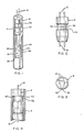
- an electric detonator made in accordance with the present invention and including an electrically conductive housing or shell 4 made, for example, of aluminium bronze, or an alloy thereof.
- the shell 4 is formed as an elongate hollow cylinder to contain a sealing plug 8 at the upper end thereof.
- the sealing plug 8 is placed in the shell 4 to receive and guide a pair of leg wires 12 toward the interior of the shell and to prevent entry into the shell of moisture, water or contaminants.
- the plug 8 is made of a non-conductive material such as rubber or phenolic plastic. Often the shell 4 is crimped about the plug 8 to securely hold it in place and complete the water-resistant seal.
- the leg wires 12 are provided for conducting electrical current from a current source (not shown) to the interior of the shell 4 to an explosive initiating device 16.
- the device 16 is of conventional design and includes a bridge wire 20 which joins the two lower ends of the leg wires 12, a heat sensitive material 24 surrounding the bridge wire, a delay fuse element 26, a primary explosive charge 28, and a base explosive charge 34. When sufficient current is supplied to the bridge wire 20, it heats up to ignite the heat sensitive material 24 which, in turn, ignites the delay fuse element 26, the primary explosive charge 28 and then the secondary base explosive charge 34 to ultimately detonate a large working explosive charge.
- the heat sensitive material, primary explosive charge, delay fuse element, and base explosive charge are all conventional and well known.
- the leg wires 12, as they enter the plug 8, are spaced apart from one another and from the shell 4 and positioned somewhat centrally in the plug. After extending a short distance into the plug, the leg wires then bend or curve outwardly toward the shell (see Figs. 2-4) and towards each other to locations 32 and 36 where the wires are exposed at the exterior surface of the plug.
- the exterior surface where the locations 32 and 36 expose the leg wires is formed into a groove or recess 40 which circumscribes the plug. After reaching the exterior surface of the groove 40 of the plug 8, the leg wires curve or bend back toward the centre of the plug and then downwardly to emerge out from the bottom end of the plug. From there, the leg wires extend into the explosive initiating device 16 where the ends of the leg wires are joined by the bridge wire 20.
- the construction of the plug 8 and leg wires 12 shown in the drawings facilitates locating the exposed portions 32 and 36 of the leg wires 12 a precise distance from the shell 4. This distance is carefully selected to ensure discharge of static electricity from the leg wires to the shell. Additionally, the locations 32 and 36 are spaced a predetermined distance from one another for reasons that will be explained momentarily.
- the plug 8 advantageously is constructed using a mould in which the leg wires 12 are prepositioned generally with the curved or bent sections extending to near or at the interior surface of the mould.
- the mould is formed to produce a plug without the groove or recess 40.
- material for making the plug is poured into or applied to the mould to surround the leg wires.
- the plug 8 is removed and then the groove 40 is formed by machining, cutting or the like to the desired depth. In the process of machining the groove 40, the portions 32 and 36 of the leg wires are exposed to the exterior which means that some of the wire material may be removed along with removal of the plug material.
- a separation between the exposed locations 32 and 36 measured from the two adjacent edges of the locations of from between about 0.13 mm (0.005 inch) to 0.66 mm (0.026 inch). A separation greater than this may be desired for detonators having a higher firing current and/or higher voltage breakdown levels in the ignition system. It has also been found advantageous to provide an area of exposed wire for the locations 32 and 36 of about 0.76 mm by 0.76 mm (0.030 by 0.030 inch), but likewise may be varied for different detonator designs.
- the ionized air provides improved conductivity between the other leg wire and the shell 4 causing it to also discharge to the shell through the ionized air.
- a discharge from one wire will ionize the air surrounding the other wire and vice versa. If the exposed locations 32 and 36 were not in close proximity, then discharge from one wire to the shell 4 would not produce ionization around the other wire.
- a voltage imbalance would then be produced and one way for the imbalance to be resolved would be for current to flow down a leg wire and across the bridge wire 20 to the other leg wire. Of course, this is precisely what is not wanted since premature and accidental detonation might occur.
Landscapes
- Engineering & Computer Science (AREA)
- General Engineering & Computer Science (AREA)
- Air Bags (AREA)
- Elimination Of Static Electricity (AREA)
- Measurement Of The Respiration, Hearing Ability, Form, And Blood Characteristics Of Living Organisms (AREA)
Applications Claiming Priority (2)
| Application Number | Priority Date | Filing Date | Title |
|---|---|---|---|
| US06/911,781 US4745858A (en) | 1986-09-26 | 1986-09-26 | Electric detonator with static electricity suppression |
| US911781 | 2001-07-24 |
Publications (2)
| Publication Number | Publication Date |
|---|---|
| EP0266052A2 true EP0266052A2 (de) | 1988-05-04 |
| EP0266052A3 EP0266052A3 (de) | 1989-04-05 |
Family
ID=25430857
Family Applications (1)
| Application Number | Title | Priority Date | Filing Date |
|---|---|---|---|
| EP87308371A Withdrawn EP0266052A3 (de) | 1986-09-26 | 1987-09-22 | Elektrischer Detonator |
Country Status (8)
| Country | Link |
|---|---|
| US (1) | US4745858A (de) |
| EP (1) | EP0266052A3 (de) |
| JP (1) | JPS63108200A (de) |
| AU (1) | AU595061B2 (de) |
| CA (1) | CA1275598C (de) |
| IN (1) | IN169880B (de) |
| NO (1) | NO171384C (de) |
| ZA (1) | ZA876227B (de) |
Cited By (1)
| Publication number | Priority date | Publication date | Assignee | Title |
|---|---|---|---|---|
| GB2281608A (en) * | 1993-08-25 | 1995-03-08 | Ems Patvag Ag | Igniting device for a gas generator |
Families Citing this family (13)
| Publication number | Priority date | Publication date | Assignee | Title |
|---|---|---|---|---|
| JPH0429270Y2 (de) * | 1987-09-16 | 1992-07-15 | ||
| CA2103510A1 (en) * | 1992-09-11 | 1994-03-12 | Morton International Inc. | Printed circuit bridge for an airbag inflator |
| DE4307774A1 (de) * | 1993-03-12 | 1994-09-15 | Dynamit Nobel Ag | Anzündeinrichtung |
| CH688564A5 (de) * | 1993-08-25 | 1997-11-14 | Ems Patvag Ag | Gekapselter elektrischer Zuender mit integriertem Ueberspannungsableiter fuer einen Gasgenerator. |
| DE4338536A1 (de) * | 1993-11-11 | 1995-05-18 | Temic Bayern Chem Airbag Gmbh | Gasgenerator |
| ZA948566B (en) * | 1993-11-18 | 1995-05-18 | Ici America Inc | Airbag igniter and method of manufacture |
| US5920029A (en) * | 1997-05-30 | 1999-07-06 | Emerson Electric Company | Igniter assembly and method |
| GB2347485A (en) | 1999-03-05 | 2000-09-06 | Breed Automotive Tech | Pretensioner |
| DE29915056U1 (de) * | 1999-08-27 | 2000-01-27 | TRW Airbag Systems GmbH & Co. KG, 84544 Aschau | Zündereinheit für einen Gasgenerator |
| US20030185177A1 (en) * | 2002-03-26 | 2003-10-02 | Interdigital Technology Corporation | TDD-RLAN wireless telecommunication system with RAN IP gateway and methods |
| CN100395508C (zh) * | 2005-02-01 | 2008-06-18 | 西安庆华民用爆破器材有限责任公司 | 电雷管用塞栓 |
| US8397639B2 (en) | 2011-04-08 | 2013-03-19 | Autoliv Asp, Inc. | Initiator with molded ESD dissipater |
| WO2018129350A1 (en) * | 2017-01-06 | 2018-07-12 | Owen Oil Tools Lp | Detonator for perforating guns |
Family Cites Families (9)
| Publication number | Priority date | Publication date | Assignee | Title |
|---|---|---|---|---|
| US2377804A (en) * | 1943-05-29 | 1945-06-05 | Oliver S Petty | Blasting cap |
| US3264989A (en) * | 1964-03-06 | 1966-08-09 | Du Pont | Ignition assembly resistant to actuation by radio frequency and electrostatic energies |
| US3753403A (en) * | 1968-09-19 | 1973-08-21 | Us Navy | Static discharge for electro-explosive devices |
| US3804018A (en) * | 1970-06-04 | 1974-04-16 | Ici America Inc | Initiator and blasting cap |
| JPS4912696B1 (de) * | 1970-06-05 | 1974-03-26 | ||
| DE2811351A1 (de) * | 1978-03-16 | 1979-09-27 | Dynamit Nobel Ag | Verfahren zum herstellen einer zuendpille fuer elektrische brueckenzuender |
| SE445489B (sv) * | 1978-04-03 | 1986-06-23 | Thiokol Corp | Elektriskt aktiverbar sprengkapsel |
| JPS559301A (en) * | 1978-07-01 | 1980-01-23 | Nissan Motor | Connector for igniter |
| US4422381A (en) * | 1979-11-20 | 1983-12-27 | Ici Americas Inc. | Igniter with static discharge element and ferrite sleeve |
-
1986
- 1986-09-26 US US06/911,781 patent/US4745858A/en not_active Expired - Fee Related
-
1987
- 1987-08-21 ZA ZA876227A patent/ZA876227B/xx unknown
- 1987-08-24 IN IN613/MAS/87A patent/IN169880B/en unknown
- 1987-08-25 AU AU77389/87A patent/AU595061B2/en not_active Ceased
- 1987-08-26 CA CA000545356A patent/CA1275598C/en not_active Expired - Fee Related
- 1987-09-22 EP EP87308371A patent/EP0266052A3/de not_active Withdrawn
- 1987-09-23 NO NO873971A patent/NO171384C/no unknown
- 1987-09-25 JP JP62239124A patent/JPS63108200A/ja active Pending
Cited By (1)
| Publication number | Priority date | Publication date | Assignee | Title |
|---|---|---|---|---|
| GB2281608A (en) * | 1993-08-25 | 1995-03-08 | Ems Patvag Ag | Igniting device for a gas generator |
Also Published As
| Publication number | Publication date |
|---|---|
| AU595061B2 (en) | 1990-03-22 |
| US4745858A (en) | 1988-05-24 |
| JPS63108200A (ja) | 1988-05-13 |
| AU7738987A (en) | 1988-03-31 |
| EP0266052A3 (de) | 1989-04-05 |
| NO873971D0 (no) | 1987-09-23 |
| NO171384C (no) | 1993-03-03 |
| NO171384B (no) | 1992-11-23 |
| NO873971L (no) | 1988-03-28 |
| CA1275598C (en) | 1990-10-30 |
| IN169880B (de) | 1992-01-04 |
| ZA876227B (en) | 1988-03-01 |
Similar Documents
| Publication | Publication Date | Title |
|---|---|---|
| US4745858A (en) | Electric detonator with static electricity suppression | |
| EP0029672B1 (de) | Elektrischer Sicherheits-Initialzünder | |
| US5783987A (en) | Pyrotechnic high-current safety fuse element | |
| US4829390A (en) | Electrical switch and circuitry for appliance | |
| EP0029671B1 (de) | Elektrostatisches Sicherheitselement für einen elektrischen Initialzünder | |
| US5036768A (en) | Attenuator for dissipating electromagnetic and electrostatic energy | |
| RU2024136C1 (ru) | Термозащитное устройство для разрядника для защиты от перенапряжений встроенного в камеру корпуса магазина разрядников техники связи | |
| EP0088516A1 (de) | Elektrische Initialzündanordnung | |
| EP0609605B1 (de) | Brückenzünder mit gedruckten Leiterplatten für Airbag-Aufblasgeräte | |
| GB2245690A (en) | Electric exploding bridge wire initiators. | |
| SE8102718L (sv) | Elektronisk tendpatron | |
| US2408125A (en) | Means for safeguarding electric igniters of blasting detonators against accidental firing | |
| SE7902732L (sv) | Elektriskt aktiverbar sprengkapsel | |
| US1832052A (en) | Electric mine firing device | |
| JPH0348440B2 (de) | ||
| US3612748A (en) | Explosion connector | |
| US3520986A (en) | No-strip explosion connector | |
| RU169706U1 (ru) | Низковольтный электродетонатор | |
| US4036139A (en) | Electrically initiated fuse ignitor | |
| NO129296B (de) | ||
| EP0239254B1 (de) | Zünder | |
| CA1068550A (en) | Electrically initiated fuse ignitor | |
| RU213949U1 (ru) | Электровоспламенительное устройство | |
| SU1759238A3 (ru) | Электродетонатор | |
| FR2341836A1 (fr) | Artifice electropyrotechnique de securite vis-a-vis des decharges electrostatiques |
Legal Events
| Date | Code | Title | Description |
|---|---|---|---|
| PUAI | Public reference made under article 153(3) epc to a published international application that has entered the european phase |
Free format text: ORIGINAL CODE: 0009012 |
|
| AK | Designated contracting states |
Kind code of ref document: A2 Designated state(s): AT BE DE ES FR GB IT SE |
|
| 17P | Request for examination filed |
Effective date: 19880328 |
|
| D17P | Request for examination filed (deleted) | ||
| PUAL | Search report despatched |
Free format text: ORIGINAL CODE: 0009013 |
|
| AK | Designated contracting states |
Kind code of ref document: A3 Designated state(s): AT BE DE ES FR GB IT SE |
|
| STAA | Information on the status of an ep patent application or granted ep patent |
Free format text: STATUS: THE APPLICATION IS DEEMED TO BE WITHDRAWN |
|
| 18D | Application deemed to be withdrawn |
Effective date: 19891006 |
|
| RIN1 | Information on inventor provided before grant (corrected) |
Inventor name: HARDER, WILLIAM C. |