EP0266584A2 - Machine à mouler par injection des matières plastiques avec dispositif à broyer incorporé pour les carottes - Google Patents
Machine à mouler par injection des matières plastiques avec dispositif à broyer incorporé pour les carottes Download PDFInfo
- Publication number
- EP0266584A2 EP0266584A2 EP87114896A EP87114896A EP0266584A2 EP 0266584 A2 EP0266584 A2 EP 0266584A2 EP 87114896 A EP87114896 A EP 87114896A EP 87114896 A EP87114896 A EP 87114896A EP 0266584 A2 EP0266584 A2 EP 0266584A2
- Authority
- EP
- European Patent Office
- Prior art keywords
- injection molding
- molding machine
- plastic injection
- machine according
- unit
- Prior art date
- Legal status (The legal status is an assumption and is not a legal conclusion. Google has not performed a legal analysis and makes no representation as to the accuracy of the status listed.)
- Withdrawn
Links
Images

Classifications
-
- B—PERFORMING OPERATIONS; TRANSPORTING
- B02—CRUSHING, PULVERISING, OR DISINTEGRATING; PREPARATORY TREATMENT OF GRAIN FOR MILLING
- B02C—CRUSHING, PULVERISING, OR DISINTEGRATING IN GENERAL; MILLING GRAIN
- B02C18/00—Disintegrating by knives or other cutting or tearing members which chop material into fragments
- B02C18/06—Disintegrating by knives or other cutting or tearing members which chop material into fragments with rotating knives
- B02C18/14—Disintegrating by knives or other cutting or tearing members which chop material into fragments with rotating knives within horizontal containers
- B02C18/148—Disintegrating by knives or other cutting or tearing members which chop material into fragments with rotating knives within horizontal containers specially adapted for disintegrating plastics, e.g. cinematographic films
-
- B—PERFORMING OPERATIONS; TRANSPORTING
- B29—WORKING OF PLASTICS; WORKING OF SUBSTANCES IN A PLASTIC STATE IN GENERAL
- B29C—SHAPING OR JOINING OF PLASTICS; SHAPING OF MATERIAL IN A PLASTIC STATE, NOT OTHERWISE PROVIDED FOR; AFTER-TREATMENT OF THE SHAPED PRODUCTS, e.g. REPAIRING
- B29C45/00—Injection moulding, i.e. forcing the required volume of moulding material through a nozzle into a closed mould; Apparatus therefor
- B29C45/17—Component parts, details or accessories; Auxiliary operations
- B29C45/1769—Handling of moulded articles or runners, e.g. sorting, stacking, grinding of runners
-
- B—PERFORMING OPERATIONS; TRANSPORTING
- B02—CRUSHING, PULVERISING, OR DISINTEGRATING; PREPARATORY TREATMENT OF GRAIN FOR MILLING
- B02C—CRUSHING, PULVERISING, OR DISINTEGRATING IN GENERAL; MILLING GRAIN
- B02C23/00—Auxiliary methods or auxiliary devices or accessories specially adapted for crushing or disintegrating not provided for in preceding groups or not specially adapted to apparatus covered by a single preceding group
- B02C23/08—Separating or sorting of material, associated with crushing or disintegrating
- B02C23/16—Separating or sorting of material, associated with crushing or disintegrating with separator defining termination of crushing or disintegrating zone, e.g. screen denying egress of oversize material
- B02C2023/165—Screen denying egress of oversize material
Definitions
- the invention relates to a plastic injection molding machine (injection molding machine) according to the preamble of claim 1.
- the comminution device is arranged in the machine base of the injection molding machine below the mold-closing unit in such a way that the sprues can get into the cutting unit without the need for a screw conveyor. With this arrangement, too, the cutting knife holder sits directly on the motor axis.
- the drive motor is arranged next to the cutting unit, where it sits on the housing of a blower.
- the invention has for its object to provide a plastic injection molding machine of the type mentioned in the conventional, the tank compartment and a separating device including a cuboid design of the machine base in such a way that the shredding device is interchangeably installed in this machine base, without the dimensions or the size of the Machine foot would have to be changed significantly.
- This object is achieved by the features mentioned in claim 1.
- the design of the shredding device as a separate unit has proven to reduce costs because it is now different from manufacturing and the assembly of the plastic injection molding machine as such is independent, which also applies to the storage and sale of the shredding device.
- a customer can, for example, initially obtain part of his injection molding machine without the shredding device and buy the associated shredding device at a later date if his financial means allow it.
- the customer can still work efficiently even if only some of these injection molding machines are initially equipped with shredding devices; because in this case he can place appropriately designed containers in the spaces provided for the missing shredding devices in the machine feet and cut the sprues collected with a separate shredding device which can be used as such independently of a plastic injection molding machine.
- the exchangeability of the shredding device is also advantageous in the event of a change in the plastic material to be processed; because in this context, several shredding devices available for different plastics can be exchanged, so that there is no need to clean them.
- the relevant set-up time can be shortened considerably by replacing the shredding device used with the previous plastic with a new shredding device. In the event of a defect in the shredding device, it can be repaired after replacement without time pressure and without any significant downtime.
- Unusable molded parts which are recognized as such by the central computer due to the incorrect execution of a production parameter, are controlled in the comminution device. In this way it can be ensured that the molded parts carried away from the conveyor belt have a high quality standard and are usable in any case. Since the design according to the invention avoids an increased need for the plastic injection molding machine at the parking space, in spite of the integration of the shredding device, space-saving groups of the injection molding machines are possible which favor common transport systems for changing the injection molds and / or the plasticizing units.
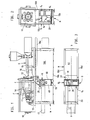
- the stationary mold carrier 12 of the mold clamping unit F is arranged approximately in the middle of the machine foot above its transverse wall 18 which is perpendicular to the closing direction of the mold clamping unit F and which delimits a tank space 43 which receives the oil for the hydraulic circuit.
- the plasticizing cylinder 16 of the injection molding unit can be moved on horizontal columns 15, the movable mold carrier 11 of the mold clamping unit F on columns 14.
- the columns 14 are supported at one end on the stationary mold carrier 12 and at the other end on a mounting plate 19 which is arranged above the rear wall of the machine base and carries the hydraulic drive device 10 for the movable mold carrier 11.
- the cuboid machine base made of sheet steel is covered over the tank space 43 by a cover 18a and otherwise by the mold closing unit F.
- a device (separating device) for separating the sprues from the injection molds falling from the injection mold is arranged below the injection mold 13 in the machine base M. It is formed by a mechanical switch which comprises a horizontal pivot axis 35 and a plate 36 with sliding surfaces on both sides. The two extreme swivel positions of the plate form an angle of 90 °.
- the plate In one end position, the plate forms a slide for the falling molded parts, which ends on a conveyor belt 17, which is arranged symmetrically to the plane of symmetry bb of the injection molding machine and conveys it out of the back of the machine base.
- the plate 36 In the other pivoting position, the plate 36 forms a slide which ends above a comminution device for the sprues designed as a structural unit G.
- the comminution device comprises a cutting unit 28 operated with a drive motor 20, and a conveyor screw 27, 50 which conveys the sprues to the cutting unit, which is arranged transversely to the closing direction of the mold closing unit F and is driven by the drive motor 20 via a gear.
- the shredding device further comprises a container (regrind container 41) arranged under the cutting unit 28.
- the conveyor belt 17 is on the injection molding unit S facing away from the shredding device.
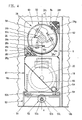
- Screw conveyor 27, 50 and cutting unit 28 have a common drive shaft (main shaft 26).
- the drive motor 20 is arranged parallel to and below the screw conveyor 27.
- Regenerate container 41 and drive motor 20 form the cuboid unit G.
- the width which is reduced in the closing direction of the mold closing unit F is determined by the diameter of the drive motor 20 or the conveyor screw formed by the conveyor helix 17 and the conveyor tube 50.
- Motor axis 20a and main shaft 26 lie in a common vertical plane aa. This plane aa is the plane of symmetry of the structural unit G.
- the cuboid unit G adjoins the transverse wall 18 of the machine base M delimiting the tank space 43.
- the broad side of the unit G facing the conveyor belt 17 for the molded parts is located approximately in a plane c-c passing through the parting plane c-c of the closed injection mold 13. In this plane lies approximately the horizontal pivot axis 35 of the separating device formed by the mechanical switch.
- the supporting skeleton of the structural unit G is formed by a horizontal base plate 51, a gear plate 29 receiving the gear shafts of a gear 24 and rigidly connected to the base plate 51, and the feed pipe 50 of the screw conveyor 27, 50 coaxial with the main shaft 26 and fastened to the gear plate 29 .
- the housing of the cutting unit 28 is thus formed by the free end section 50a of the conveyor tube 50 of the screw conveyor 27, 50.
- the gear plate 29 is supported on the motor side by stiffening brackets 29b in order to give it sufficient load-bearing capacity for the cutting unit 28.
- the countershaft 22 of the transmission 24 (with the rear cover plate 29a) transmitting the torque from the motor shaft 20a to the main shaft 26 lies in the plane of symmetry of the structural unit G.
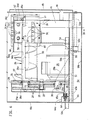
- the cutting unit 28 is axially delimited by two radial flanges enclosing the end section 50a of the delivery pipe 50. These are firmly connected to the jacket of the conveyor tube 50.
- the circumference of the flanges 60, 61 describes approximately a square.
- the cutting knives 28b of the cutting mechanism 28 are arranged on a cutting knife carrier 28a which is firmly seated on the main shaft 26. They rest on corresponding contact surfaces of the cutting knife carrier 28a, which are tangential to the main shaft 26. With these tangential contact surfaces, the cutting knives 28b are clamped by means of clamping screws 58 which are perpendicular to them.
- set screws 62 for the cutting knives 28b enable the cutting edges of the cutting knives 28b to be readjusted.
- the heads of the set screws 62 rest on the rear of the associated cutting knife 28b and are in threaded engagement with the cutting knife holder 28a. In the set position, they are secured by a screw nut which rests on a shoulder of the cutting knife carrier 28a parallel to the clamping screws 58.
- the cutting blades 28b cooperate with radial counter cutting edges 28c.
- Bearing pieces 28f for the counter cutting edges 28c are arranged between the radial flanges 60, 61.
- the counter cutting edges 28c can be clamped by means of clamping pieces 28g and clamping screws 56 with radial contact surfaces of the bearing pieces 28f, as can be seen in particular from FIG. 4.
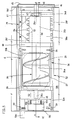
- the end section 50a of the conveyor tube 50 is closed off by means of a bearing flange 63 which receives the bearing of the main shaft. With an axial section of smaller diameter, the latter dips into this end section 50a.
- the main shaft 26 has an end section 26e facing the operating side of the plastic injection molding machine with a bearing 26d in the bearing flange 63, carries the cutting knife carrier 28a in a section 26b adjoining it on the rear, and the conveying coil 27 in a further section 26a adjoining it on the rear receives, wherein the rear end (accommodated in the bearing 25) 26c forms the output shaft of the transmission 24.
- the feed pipe 50 has in the entrance section a cutout 50b serving as an inlet opening for the plastic material to be reduced.
- the conveyor pipe 50 is provided with a discharge opening for the shredded plastic material. It extends between the diametrical counter cutting edges 28c over a central angle of 180 °.
- This cutout 50c is covered by a sieve 28e which has radial sieve holes 28e ⁇ .
- the screen 28e is clamped over radially bent edges by means of tangential clamping screws 57 and by means of the clamping pieces 28g to the bearing pieces 28f.
- the comminuted plastic material falling through the sieve 28e can be supplied via a guide plate 55 inclined to the vertical and a suction nozzle 54 passing through the rear wall of the regenerate container 41. This is connected via a coaxial intermediate piece 54b and a connecting piece 54a passing through the rear wall 18c of the machine base M to a suction pipe which removes the plastic material, the latter not being shown in the drawing.
- the structural unit G is thus divided into a drive part G1, a gear part G2, a conveying part G3 and a cutting part G4 and a container part G5.
- the structural unit G can be pulled out of the machine base M (with base 18b) transversely to the closing direction of the mold closing unit F by means of rollers 59 in the guide part 52A of a base 52 connected to the machine base M.
- rollers 59 are mounted on the long sides of the base plate 51.
- the structural unit G can be locked in the working position with the aid of a locking device 53.
- This locking device 53 comprises an eccentric 53c serving as a bolt, which is firmly seated on a shaft 53b of the base 52 lying in the plane of symmetry aa. By rotating the shaft 53b (by means of hexagon socket 53a), the eccentric 53c can be driven into a corresponding cutout 51a of the base plate in the locking position.
- the dimensions and the arrangement of the eccentric 53c is such that, in the locking position, it presses the base plate 51 upward for axially locking the unit G, that is to say against the roller guides of the guide part 52A.
- An electrical connection for the drive motor 20 is through the Insertion or extraction movement of the unit G can be produced or canceled.
- One contact part 64 of the connection is fastened to the rear wall 18c of the machine base M and the other contact part 65 to the base plate 51.
- An angle plate 64a screwed to the rear wall 18c is used to fasten the contact part 64
- a section of the operator-side wall 18d of the machine base M corresponding to the side view of the structural unit G can be locked with the aid of a door 45.
- a safety switch 46 arranged on the door 45 controls the circuit of the drive motor 20 by actuating the safety switch 46 when the door 45 is opened or closed and thereby separating or closing the circuit of the drive motor.
- the comminution device arranged in the structural unit G and the mechanical switch (pivot axis 35 and plate 36) can be controlled by the central computer of the plastic injection molding machine in such a way that useless moldings, which are recognized by this computer due to the faulty execution of a production parameter, go directly into the Shredding device can be directed.
- the regenerate container 41 placed under the cutting unit on the base plate 51 is designed as an extendable drawer with a handle. It can therefore also be emptied manually, in which case the guide plate 55 is expediently removed from the regrind container 41.
Landscapes
- Engineering & Computer Science (AREA)
- Food Science & Technology (AREA)
- Manufacturing & Machinery (AREA)
- Mechanical Engineering (AREA)
- Injection Moulding Of Plastics Or The Like (AREA)
- Processing And Handling Of Plastics And Other Materials For Molding In General (AREA)
- Moulds For Moulding Plastics Or The Like (AREA)
Applications Claiming Priority (2)
| Application Number | Priority Date | Filing Date | Title |
|---|---|---|---|
| DE3637612 | 1986-11-05 | ||
| DE19863637612 DE3637612A1 (de) | 1986-11-05 | 1986-11-05 | Kunststoff-spritzgiessmaschine mit eingebauter zerkleinerungseinrichtung fuer die anguesse |
Publications (2)
| Publication Number | Publication Date |
|---|---|
| EP0266584A2 true EP0266584A2 (fr) | 1988-05-11 |
| EP0266584A3 EP0266584A3 (fr) | 1989-08-09 |
Family
ID=6313180
Family Applications (1)
| Application Number | Title | Priority Date | Filing Date |
|---|---|---|---|
| EP87114896A Withdrawn EP0266584A3 (fr) | 1986-11-05 | 1987-10-13 | Machine à mouler par injection des matières plastiques avec dispositif à broyer incorporé pour les carottes |
Country Status (4)
| Country | Link |
|---|---|
| US (1) | US4883418A (fr) |
| EP (1) | EP0266584A3 (fr) |
| JP (1) | JPS63188015A (fr) |
| DE (1) | DE3637612A1 (fr) |
Cited By (4)
| Publication number | Priority date | Publication date | Assignee | Title |
|---|---|---|---|---|
| WO1998026873A1 (fr) * | 1996-12-19 | 1998-06-25 | Nuga Ag | Broyeur a lames pour le broyage de matiere plastique |
| US7021576B2 (en) | 2003-06-19 | 2006-04-04 | Nuga AG Kunststoffschneidemühlen | Blade mill for grinding plastic material |
| CN103770272A (zh) * | 2014-01-09 | 2014-05-07 | 苏州工业园区协利塑胶有限公司 | 应用于注塑零件生产的分料机构 |
| CN119141790A (zh) * | 2024-11-18 | 2024-12-17 | 海宇股份有限公司 | 一种防火鞋靴注塑机成型模具及其使用方法 |
Families Citing this family (10)
| Publication number | Priority date | Publication date | Assignee | Title |
|---|---|---|---|---|
| DE3831129A1 (de) * | 1988-09-13 | 1990-03-22 | Karl Hehl | Spritzgiessmaschine mit einrichtung zum absondern von nicht brauchbaren spritzteilen bzw. von angussteilen |
| US5090628A (en) * | 1990-02-06 | 1992-02-25 | Sierra Machinery, Inc. | Chip crusher |
| DE19961882A1 (de) * | 1999-12-20 | 2001-06-28 | Getecha Ges Fuer Tech Anlagen | Schneidmühle zur Zerkleinerung von Kunststoffen |
| FR2855436B1 (fr) * | 2003-05-26 | 2006-03-17 | Martiplast | Dispositif de triage pour machine industrielle |
| US7455083B2 (en) * | 2004-09-07 | 2008-11-25 | Gerald Schlaf | Accumulator for gaseous systems |
| CN101306569B (zh) * | 2007-05-16 | 2011-03-23 | 鸿富锦精密工业(深圳)有限公司 | 模具装置和射出成型方法 |
| JP6426651B2 (ja) * | 2016-04-14 | 2018-11-21 | ファナック株式会社 | 金型内にて組立作業を行う射出成形システム |
| WO2020180626A1 (fr) * | 2019-03-01 | 2020-09-10 | Canon Virginia, Inc. | Système de moulage par injection doté de transporteurs servant à insérer ou éjecter des moules |
| WO2020210255A1 (fr) * | 2019-04-11 | 2020-10-15 | Canon Virginia, Inc. | Système de moulage par injection doté de dispositifs transporteurs servant à insérer ou éjecter des moules |
| CN113524562B (zh) * | 2021-09-16 | 2021-12-03 | 佛山昱希汽车科技有限公司 | 一种汽车氛围灯光导体注塑装置 |
Family Cites Families (16)
| Publication number | Priority date | Publication date | Assignee | Title |
|---|---|---|---|---|
| DE1053291B (de) * | 1955-12-07 | 1959-03-19 | J F Bas & Cie S A | Schneidmuehle mit am Rotor und am Stator angeordneten Messern |
| US3407444A (en) * | 1966-05-19 | 1968-10-29 | Husky Mfg Tool Works Ltd | Injection molding machine with scrap grinder |
| US3418694A (en) * | 1966-09-30 | 1968-12-31 | Pennsalt Chemicals Corp | Apparatus scrap grinder and plastic injection molding machine |
| US3566444A (en) * | 1968-05-27 | 1971-03-02 | Husky Mfg Tool Works Ltd | Scrap grinder for injection-molding machine |
| US3570569A (en) * | 1969-05-05 | 1971-03-16 | Hobart Mfg Co | Food mixing machine |
| US3672803A (en) * | 1970-05-13 | 1972-06-27 | Husky Mfg Tool Works Ltd | Scrap grinder for injection-molding machine |
| US3776675A (en) * | 1970-09-18 | 1973-12-04 | Olivetti & Co Spa | Injection moulding press with means for separating scrap material from the molded articles |
| US3860182A (en) * | 1973-11-05 | 1975-01-14 | Cumberland Eng Co | Auger feed granulator |
| US4321027A (en) * | 1979-06-18 | 1982-03-23 | Leesona Corporation | Under the press granulator construction |
| CH658622A5 (de) * | 1981-11-20 | 1986-11-28 | Karl Hehl | Maschinenfuss einer kunststoff-spritzgiessmaschine. |
| DE3242169C2 (de) * | 1982-06-18 | 1984-07-19 | Karl 7298 Loßburg Hehl | Horizontale Formschließeinheit einer Kunststoff-Spritzgießmaschine mit Gießform-Wechselvorrichtung |
| FR2534180A1 (en) * | 1982-10-12 | 1984-04-13 | Clayton Cie | Screw-feed grinder for plastic recovered from moulding, especially intended for an injection press. |
| DD222505A1 (de) * | 1983-12-27 | 1985-05-22 | Plast Elastverarb Ingbetrieb | Schneidemuehle zum vermahlen von angussteilen |
| CH667254A5 (de) * | 1984-03-08 | 1988-09-30 | Karl Hehl | Foerdervorrichtung an kunststoff-spritzgiessmaschine zum austragen der spritzlinge. |
| FR2567420A1 (fr) * | 1984-07-11 | 1986-01-17 | Clayton Cie | Broyeur a alimentation par vis de hauteur reduite |
| US4737095A (en) * | 1986-05-21 | 1988-04-12 | Karl Hehl | Component changing apparatus serving a group of injection molding machines |
-
1986
- 1986-11-05 DE DE19863637612 patent/DE3637612A1/de not_active Withdrawn
-
1987
- 1987-10-13 EP EP87114896A patent/EP0266584A3/fr not_active Withdrawn
- 1987-11-02 JP JP62275928A patent/JPS63188015A/ja active Granted
-
1988
- 1988-10-03 US US07/252,124 patent/US4883418A/en not_active Expired - Fee Related
Cited By (5)
| Publication number | Priority date | Publication date | Assignee | Title |
|---|---|---|---|---|
| WO1998026873A1 (fr) * | 1996-12-19 | 1998-06-25 | Nuga Ag | Broyeur a lames pour le broyage de matiere plastique |
| US7021576B2 (en) | 2003-06-19 | 2006-04-04 | Nuga AG Kunststoffschneidemühlen | Blade mill for grinding plastic material |
| CN103770272A (zh) * | 2014-01-09 | 2014-05-07 | 苏州工业园区协利塑胶有限公司 | 应用于注塑零件生产的分料机构 |
| CN103770272B (zh) * | 2014-01-09 | 2016-02-03 | 苏州工业园区协利塑胶有限公司 | 应用于注塑零件生产的分料机构 |
| CN119141790A (zh) * | 2024-11-18 | 2024-12-17 | 海宇股份有限公司 | 一种防火鞋靴注塑机成型模具及其使用方法 |
Also Published As
| Publication number | Publication date |
|---|---|
| US4883418A (en) | 1989-11-28 |
| DE3637612A1 (de) | 1988-05-19 |
| JPS63188015A (ja) | 1988-08-03 |
| EP0266584A3 (fr) | 1989-08-09 |
| JPH0343047B2 (fr) | 1991-07-01 |
Similar Documents
| Publication | Publication Date | Title |
|---|---|---|
| EP2704838B1 (fr) | Dispositif de broyage par impact et de production de matériaux, en particulier de bois, en plusieurs fractions | |
| EP0266584A2 (fr) | Machine à mouler par injection des matières plastiques avec dispositif à broyer incorporé pour les carottes | |
| EP0632961B1 (fr) | Conche | |
| EP3689561B1 (fr) | Dispositif d'usinage d'objets plans | |
| DE2256524A1 (de) | Verfahren und vorrichtung zum zerkleinern von gut in kleine stuecke | |
| EP2556920A2 (fr) | Dispositif d'aiguisage de lames d'un lame-couronne pour un déchiqueteur à aubage | |
| DE2836847A1 (de) | Volumenarme mehrwellenschneckenmaschinenaustrittsvorrichtung mit siebwechselvorrichtung | |
| DE2516111C2 (de) | Zerkleinerungsvorrichtung, insbesondere zur Verarbeitung von Papier und Kunststoffmaterial | |
| DE2451785A1 (de) | Hobelmaschine | |
| DE4105473C1 (fr) | ||
| EP0917911B1 (fr) | Dispositif de tamisage | |
| DE4433473A1 (de) | Schneidmühle | |
| DE20301354U1 (de) | Zerkleinerungsvorrichtung | |
| EP1495685B1 (fr) | Dispositif de fabrication d'articles de tabac en forme de tige avec filtre, notamment des cigarettes | |
| DE10026825C2 (de) | Zerkleinerungsvorrichtung | |
| EP0359012B1 (fr) | Machine à mouler par injection des matières plastiques avec dispositif de triage pour séparer des pièces moulées inutilisables | |
| DE102019007192A1 (de) | Vorrichtung zum Zerkleinern von schüttfähigem Aufgabegut sowie Verfahren zum Öffnen einer solchen Vorrichtung | |
| DE69807553T2 (de) | Vorrichtung zum Herstellen keramischer Gegenstände | |
| DE3808675C2 (fr) | ||
| WO2022258171A1 (fr) | Appareil de transformation pour des denrées alimentaires | |
| EP0383226A1 (fr) | Presse à vis, notamment pour broyer des matériaux, tels que déchets organiques ou analogues | |
| DE20309648U1 (de) | Zerkleinerungsanlage | |
| EP0884105A1 (fr) | Dispositif d'alimentation, de support, de palier et de montage pour appareils de broyage | |
| EP0955098A1 (fr) | Appareil de désintégration d'objets | |
| DE3918729A1 (de) | Vorrichtung zur zerkleinerung von kunststoffteilen, insbesondere geschaeumten kunststoff, wie z. b. schaumstoff |
Legal Events
| Date | Code | Title | Description |
|---|---|---|---|
| PUAI | Public reference made under article 153(3) epc to a published international application that has entered the european phase |
Free format text: ORIGINAL CODE: 0009012 |
|
| AK | Designated contracting states |
Kind code of ref document: A2 Designated state(s): AT CH DE FR GB IT LI NL |
|
| PUAL | Search report despatched |
Free format text: ORIGINAL CODE: 0009013 |
|
| AK | Designated contracting states |
Kind code of ref document: A3 Designated state(s): AT CH DE FR GB IT LI NL |
|
| STAA | Information on the status of an ep patent application or granted ep patent |
Free format text: STATUS: THE APPLICATION HAS BEEN WITHDRAWN |
|
| 18W | Application withdrawn |
Withdrawal date: 19890830 |