EP0266630A2 - Dispositif pour aspirer des matières fibreuses - Google Patents
Dispositif pour aspirer des matières fibreuses Download PDFInfo
- Publication number
- EP0266630A2 EP0266630A2 EP87115390A EP87115390A EP0266630A2 EP 0266630 A2 EP0266630 A2 EP 0266630A2 EP 87115390 A EP87115390 A EP 87115390A EP 87115390 A EP87115390 A EP 87115390A EP 0266630 A2 EP0266630 A2 EP 0266630A2
- Authority
- EP
- European Patent Office
- Prior art keywords
- suction channel
- suction
- carriage
- movable connection
- longitudinal slot
- Prior art date
- Legal status (The legal status is an assumption and is not a legal conclusion. Google has not performed a legal analysis and makes no representation as to the accuracy of the status listed.)
- Granted
Links
Images
Classifications
-
- D—TEXTILES; PAPER
- D01—NATURAL OR MAN-MADE THREADS OR FIBRES; SPINNING
- D01G—PRELIMINARY TREATMENT OF FIBRES, e.g. FOR SPINNING
- D01G7/00—Breaking or opening fibre bales
- D01G7/06—Details of apparatus or machines
- D01G7/10—Arrangements for discharging fibres
Definitions
- the invention relates to a device for suctioning fiber material from a bale opener with a suction channel with a fixed connection opening and a movable connection opening, the movable connection opening being part of a longitudinal slot in the suction channel which can be closed with a cover band.
- the suction channel has a fixed connection opening for connection to the suction side of an air conveying device and a movable connection opening for the introduction of the fiber material into the suction channel.
- the movable connection opening into which a pipe leading from the fiber take-off area opens, is part of a continuous longitudinal slot in the suction channel, which can be closed with a flexible cover strip made of spring steel.
- the masking tape one end of which is attached to the suction channel and the other end of which is fastened to a movable winding roller, is held in the closed position by the negative pressure in the suction channel.
- the arrangement of the suction channel next to the rails of the bale opener requires additional space and also prevents another row of bales from being placed on this side of the road.
- the object of the present invention is to provide a device which enables the fiber material to be sucked off in a space-saving manner which does not impede the bale installation and is streamlined.
- suction channel is arranged in a plane above the bale and the cover tape attached to both ends of the longitudinal slot is held in the closed position by magnetic action.
- the longitudinal slot is preferably arranged on the underside of the suction channel.
- a sufficiently wide contact surface for the masking tape on the suction channel is created by flanges which are covered with magnetic tapes on the side facing the masking tape.
- the flanges also serve as a running surface for a carriage which is provided with deflection rollers for the cover band and is suspended from the flanges.
- a U-shaped deflection of the cover band is effected in that the deflection rollers are mounted in pairs in the carriage at a distance from one another.
- two mutually opposite movable connection openings are arranged between the pairs of deflecting rollers, into each of which a pipe opens.
- a trouble-free feeding of the fiber material into the suction channel is ensured in that the pipes lead into the movable connection openings inclined in the suction direction.
- the movable connection openings are arranged offset to one another.
- a box-shaped insert containing the movable connection openings is arranged in the carriage, which is directed to the longitudinal slot is open.
- the insert expediently protrudes into the suction channel.
- sealing strips are attached to the side walls of the insert which extend in the longitudinal direction of the suction channel and which bear against the inner wall of the suction channel.
- a cover arranged on the insert closes the suction channel on the side opposite the stationary connection opening. The closure is perfected in that a seal is attached to the periphery of the lid.
- an air baffle protrudes into the suction channel and extends in the suction direction.
- the carriage is enclosed in a housing that lies against the suction channel with sealing strips.
- the sealing strips are preferably formed from bristles arranged closely next to one another. The movement of the carriage along the suction channel takes place through the moving bale opener, the carriage being coupled to the machine frame of the bale opener via fork-like drivers.
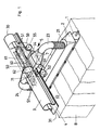
- FIG. 1 shows a take-off roller 1, which is covered with needles or teeth, of a bale opener which can be moved along a row of fiber bales B.
- the take-off roller 1 is covered by a suction hood 2 which has at least one suction opening.
- the second suction opening is not visible in Figure 1.
- the arrangement of two suction openings 21 at a distance from one another and in each case in the vicinity of the ends of the take-off roller 1 is particularly expedient if two or more fiber bales B arranged next to one another are to be processed simultaneously and the take-off roller 1 has a corresponding length.
- the take-off roller 1 can be moved together with the suction hood 2 in a manner not shown in the vertical direction. So that the pipes 23 and 24 can follow the vertical movement, they are at least partially designed as an expandable bellows.
- the suction channel 3 is arranged in a plane above the take-off roller 1, preferably approximately centrally above it. However, it can optionally also be arranged laterally from the take-off roller 1.
- the suction channel 3 has a tubular cross-section, the open side forming a longitudinal slot 31 of the Ab take roller 1 is facing. However, other designs of the suction channel and arrangements of the longitudinal slot are not excluded.
- the suction channel 3 has at one end a stationary connection opening 30 with which it is connected to the suction side of an air conveying device (not shown).
- the longitudinal slot 31 on the underside of the suction channel 3 is closed by a cover band 4, which consists of spring steel and is fastened to the suction channel 3 with a screw at both ends of the longitudinal slot 31 (not shown).
- the suction channel 3 is provided with outwardly directed flanges 32 against which the cover band 4 rests.
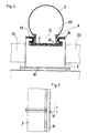
- the flanges 32 are each covered with a magnetic tape 33 on the side facing the cover tape 4 (FIG. 2), so that the cover tape 4 is held in the closed position by magnetic action on these contact surfaces.
- the top of the flange 32 serves as a tread for the wheels 51 of a carriage 5 which is suspended from the suction channel 3 by means of the wheels 51.
- Two pairs of deflecting rollers 52, 53 and 54, 55 are mounted in side walls 50 of the carriage 5 running parallel to the suction channel 3, through which the cover strip 4 is lifted from the longitudinal slot 31 and deflected.
- the deflecting roller pairs 52, 53, and 54, 55 are arranged at a distance from one another, the cover strip 4 running between two deflecting rollers and experiencing a U-shaped deflection away from the longitudinal slot 31.
- the box-shaped insert 6 preferably extends into the suction channel 3, elastic sealing strips 60 or sealing lips being fastened to the side walls extending in the longitudinal direction of the suction channel 3.
- the sealing strips 60 bear against the inner wall of the suction channel 3 (FIG. 3).
- a cover 62 closes the suction channel 3.
- the cover 62 is fastened to the insert 6 or integrated therein and can thus be moved with the carriage 5.
- the cover 62 has a seal 60 on its circumference.
- the expediently elastic seal 60 rubs against the inner wall of the suction channel 3 when the carriage 5 is displaced and thus simultaneously exerts a cleaning effect .
- Attached to the insert 6 or integrated therein is an air baffle 61, which enables the air loaded with fiber material to be guided into the suction channel 3 in a flow-favorable manner (FIGS. 1 and 2).
- This air baffle 61 extending into the suction channel 3 extends in the suction direction over the two deflection rollers 54 and 55 and covers the longitudinal slot 31 exposed between them.
- the car 5 with its insert 6 is completely enclosed in a housing 5 'which is firmly connected to the side walls 50 of the car 5 (FIG. 3).
- the housing 5 ' is shown in FIG. 4 on the open side facing the suction channel 3 all around with sealing strips 57, which suitably consist of closely spaced elastic bristles and rest on the cover tape 4 and on the flanges 32 and flanges 34.
- the flanges 34 can be provided with a pulse counting device 41 (FIG. 5) by means of which the travel distance of the bale opener is determined. The pulses are triggered by notches that are present on the flange 34 at equal intervals.
- the carriage 5 enclosed by the housing 5 ⁇ is driven by means of fork-like drivers 56 (FIG. 4) via which the carriage 5 or its housing 5 ⁇ is coupled to the machine frame of the bale opener.
Landscapes
- Engineering & Computer Science (AREA)
- Textile Engineering (AREA)
- Preliminary Treatment Of Fibers (AREA)
Applications Claiming Priority (2)
| Application Number | Priority Date | Filing Date | Title |
|---|---|---|---|
| DE3637580A DE3637580C1 (de) | 1986-11-04 | 1986-11-04 | Vorrichtung zum Absaugen von Fasermaterial |
| DE3637580 | 1986-11-04 |
Publications (3)
| Publication Number | Publication Date |
|---|---|
| EP0266630A2 true EP0266630A2 (fr) | 1988-05-11 |
| EP0266630A3 EP0266630A3 (en) | 1990-06-06 |
| EP0266630B1 EP0266630B1 (fr) | 1992-07-08 |
Family
ID=6313167
Family Applications (1)
| Application Number | Title | Priority Date | Filing Date |
|---|---|---|---|
| EP87115390A Expired - Lifetime EP0266630B1 (fr) | 1986-11-04 | 1987-10-21 | Dispositif pour aspirer des matières fibreuses |
Country Status (6)
| Country | Link |
|---|---|
| US (1) | US4813103A (fr) |
| EP (1) | EP0266630B1 (fr) |
| JP (1) | JPS63126921A (fr) |
| CN (1) | CN1009942B (fr) |
| BR (1) | BR8705605A (fr) |
| DE (2) | DE3637580C1 (fr) |
Cited By (2)
| Publication number | Priority date | Publication date | Assignee | Title |
|---|---|---|---|---|
| WO1990008847A1 (fr) * | 1989-02-03 | 1990-08-09 | Hergeth Hollingsworth Gmbh | Dispositif d'aspiration |
| GB2247029A (en) * | 1990-07-17 | 1992-02-19 | Hergeth Hubert A | Bale trimming |
Families Citing this family (6)
| Publication number | Priority date | Publication date | Assignee | Title |
|---|---|---|---|---|
| EP0386580A1 (fr) * | 1989-03-07 | 1990-09-12 | Maschinenfabrik Rieter Ag | Procédé et installation pour prélever des paquets de fibres à partir de balles |
| DE4131424C1 (fr) * | 1991-09-20 | 1993-01-14 | Hergeth Hollingsworth Gmbh, 4408 Duelmen, De | |
| DE102005059151B4 (de) | 2005-12-10 | 2017-10-19 | Hubert Hergeth | Schrägfräse |
| CH706899A1 (de) * | 2012-08-29 | 2014-03-14 | Rieter Ag Maschf | Abtragorgan zum Abtragen von Faserflocken von Faserballen. |
| DE102012108198B4 (de) * | 2012-09-04 | 2016-05-25 | Windmöller & Hölscher Kg | Vorrichtung zum Absaugen von Abfallprodukten einer Produktionsmaschine mit einem Absaugelement |
| CN107227513B (zh) * | 2015-03-06 | 2019-04-05 | 江苏五友棉业有限公司 | 圆盘抓棉机的吸罩吸力调节装置及其工作方法 |
Family Cites Families (4)
| Publication number | Priority date | Publication date | Assignee | Title |
|---|---|---|---|---|
| DE3206257C2 (de) * | 1982-02-20 | 1984-01-05 | Schubert & Salzer Maschinenfabrik Ag, 8070 Ingolstadt | Saugkanal für Textilmaschinen |
| US4507826A (en) * | 1982-10-13 | 1985-04-02 | Keller Alex J | Method and apparatus for opening fiber bales |
| DE3334222C2 (de) * | 1983-09-22 | 1991-05-08 | Hergeth Hollingsworth GmbH, 4408 Dülmen | Vorrichtung zum Abtragen von Faserballen mittels einer Öffnervorrichtung |
| DE3503523C2 (de) * | 1985-02-02 | 1995-05-18 | Hergeth Hubert | Absaugvorrichtung für Ballenfräsen |
-
1986
- 1986-11-04 DE DE3637580A patent/DE3637580C1/de not_active Expired
-
1987
- 1987-10-20 BR BR8705605A patent/BR8705605A/pt unknown
- 1987-10-21 DE DE8787115390T patent/DE3780252D1/de not_active Expired - Lifetime
- 1987-10-21 EP EP87115390A patent/EP0266630B1/fr not_active Expired - Lifetime
- 1987-10-30 JP JP62273662A patent/JPS63126921A/ja active Pending
- 1987-11-02 US US07/115,708 patent/US4813103A/en not_active Expired - Fee Related
- 1987-11-03 CN CN87107669A patent/CN1009942B/zh not_active Expired
Cited By (3)
| Publication number | Priority date | Publication date | Assignee | Title |
|---|---|---|---|---|
| WO1990008847A1 (fr) * | 1989-02-03 | 1990-08-09 | Hergeth Hollingsworth Gmbh | Dispositif d'aspiration |
| GB2247029A (en) * | 1990-07-17 | 1992-02-19 | Hergeth Hubert A | Bale trimming |
| GB2247029B (en) * | 1990-07-17 | 1994-10-05 | Hergeth Hubert A | Bale trimming |
Also Published As
| Publication number | Publication date |
|---|---|
| DE3780252D1 (de) | 1992-08-13 |
| JPS63126921A (ja) | 1988-05-30 |
| US4813103A (en) | 1989-03-21 |
| CN87107669A (zh) | 1988-06-22 |
| EP0266630A3 (en) | 1990-06-06 |
| BR8705605A (pt) | 1988-06-14 |
| EP0266630B1 (fr) | 1992-07-08 |
| DE3637580C1 (de) | 1988-03-17 |
| CN1009942B (zh) | 1990-10-10 |
Similar Documents
| Publication | Publication Date | Title |
|---|---|---|
| EP0266630B1 (fr) | Dispositif pour aspirer des matières fibreuses | |
| EP0266629A2 (fr) | Appareil pour effectuer l'ouverture automatique et le mélange de balles de fibres | |
| DE3206257C2 (de) | Saugkanal für Textilmaschinen | |
| EP0311823A2 (fr) | Appareil pour ouvrir les balles de fibres | |
| DE3503523C2 (de) | Absaugvorrichtung für Ballenfräsen | |
| EP0436081B1 (fr) | Dispositif de transport | |
| DE2705688B1 (de) | Vorrichtung zum Abstuetzen von Textilfaserballen | |
| DE3518013C2 (fr) | ||
| DE2645464C2 (de) | Einrichtung zum unmittelbaren Fördern von leichten Gegenständen in einer Rinne | |
| DE19850626A1 (de) | Führungsschiene für ein Linearlager | |
| DE538119C (de) | Schornsteinaufsatz | |
| DE3805522A1 (de) | Staubschutzrohr fuer einen lichtsender oder lichtempfaenger | |
| DE2344541B2 (de) | Luftabsaugvorrichtung für die Vlieszusammenfaßzone einer Karde | |
| DE4235080C2 (de) | Duschabtrennung | |
| DE20007231U1 (de) | Vorrichtung zum Längsumreifen eines Gegenstandes | |
| DE2733421B2 (de) | Absaugeinrichtung bei Karden zum Reinhalten des Wanderdeckels | |
| EP0140819B1 (fr) | Dispositif pour établir une connexion entre deux conduites pneumatiques d'aspiration | |
| DE2428919A1 (de) | Schiebefenster mit einer seitlich verschiebbaren fensterscheibe | |
| DE10140341A1 (de) | Vorrichtung zur Auswahl von Samenkörnern | |
| DE3544537C2 (fr) | ||
| DE2221393C3 (de) | Magnetbandgerät | |
| DE10026510A1 (de) | Werkzeugmaschine | |
| DE1003127C2 (de) | Schutzvorrichtung an der Umkehrstation fuer Foerderbaender | |
| DE3416429A1 (de) | Abdeckung fuer mindestens zwei zueinander parallele, im abstand voneinander gelegene fuehrungsbahnen von werkzeugmaschinen | |
| EP0942088A2 (fr) | Dispositif d'aspiration |
Legal Events
| Date | Code | Title | Description |
|---|---|---|---|
| PUAI | Public reference made under article 153(3) epc to a published international application that has entered the european phase |
Free format text: ORIGINAL CODE: 0009012 |
|
| AK | Designated contracting states |
Kind code of ref document: A2 Designated state(s): CH DE FR GB IT LI |
|
| PUAL | Search report despatched |
Free format text: ORIGINAL CODE: 0009013 |
|
| AK | Designated contracting states |
Kind code of ref document: A3 Designated state(s): CH DE FR GB IT LI |
|
| 17P | Request for examination filed |
Effective date: 19900714 |
|
| 17Q | First examination report despatched |
Effective date: 19911210 |
|
| GRAA | (expected) grant |
Free format text: ORIGINAL CODE: 0009210 |
|
| AK | Designated contracting states |
Kind code of ref document: B1 Designated state(s): CH DE FR GB IT LI |
|
| REF | Corresponds to: |
Ref document number: 3780252 Country of ref document: DE Date of ref document: 19920813 |
|
| ET | Fr: translation filed | ||
| ITF | It: translation for a ep patent filed | ||
| GBT | Gb: translation of ep patent filed (gb section 77(6)(a)/1977) | ||
| PGFP | Annual fee paid to national office [announced via postgrant information from national office to epo] |
Ref country code: FR Payment date: 19921109 Year of fee payment: 6 |
|
| PGFP | Annual fee paid to national office [announced via postgrant information from national office to epo] |
Ref country code: GB Payment date: 19921111 Year of fee payment: 6 |
|
| PGFP | Annual fee paid to national office [announced via postgrant information from national office to epo] |
Ref country code: DE Payment date: 19921121 Year of fee payment: 6 |
|
| PGFP | Annual fee paid to national office [announced via postgrant information from national office to epo] |
Ref country code: CH Payment date: 19921215 Year of fee payment: 6 |
|
| PLBE | No opposition filed within time limit |
Free format text: ORIGINAL CODE: 0009261 |
|
| STAA | Information on the status of an ep patent application or granted ep patent |
Free format text: STATUS: NO OPPOSITION FILED WITHIN TIME LIMIT |
|
| 26N | No opposition filed | ||
| PG25 | Lapsed in a contracting state [announced via postgrant information from national office to epo] |
Ref country code: GB Effective date: 19931021 |
|
| PG25 | Lapsed in a contracting state [announced via postgrant information from national office to epo] |
Ref country code: LI Effective date: 19931031 Ref country code: CH Effective date: 19931031 |
|
| GBPC | Gb: european patent ceased through non-payment of renewal fee |
Effective date: 19931021 |
|
| PG25 | Lapsed in a contracting state [announced via postgrant information from national office to epo] |
Ref country code: FR Effective date: 19940630 |
|
| REG | Reference to a national code |
Ref country code: CH Ref legal event code: PL |
|
| PG25 | Lapsed in a contracting state [announced via postgrant information from national office to epo] |
Ref country code: DE Effective date: 19940701 |
|
| REG | Reference to a national code |
Ref country code: FR Ref legal event code: ST |
|
| PG25 | Lapsed in a contracting state [announced via postgrant information from national office to epo] |
Ref country code: IT Free format text: LAPSE BECAUSE OF NON-PAYMENT OF DUE FEES;WARNING: LAPSES OF ITALIAN PATENTS WITH EFFECTIVE DATE BEFORE 2007 MAY HAVE OCCURRED AT ANY TIME BEFORE 2007. THE CORRECT EFFECTIVE DATE MAY BE DIFFERENT FROM THE ONE RECORDED. Effective date: 20051021 |