EP0266780B1 - Optischer Stecker mit einer polarisationserhaltenden Faser - Google Patents
Optischer Stecker mit einer polarisationserhaltenden Faser Download PDFInfo
- Publication number
- EP0266780B1 EP0266780B1 EP87116348A EP87116348A EP0266780B1 EP 0266780 B1 EP0266780 B1 EP 0266780B1 EP 87116348 A EP87116348 A EP 87116348A EP 87116348 A EP87116348 A EP 87116348A EP 0266780 B1 EP0266780 B1 EP 0266780B1
- Authority
- EP
- European Patent Office
- Prior art keywords
- fiber
- stress
- core
- polarization
- optical connector
- Prior art date
- Legal status (The legal status is an assumption and is not a legal conclusion. Google has not performed a legal analysis and makes no representation as to the accuracy of the status listed.)
- Expired - Lifetime
Links
- 239000013307 optical fiber Substances 0.000 title claims description 22
- 230000003287 optical effect Effects 0.000 title claims description 20
- 239000000835 fiber Substances 0.000 claims description 30
- 239000000853 adhesive Substances 0.000 claims description 16
- 230000001070 adhesive effect Effects 0.000 claims description 16
- VYPSYNLAJGMNEJ-UHFFFAOYSA-N Silicium dioxide Chemical compound O=[Si]=O VYPSYNLAJGMNEJ-UHFFFAOYSA-N 0.000 claims description 8
- 239000000377 silicon dioxide Substances 0.000 claims description 4
- 229910052681 coesite Inorganic materials 0.000 claims description 3
- 229910052906 cristobalite Inorganic materials 0.000 claims description 3
- 235000012239 silicon dioxide Nutrition 0.000 claims description 3
- 229910052682 stishovite Inorganic materials 0.000 claims description 3
- 229910052905 tridymite Inorganic materials 0.000 claims description 3
- 230000008602 contraction Effects 0.000 claims description 2
- 230000010287 polarization Effects 0.000 description 23
- 230000035882 stress Effects 0.000 description 16
- 230000008033 biological extinction Effects 0.000 description 8
- 230000006866 deterioration Effects 0.000 description 6
- 239000012790 adhesive layer Substances 0.000 description 2
- 239000012141 concentrate Substances 0.000 description 2
- 230000006355 external stress Effects 0.000 description 2
- 238000004519 manufacturing process Methods 0.000 description 2
- XUIMIQQOPSSXEZ-UHFFFAOYSA-N Silicon Chemical compound [Si] XUIMIQQOPSSXEZ-UHFFFAOYSA-N 0.000 description 1
- 239000000919 ceramic Substances 0.000 description 1
- 230000008878 coupling Effects 0.000 description 1
- 238000010168 coupling process Methods 0.000 description 1
- 238000005859 coupling reaction Methods 0.000 description 1
- 230000008030 elimination Effects 0.000 description 1
- 238000003379 elimination reaction Methods 0.000 description 1
- 239000011521 glass Substances 0.000 description 1
- 230000001678 irradiating effect Effects 0.000 description 1
- 239000000463 material Substances 0.000 description 1
- 238000004321 preservation Methods 0.000 description 1
- 230000001902 propagating effect Effects 0.000 description 1
- 229910052710 silicon Inorganic materials 0.000 description 1
- 239000010703 silicon Substances 0.000 description 1
- 239000000758 substrate Substances 0.000 description 1
Images

Classifications
-
- G—PHYSICS
- G02—OPTICS
- G02B—OPTICAL ELEMENTS, SYSTEMS OR APPARATUS
- G02B6/00—Light guides; Structural details of arrangements comprising light guides and other optical elements, e.g. couplings
- G02B6/24—Coupling light guides
- G02B6/42—Coupling light guides with opto-electronic elements
- G02B6/4201—Packages, e.g. shape, construction, internal or external details
- G02B6/4248—Feed-through connections for the hermetical passage of fibres through a package wall
-
- G—PHYSICS
- G02—OPTICS
- G02B—OPTICAL ELEMENTS, SYSTEMS OR APPARATUS
- G02B6/00—Light guides; Structural details of arrangements comprising light guides and other optical elements, e.g. couplings
- G02B6/24—Coupling light guides
- G02B6/36—Mechanical coupling means
- G02B6/38—Mechanical coupling means having fibre to fibre mating means
- G02B6/3807—Dismountable connectors, i.e. comprising plugs
- G02B6/381—Dismountable connectors, i.e. comprising plugs of the ferrule type, e.g. fibre ends embedded in ferrules, connecting a pair of fibres
- G02B6/3812—Dismountable connectors, i.e. comprising plugs of the ferrule type, e.g. fibre ends embedded in ferrules, connecting a pair of fibres having polarisation-maintaining light guides
-
- G—PHYSICS
- G02—OPTICS
- G02B—OPTICAL ELEMENTS, SYSTEMS OR APPARATUS
- G02B6/00—Light guides; Structural details of arrangements comprising light guides and other optical elements, e.g. couplings
- G02B6/24—Coupling light guides
- G02B6/36—Mechanical coupling means
- G02B6/38—Mechanical coupling means having fibre to fibre mating means
- G02B6/3807—Dismountable connectors, i.e. comprising plugs
- G02B6/3869—Mounting ferrules to connector body, i.e. plugs
-
- G—PHYSICS
- G02—OPTICS
- G02B—OPTICAL ELEMENTS, SYSTEMS OR APPARATUS
- G02B6/00—Light guides; Structural details of arrangements comprising light guides and other optical elements, e.g. couplings
- G02B6/24—Coupling light guides
- G02B6/36—Mechanical coupling means
- G02B6/38—Mechanical coupling means having fibre to fibre mating means
- G02B6/3807—Dismountable connectors, i.e. comprising plugs
- G02B6/3887—Anchoring optical cables to connector housings, e.g. strain relief features
-
- G—PHYSICS
- G02—OPTICS
- G02B—OPTICAL ELEMENTS, SYSTEMS OR APPARATUS
- G02B6/00—Light guides; Structural details of arrangements comprising light guides and other optical elements, e.g. couplings
- G02B6/24—Coupling light guides
- G02B6/36—Mechanical coupling means
- G02B6/38—Mechanical coupling means having fibre to fibre mating means
- G02B6/3807—Dismountable connectors, i.e. comprising plugs
- G02B6/389—Dismountable connectors, i.e. comprising plugs characterised by the method of fastening connecting plugs and sockets, e.g. screw- or nut-lock, snap-in, bayonet type
-
- G—PHYSICS
- G02—OPTICS
- G02B—OPTICAL ELEMENTS, SYSTEMS OR APPARATUS
- G02B6/00—Light guides; Structural details of arrangements comprising light guides and other optical elements, e.g. couplings
- G02B6/24—Coupling light guides
- G02B6/36—Mechanical coupling means
- G02B6/38—Mechanical coupling means having fibre to fibre mating means
- G02B6/3807—Dismountable connectors, i.e. comprising plugs
- G02B6/389—Dismountable connectors, i.e. comprising plugs characterised by the method of fastening connecting plugs and sockets, e.g. screw- or nut-lock, snap-in, bayonet type
- G02B6/3894—Screw-lock type
Definitions
- the present invention relates to an optical connector using a polarization-maintaining optical fiber according to the introduction portion of claim 1
- Such an optical connector is generally known for instance by the JP-A-56 161 512
- Optical fibers with high internal birefringence have been developed to maintain the polarization plane of the transmitted light over a long distance.
- the birefringence is caused by a stress anisotropy in the core.
- the stress anisotropy is achieved by doping material to have a larger thermal expansion coefficient than that of the silica substrate.
- the optical fiber described in the paper comprises a core and parts arranged around the core and applying stress to the core in a fixed direction.
- the optical fiber by making one of two orthogonal polarization planes of the light incident on the optical fiber coincident with the direction of the stress on the core (main stress direction), the polarization plane of the light propagating along the core is maintained in the direction of that stress.
- the polarization plane will rotate, causing deterioration of the polarization extinction ratio (power ratio of the two orthogonal polarizations). Therefore, utmost attention has to be paid to maintaining the polarization plane.
- a polarization-maintaining fiber having a polarization extinction ratio of over 40 dB, for instance, is used in a conventional optical connector, the polarization extinction ratio will deteriorate to somewhere between 15 and 40 dB, resulting in a fluctuation of the deterioration of the polarization extinction ratio from about 0 to 25 dB.
- An object of the present invention is to provide an optical connector whose polarization plane is free from rotation by the stresses resulting from the hardening of adhesive when a polarization-maintaining optical fiber is fixed with the adhesive to the inside of the ferrule of the optical connector.
- the present connector comprises a polarization-maintaining optical fiber for maintaining the polarization plane by applying stress in a prescribed axial direction perpendicular to the optical axis of the optical fiber.
- the fiber is inserted and fixed with adhesive into a ferrule, whose section perpendicular to the optical axis has an oval hole.
- the major axis of the oval hole coincides with the direction in which the stress is applied to the fiber, and the minor axis of the same is approximately equal to the diameter of the fiber.
- FIG. 1A shows a front view of the embodiment
- FIG. 1B is an enlarged section of FIG. 1A along line A-A.
- an oval hole 2 is opened in the direction of the central axis of a glass-made ferrule 1 for connecting a polarization-maintaining optical fiber 5.
- the minor axis 4 of the oval hole 2 is set equal to the diameter of the fiber 5 so that adhesive 8 can concentrate in the area along the major axis 3 of the oval hole 2.
- the fiber 5 comprises a core 6 and a clad having a pair of stress-applying parts 7 arranged in symmetrical positions with respect to the core 6.
- the stress-applying parts 7 are doped with 15 mol% of B2O3 to enlarge the coefficient of thermal expansion, and the core 6 and the clad surrounding it are primarily made of SiO2, whose coefficient of thermal expansion is smaller than that of the stress-applying parts 7. Therefore, during the production of the optical fiber 5, the thermally expanded stress-applying parts 7 contract when the optical fiber cools off, and pull the surrounding SiO2. As a result, the core 6 is pulled toward the stress-applying parts 7, and this pulling force turns into the stress applied to the core 6.
- the fiber 5 is so fixed in the oval hole 2 with the adhesive 8 that the line connecting the two stress-applying parts 7 of the fiber 5 substantially coincides with the major axis 3 of the hole 2.
- the adhesive 8, of an ultraviolet-hardened type is hardened by irradiating ultraviolet rays from outside the glass-made ferrule 1.
- the adhesive 8 concentrates in the area along the major axis 3, the direction of stress applied to the core 6 by the hardening and contraction of the adhesive 8 is substantially identical with that of the stress attributable to the stress-applying parts 7. As a result, there is no rotation of the polarization plane by the hardening of the adhesive 8, and a fluctuation of deterioration in the polarization extinction ratio is reduced to no more than 10 dB.
- an optical fiber of any other structure may as well be used only if stress is applied to its core in a monoaxial direction perpendicular to the central axis. It also should be noted that adhesive need not be an ultraviolet-hardened type.
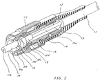
- FIG. 2 is a partially cut-out oblique view of an optical connector having the ferrule illustrated in FIGS. 1A and 1B.
- the direction of the tip of the ferrule is supposed to be forward, and the reverse direction, backward.
- a fiber cord 11 is inserted in the rear part of a rubber boot 12 and a cylindrical member 13 in the front part thereof.
- the rear part of the cylindrical member 13 fixes the fiber cord 11, and the front part of same is screwed into a housing 14.
- the housing 14 is arranged around a coated fiber 11a, resulting from the fiber cord 11 stripped of its external cover, and into its front part are inserted a spring 15 and the rear part of a ferrule 10.
- the ferrule 10 comprises first, second, third and fourth cylindrical parts 10a, 10b, 10c and 10d, each differing in diameter from others.
- the first cylindrical part 10a has an oval hole, in which is fixed a bare fiber 11b with adhesive.
- the bare fiber 11b results from the elimination of the silicon coat from the coated fiber 11a, and corresponds to the polarization-maintaining optical fiber of FIG. 1B. Therefore, its section perpendicular to the central axis of the first cylindrical part 10a is the same as what is shown in FIG. 1B.
- the coated fiber 11a is inserted and fixed within the second through fourth cylindrical parts 10b to 10d.
- Around the second cylindrical part 10b is arranged a flange 16a of the frame 16, and the flange 16a and the third cylindrical part 10c serve as stoppers to limit the shifting of the ferrule 10 in the direction of its central axis.
- a location key 18 is fixed partially on the external circumference of the front part of the frame 16.
- the location key 18 operates to position and prevent the rotation of the frame 16 when the optical connector is connected to an adapter.
- the key 18 is fixed in alignment with the direction of internal stress to represent the direction of the internal stress attributable to the stress-applying parts of the bare fiber 11b.
- a coupling nut 17 is arranged on the external circumference of the frame 16, and on its front part is formed a thread for fitting with an optical adaptor.
- the present invention makes it possible, when a polarization-maintaining optical fiber is fitted to an optical connector ferrule, to reduce the deterioration of the polarization extinction ratio and further to minimize its fluctuation.
Landscapes
- Physics & Mathematics (AREA)
- General Physics & Mathematics (AREA)
- Optics & Photonics (AREA)
- Mechanical Coupling Of Light Guides (AREA)
Claims (5)
- Optischer Stecker mit einer polarisationserhaltenden Lichtleitfaser (5, 11), welcher folgendes aufweist:- eine Zwingeneinrichtung (1, 10) mit einem Loch (2) zur Aufnahme der Lichtleitfaser (5, 11),dadurch gekennzeichnet,- daß das Loch (2) einen zur optischen Achse der Faser (5, 11) senkrechten und ovalen Querschnitt aufweist,- daß die Faser (5, 11) einen Kern (6) und Teile (7) zur mechanischen Belastung aufweist,- daß die Teile (7) zur mechanischen Belastung einen höheren Wärmeausdehnungskoeffizienten als der übrige Teil der Faser (5, 11) aufweisen und so angeordnet sind, daß sie den Kern in einer zur Mittelachse der Faser senkrechten einachsigen Richtung mechanisch belasten, und- daß Klebmittel (8) die Faser (5, 11) in dem ovalen Loch (2) fixieren, wodurch die größere Achse (3) des ovalen Lochs (2) mit der Richtung zusammenfällt, in der die Faser (5, 11) mechanisch belastet wird, während die kleinere Achse des Lochs in etwa gleich dem Durchmesser der Faser (5, 11) ist.
- Optischer Stecker nach Anspruch 1, bei welchem zwei langgestreckte Teile (7) zur mechanischen Belastung sich in Achsrichtung innerhalb der Faser (5, 11) symmetrisch auf gegenüberliegenden Seiten des Kerns erstrecken;
und bei welchem die größere Achse des ovalen Lochs (2) kolinear zu einer Linie verläuft, welche die innenliegenden Teile (7) zur mechanischen Belastung verbindet. - Optischer Stecker nach Anspruch 1, bei welchem die Faser (5, 11) und der Kern (6) in erster Linie aus SiO₂ bestehen, dessen Wärmeausdehnungskoeffizient kleiner ist als der der Teile (7) zur mechanischen Belastung, welche zur Erhöhung des Wärmeausdehnungskoeffizienten mit B₂O₃ dotiert sind.
- Optischer Stecker nach Anspruch 1, bei welchem die Richtung, in welcher der Kern (6) infolge Erhärtung und Volumenminderung des Klebstoffs (8) im wesentlichen identisch ist mit der Richtung der Belastung, die auf die Teile (7) zur mechanischen Belastung zurückzuführen ist.
- Optischer Stecker nach Anspruch 1, bei welchem der Klebstoff (8) sich in dem Bereich entlang der größeren Achse (3) des ovalen Lochs (2) konzentriert.
Applications Claiming Priority (2)
| Application Number | Priority Date | Filing Date | Title |
|---|---|---|---|
| JP262683/86 | 1986-11-06 | ||
| JP61262683A JPH0616126B2 (ja) | 1986-11-06 | 1986-11-06 | 光ファイバ接続用フェルール |
Publications (3)
| Publication Number | Publication Date |
|---|---|
| EP0266780A2 EP0266780A2 (de) | 1988-05-11 |
| EP0266780A3 EP0266780A3 (en) | 1990-02-14 |
| EP0266780B1 true EP0266780B1 (de) | 1994-02-02 |
Family
ID=17379139
Family Applications (1)
| Application Number | Title | Priority Date | Filing Date |
|---|---|---|---|
| EP87116348A Expired - Lifetime EP0266780B1 (de) | 1986-11-06 | 1987-11-05 | Optischer Stecker mit einer polarisationserhaltenden Faser |
Country Status (4)
| Country | Link |
|---|---|
| US (1) | US4907853A (de) |
| EP (1) | EP0266780B1 (de) |
| JP (1) | JPH0616126B2 (de) |
| DE (1) | DE3788998T2 (de) |
Families Citing this family (30)
| Publication number | Priority date | Publication date | Assignee | Title |
|---|---|---|---|---|
| US4812009A (en) * | 1987-06-30 | 1989-03-14 | American Telephone And Telegraph Company, At&T Bell Laboratories | Optical fiber connector |
| JPH0264508A (ja) * | 1988-08-31 | 1990-03-05 | Fujitsu Ltd | 定偏波光ファイバ固定用フェルール及び該フェルールを使用した定偏波光ファイバの固定方法 |
| JP2624328B2 (ja) * | 1989-05-19 | 1997-06-25 | 日本電気 株式会社 | 光合波分波器 |
| US5016970A (en) * | 1989-08-22 | 1991-05-21 | Nippon Telegraph And Telephone Corp. | Ferrule for optical fiber transmitting linearly polarized light and optical fiber connector using this ferrule |
| GB9007019D0 (en) * | 1990-03-29 | 1990-05-30 | British Telecomm | Optical fibre feedthrough |
| US5136433A (en) * | 1990-05-29 | 1992-08-04 | Durell William E | Optical positioner and connector |
| US5216733A (en) * | 1991-03-11 | 1993-06-01 | Nippon Telegraph And Telephone Corporation | Polarization maintaining optical fiber connector including positioning flange and method utilizing same |
| FR2678393B1 (fr) * | 1991-06-28 | 1995-02-10 | Cit Alcatel | Dispositif a fibre optique transversalement anisotrope et son procede de fabrication. |
| US5212753A (en) * | 1992-02-25 | 1993-05-18 | Hughes Aircraft Company | Polarization preserving fiber optic terminus |
| FR2725796B1 (fr) * | 1994-10-14 | 1997-01-03 | Alcatel Nv | Procede de fixation d'une fibre optique a maintien de polarisation et ferrule pour une telle fibre |
| JP2996602B2 (ja) * | 1995-01-31 | 2000-01-11 | 株式会社精工技研 | 定偏波光ファイバ用光分岐結合器 |
| US5682451A (en) * | 1995-05-23 | 1997-10-28 | Minnesota Mining And Manufacturing Company | Device with internal features for rotational alignment of non-cylindrically symmetrical optical elements |
| US5633970A (en) * | 1995-05-23 | 1997-05-27 | Minnesota Mining And Manufacturing Company | Device with internal asymmetrical features for rotational alignment of non-symmetrical articles |
| JP3294979B2 (ja) * | 1995-09-14 | 2002-06-24 | 株式会社精工技研 | 光ファイバの偏波面方向を指示する角度インデックスを備える光ファイバフェルール組立体 |
| JPH09171125A (ja) * | 1995-12-19 | 1997-06-30 | Emitsuto Seiko Kk | 光コネクタ |
| EP0784219A1 (de) * | 1996-01-10 | 1997-07-16 | R. Audemars Sa | Stift für optischen Stecker |
| JP2001272575A (ja) * | 2000-01-17 | 2001-10-05 | Seiko Instruments Inc | フェルール及び光コネクタ |
| FR2821933B1 (fr) * | 2001-03-07 | 2004-05-28 | Teem Photonics | Element de maintien et d'indexation d'une structure guidante asymetrique, et son utilisation pour la connexion de la structure a un composant d'optique integree |
| US6962445B2 (en) | 2003-09-08 | 2005-11-08 | Adc Telecommunications, Inc. | Ruggedized fiber optic connection |
| US7614797B2 (en) * | 2007-01-24 | 2009-11-10 | Adc Telecommunications, Inc. | Fiber optic connector mechanical interface converter |
| US7572065B2 (en) * | 2007-01-24 | 2009-08-11 | Adc Telecommunications, Inc. | Hardened fiber optic connector |
| US7591595B2 (en) * | 2007-01-24 | 2009-09-22 | Adc Telelcommunications, Inc. | Hardened fiber optic adapter |
| US7556437B2 (en) * | 2007-03-13 | 2009-07-07 | Adc Telecommunications, Inc. | Fiber optic connector with protective cap |
| US7722258B2 (en) * | 2007-05-06 | 2010-05-25 | Adc Telecommunications, Inc. | Interface converter for SC fiber optic connectors |
| WO2008137897A1 (en) * | 2007-05-06 | 2008-11-13 | Adc Telecommunications, Inc. | Mechanical interface converter for making non-ruggedized fiber optic connectors compatible with a ruggedized fiber optic adapter |
| US7744286B2 (en) | 2007-12-11 | 2010-06-29 | Adc Telecommunications, Inc. | Hardened fiber optic connection system with multiple configurations |
| US8123417B2 (en) * | 2009-06-01 | 2012-02-28 | Tyco Electronics Corporation | Optical connector with ferrule interference fit |
| GB0911359D0 (en) | 2009-06-30 | 2009-08-12 | Fibreco Ltd | Expanded beam optical fibre connection |
| US10444443B2 (en) | 2013-06-27 | 2019-10-15 | CommScope Connectivity Belgium BVBA | Fiber optic cable anchoring device for use with fiber optic connectors and methods of using the same |
| CN106796327B (zh) * | 2015-02-13 | 2021-03-16 | 古河电气工业株式会社 | 光纤的固定结构 |
Family Cites Families (11)
| Publication number | Priority date | Publication date | Assignee | Title |
|---|---|---|---|---|
| JPS5895704A (ja) * | 1981-12-03 | 1983-06-07 | Dai Ichi Seiko Co Ltd | 光コネクタ−用フエラル |
| JPS58223103A (ja) * | 1982-06-22 | 1983-12-24 | Hitachi Cable Ltd | 偏波面保存光フアイバ |
| JPS59174541A (ja) * | 1983-01-11 | 1984-10-03 | Hitachi Cable Ltd | 偏波面保存光フアイバ |
| US4529426A (en) * | 1983-07-22 | 1985-07-16 | At&T Bell Laboratories | Method of fabricating high birefringence fibers |
| US4673244A (en) * | 1984-04-24 | 1987-06-16 | Sachs/Freeman Associates, Inc. | Method of aligning a polarization-preserving optical fiber with a semiconductor laser for attachment of the fiber to the laser |
| JPS60254008A (ja) * | 1984-05-30 | 1985-12-14 | Nec Corp | 偏波面保存光フアイバ集合体整列用コネクタ |
| JPS60260010A (ja) * | 1984-06-06 | 1985-12-23 | Hitachi Cable Ltd | 偏波面保存光フアイバの接続方法 |
| JPS619608A (ja) * | 1984-06-25 | 1986-01-17 | Japan Aviation Electronics Ind Ltd | 偏波面保存光フアイバ |
| JPS60237406A (ja) * | 1985-04-19 | 1985-11-26 | Hitachi Ltd | 光フアイバ |
| US4762387A (en) * | 1986-02-21 | 1988-08-09 | American Telephone And Telegraph Company, At&T Bell Laboratories | Array connector for optical fibers |
| DE3625002C2 (de) * | 1986-07-24 | 1995-06-08 | Kabelmetal Electro Gmbh | Vorform für einen Monomode-Lichtwellenleiter |
-
1986
- 1986-11-06 JP JP61262683A patent/JPH0616126B2/ja not_active Expired - Lifetime
-
1987
- 1987-11-05 DE DE3788998T patent/DE3788998T2/de not_active Expired - Fee Related
- 1987-11-05 US US07/117,627 patent/US4907853A/en not_active Expired - Fee Related
- 1987-11-05 EP EP87116348A patent/EP0266780B1/de not_active Expired - Lifetime
Also Published As
| Publication number | Publication date |
|---|---|
| JPS63118107A (ja) | 1988-05-23 |
| EP0266780A2 (de) | 1988-05-11 |
| DE3788998D1 (de) | 1994-03-17 |
| EP0266780A3 (en) | 1990-02-14 |
| US4907853A (en) | 1990-03-13 |
| DE3788998T2 (de) | 1994-05-19 |
| JPH0616126B2 (ja) | 1994-03-02 |
Similar Documents
| Publication | Publication Date | Title |
|---|---|---|
| EP0266780B1 (de) | Optischer Stecker mit einer polarisationserhaltenden Faser | |
| US6705765B2 (en) | Polarization maintaining optical fiber connector plug | |
| CA1311381C (en) | Connector employing mode field modification | |
| US6744939B2 (en) | Polarization maintaining optical fiber connector and method of tuning (PM connector) | |
| EP1281995B1 (de) | Faseroptischer stecker | |
| US6619856B1 (en) | Polarization maintaining optical fiber connector adapter | |
| US6621946B2 (en) | Optical isolator | |
| JPH11505938A (ja) | 非対称物品を回転方向に心合せするための内部非対称特徴部を有する装置 | |
| US4919509A (en) | Mechanical connection for polarization-maintaining optical fiber and methods of making | |
| US5148508A (en) | Optical coupler housing | |
| US4607912A (en) | In-line optical fiber polarizer | |
| JP2000284149A (ja) | オフセットランチカップリングおよび光ファイバコネクタフェルール | |
| US12613379B2 (en) | Splice-on optical connectors for multicore fibers | |
| JPH0894879A (ja) | 偏波保持ファイバ用光コネクタ | |
| JP3517010B2 (ja) | 光コネクタ | |
| US20040247250A1 (en) | Integrated sleeve pluggable package | |
| JP7529053B2 (ja) | 円筒多心フェルール及び光コネクタ | |
| JPS63225207A (ja) | 偏波面保存光フアイバ−の端末固定方法 | |
| JPH07168067A (ja) | 光ファイバー | |
| JPS61186913A (ja) | 偏波面保存光フアイバコネクタ | |
| JP2946424B2 (ja) | 光アイソレータ付コネクタ | |
| WO2023175865A1 (ja) | 円筒多心フェルール及び光コネクタ | |
| JPH08184727A (ja) | 光コネクタ | |
| JPS58176612A (ja) | 単一偏波光フアイバの接続方法 | |
| JPH05113517A (ja) | 光導波路と光フアイバとの接続構造 |
Legal Events
| Date | Code | Title | Description |
|---|---|---|---|
| PUAI | Public reference made under article 153(3) epc to a published international application that has entered the european phase |
Free format text: ORIGINAL CODE: 0009012 |
|
| AK | Designated contracting states |
Kind code of ref document: A2 Designated state(s): DE FR GB |
|
| 17P | Request for examination filed |
Effective date: 19890707 |
|
| PUAL | Search report despatched |
Free format text: ORIGINAL CODE: 0009013 |
|
| AK | Designated contracting states |
Kind code of ref document: A3 Designated state(s): DE FR GB |
|
| 17Q | First examination report despatched |
Effective date: 19911212 |
|
| GRAA | (expected) grant |
Free format text: ORIGINAL CODE: 0009210 |
|
| AK | Designated contracting states |
Kind code of ref document: B1 Designated state(s): DE FR GB |
|
| PG25 | Lapsed in a contracting state [announced via postgrant information from national office to epo] |
Ref country code: FR Effective date: 19940202 |
|
| REF | Corresponds to: |
Ref document number: 3788998 Country of ref document: DE Date of ref document: 19940317 |
|
| EN | Fr: translation not filed | ||
| PLBE | No opposition filed within time limit |
Free format text: ORIGINAL CODE: 0009261 |
|
| STAA | Information on the status of an ep patent application or granted ep patent |
Free format text: STATUS: NO OPPOSITION FILED WITHIN TIME LIMIT |
|
| 26N | No opposition filed | ||
| PGFP | Annual fee paid to national office [announced via postgrant information from national office to epo] |
Ref country code: DE Payment date: 20001025 Year of fee payment: 14 |
|
| PGFP | Annual fee paid to national office [announced via postgrant information from national office to epo] |
Ref country code: GB Payment date: 20001101 Year of fee payment: 14 |
|
| PG25 | Lapsed in a contracting state [announced via postgrant information from national office to epo] |
Ref country code: GB Free format text: LAPSE BECAUSE OF NON-PAYMENT OF DUE FEES Effective date: 20011105 |
|
| REG | Reference to a national code |
Ref country code: GB Ref legal event code: IF02 |
|
| GBPC | Gb: european patent ceased through non-payment of renewal fee |
Effective date: 20011105 |
|
| PG25 | Lapsed in a contracting state [announced via postgrant information from national office to epo] |
Ref country code: DE Free format text: LAPSE BECAUSE OF NON-PAYMENT OF DUE FEES Effective date: 20020702 |