EP0266855B1 - Zwischenstecker für eine Kassette in einem Spielgerät - Google Patents
Zwischenstecker für eine Kassette in einem Spielgerät Download PDFInfo
- Publication number
- EP0266855B1 EP0266855B1 EP87302592A EP87302592A EP0266855B1 EP 0266855 B1 EP0266855 B1 EP 0266855B1 EP 87302592 A EP87302592 A EP 87302592A EP 87302592 A EP87302592 A EP 87302592A EP 0266855 B1 EP0266855 B1 EP 0266855B1
- Authority
- EP
- European Patent Office
- Prior art keywords
- cartridge
- adaptor
- gaming machine
- combination
- game
- Prior art date
- Legal status (The legal status is an assumption and is not a legal conclusion. Google has not performed a legal analysis and makes no representation as to the accuracy of the status listed.)
- Expired - Lifetime
Links
- 238000003780 insertion Methods 0.000 claims description 18
- 230000037431 insertion Effects 0.000 claims description 18
- 238000006243 chemical reaction Methods 0.000 claims description 4
- 230000000994 depressogenic effect Effects 0.000 description 7
- 230000001419 dependent effect Effects 0.000 description 2
- 238000010586 diagram Methods 0.000 description 2
- 238000004519 manufacturing process Methods 0.000 description 2
- 238000010276 construction Methods 0.000 description 1
- 230000002950 deficient Effects 0.000 description 1
- 238000000034 method Methods 0.000 description 1
- 239000011295 pitch Substances 0.000 description 1
- 230000004044 response Effects 0.000 description 1
Images


Classifications
-
- H—ELECTRICITY
- H05—ELECTRIC TECHNIQUES NOT OTHERWISE PROVIDED FOR
- H05K—PRINTED CIRCUITS; CASINGS OR CONSTRUCTIONAL DETAILS OF ELECTRIC APPARATUS; MANUFACTURE OF ASSEMBLAGES OF ELECTRICAL COMPONENTS
- H05K5/00—Casings, cabinets or drawers for electric apparatus
- H05K5/02—Details
- H05K5/0256—Details of interchangeable modules or receptacles therefor, e.g. cartridge mechanisms
Definitions
- the present invention relates to an adaptor for a cartridge for a gaming machine and particularly to an adaptor for fitting a cartridge for a gaming machine of a specified standard to a gaming machine of another standard.
- a processing apparatus such as a home television game or a personal computer (for example, a product known by the trade name MSX) uses a replaceable memory cartridge (or a replaceable cartridge) containing a memory (for example, a ROM or a battery-backed-up RAM) which stores a program of software such as a game, quiz or education program, so that a CPU incorporated in the processing apparatus executes desired processing to display a result (or a process) of the processing on a home television set.
- a replaceable memory cartridge or a replaceable cartridge
- a memory for example, a ROM or a battery-backed-up RAM
- Such cartridges and processing apparatuses are disclosed for example in Japanese Patent Laying-Open No. 2834/1979 and Japanese Patent Laying-Open No. 112352/1984.
- the processing apparatuses disclosed in these documents have an insertion opening in its upper surface for inserting a portion (a lower portion) of a cartridge and an edge connector is contained in a lower portion of the insertion opening.
- an edge connector is contained in a lower portion of the insertion opening.
- a system for loading a cartridge from a front face of a main body of a gaming machine In this system, an insertion opening for a cartridge is formed in a front face of a main body of a gaming machine and a front loading device 1 as shown in Fig. 12A is provided in an internal portion of the insertion opening.
- the front loading device 1 has a tray 2 for receiving a cartridge.
- the tray 2 is rotatably supported by a frame 3 and an edge connector 4 having a square shape in cross section is provided at an end of the tray 2.
- a circuit board of a cartridge 12 shown in Figs. 8A and 8B is inserted into the edge connector 4.
- a front loading system Such a system for loading a cartridge from a front face of a main body of a processing apparatus is hereinafter referred to as a front loading system.
- Home television gaming machines do not have any unified standard for memory cartridges and manufacturers utilize various cartridges.
- television gaming machines of the same company have different standards for cartridges dependent on the loading system.
- users want to use cartridges of a standard different from the standard conforming to home television gaming machines they possess they have to buy new home television gaming machines conforming to the different standard, which increases costs the users have to pay.
- such lack of interchangeability even among products of the same company, is also not desirable for makers or dealers because they cannot give good service to users and it is necessary too for makers to manufacture cartridges of various standards, causing the manufacturing cost to be high.
- an adaptor for a programmed cartridge for a video machine comprising a housing which is electrically and mechanically couplable in a first region to a programmed cartridge of a first type, said cartridge being directly couplable to a video machine of the first type, and which is electrically and mechanically couplable in a second region to a video machine of a second type with which the cartridge of the first type is not directly compatible, the adaptor having means electrically adapting the cartridge to the machine to enable the cartridge of the first type to be used with the machine of the second type.
- an embodiment of the present invention which is described hereinafter is an adaptor for adapting a cartridge for a first gaming machine to a second gaming machine.
- This adaptor contains a connection board and a connector in a case comprising an upper half and a lower half. At least a portion of the case is formed to have a shape adapted for the second gaming machine and a guide support means for the cartridge for the first gaming machine is formed in another portion of the case.
- the guide support means formed in the case serves as a guide for loading of the cartridge of the first gaming machine so as to precisely position the cartridge and the adaptor, and after the loading, the guide support means supports the cartridge to maintain the loading of the cartridge in a stable state.
- the present invention enables a cartridge of a certain gaming machine to be loaded reliably and stably into a gaming machine of another standard and thus interchangeability of cartridges can be attained.
- the guide support means guides and receives therein the cartridge when it is loaded into the gaming machine and consequently, positioning of a contact of the circuit board of the cartridge and a contact of the connector in the adaptor can be performed with precision.
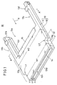
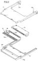
- FIG. 1 to 4 An embodiment of the present invention as shown in Figs. 1 to 4 is an adaptor for using, as a memory cartridge 30 of a front loading system shown in Figs. 8A and 8B, a memory cartridge 20 of a vertical loading system as shown in Fig. 7 containing a ROM or a RAM backed up by battery. Referring first to Figs. 1 to 4, construction of this embodiment will now be described.
- the adaptor 10 as shown in Figs. 1 to 4 comprises a case 13 formed by an upper half 11 and a lower half 12, a connection board 14 housed in this case 13, and a two-edge connector 15.
- the case 13 comprises a main body portion 13a and a guide support means 13b, 13c.
- the main body portion 13a occupies a nearly half area of the case 13 from a front edge 13d to the guide support means 13b, 13c.
- the guide support means 13b, 13c are formed by extensions of the two side portions of the main body portion 13a. Consequently, a receiving space 13e surrounded by the back end of the main body portion 13a and the inner side faces of the guide support means 13b, 13c is formed at the rear of the main body portion 13a.
- a cartridge 20 as shown in Fig. 7 is fitted in the receiving space 13e.
- the external shape and size of the case 13 are selected to be almost equal to an external shape and size of a cartridge 30 as shown in Figs. 8A and 8B.
- the main body portion 13a has L-shaped steps L1 and L2 on both sides thereof so that a width W1 near the front edge 13d of the case 13 is smaller than a width W2 in the other portion of the case 13.
- Those widths W1 and W2 are almost equal to a width W′1 and a width W′2, respectively, in the corresponding portions as shown in Fig. 8A.
- a distance dl from the front edge 13d to the respective ends of the steps L1 and L2 is almost equal to a distance d′1 in the corresponding portion as shown in Fig. 8A.
- a thickness t1 of the case 13 is almost equal to a thickness t′1 of the cartridge 30.
- tapers 13f, 13g are formed in both lower side portions of the lower half 12 of the case 13 in the same manner as in the cartridge 30 in which tapers 31a, 31b are formed in both lower side portions. The tapers 13f, 13g serve to prevent the adaptor 10 from being inserted in the main body of the gaming machine upside down.
- the main body of the gaming machine is constructed to receive the cartridge 30 only when the adaptor 10 is inserted with the faces having the tapers 13f, 13g being directed downward.
- An opening 13h is formed in the front edge 13d of the case 1 so that a part of an edge portion of the connection board 14 is accessible from the opening 13h.
- the back edge of the main body portion 13a and the inner side faces of the guide support means 13b, 13c which define the above stated receiving space 13e have a shape and a size substantially equal to the shape and the size of the cartridge 20.
- Tapers 13i, 13j are formed on both inner lower side faces of the lower half 12 in the guide support means 13b, 13c so as to fit to the tapers 21a, 21b formed on the two lower side faces of the case 21 of the cartridge 20. As a result, the cartridge 20 is prevented from being inserted upside down.
- projecting pieces 13k, 13l which project toward the receiving space 13e are formed on the respective upper surfaces of the guide support means 13b, 13c. Those projecting pieces 13k, 13l serve to guide a surface 21c of the cartridge 20 when it is inserted into the receiving space 13e and to maintain the fixed position of the surface 21c after insertion.
- the connection board 14 has a first connection terminal group 14a on an edge portion thereof and a second connection terminal group 14b on the other edge portion thereof.
- the shape, the positioning or pitches and the number of terminals of the first connection terminal group 14a are selected to be engaged with the main body of a gaming machine into which the adaptor 10 is inserted. More specifically, the number of terminals of the first group 14a is selected to be equal to the number of terminals formed on the circuit board 32 contained in the cartridge 30. On the other hand, the number of terminals of the second group 14b is selected to be equal to the number of terminals of the circuit board 22 contained in the cartridge 20.
- the two-edge connector 15 has insertion openings on both sides thereof so that two circuit boards inserted from the respective sides are electrically connected therein.
- One of the insertion openings of the two-edge connector 15 receives the above stated other edge portion of the connection board 14, namely, the other edge portion on which the second connection terminal group 14b are formed.
- the other insertion opening of the two-edge connector 15 receives the circuit board 22 of the cartridge 20 when the cartridge 20 is inserted.
- the shape and the size of the two-edge connector 15 are selected so that the two-edge connector 15 is received in the opening 21d formed at the front edge 21e of the cartridge 20.
- the two-edge connector 15 and the connection board 14 inserted into the connector 15 are placed on the lower half 12 and fixed thereto by screws (see Fig. 3). At this time, the two-edge connector 15 is disposed so that a part of the connector 15 projects backward from the lower half 12. Further, the upper half 11 is fixed on the lower half 12 so that assembling of the adaptor 10 is completed as shown in Fig
- the upper half 11 is fixed by screws in the main body portion 13a; however, the guide support means 13b, 13c do not have any space for screws and, therefore, fixing of the upper half 11 in the guide support means is effected in the following manner.
- the end portions of the guide support means 13b, 13c of the lower half 12 have projections protruding outwardly.
- the end portions of the guide support means 13b, 13c of the upper half 11 are L-shaped and bent downward. These L-shaped end portions have holes for receiving the above stated projections at positions opposed to the end portions of the lower half 12.
- the cartridge 20 is inserted into the adaptor 10 along the direction of the arrow X as shown in Fig. 1 with the front edge 21e of the cartridge 20 being introduced first.
- the side faces 21f, 21g of the cartridge 20 contact the inner side faces of the guide support means 13b, 13c, and the upper surface 21c contacts the lower surfaces of the projecting pieces 13k, 13l.
- the cartridge 20 is guided by the guide support means 13b, 13c and the projecting pieces 13k, 13l so that the cartridge 20 can be inserted into the adaptor 10 smoothly and correctly.
- the tapers 13i, 13j of the guide support means 13b, 13c respectively serve as obstacles to insertion of the cartridge 20 and, thus, the cartridge 20 can be prevented from being inserted upside down.
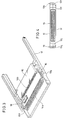
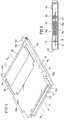
- Fig. 5 is a perspective view showing a state in which insertion of the cartridge 20 is completed.
- Fig. 6 is a sectional view taken along the line B-B as shown in Fig. 5.
- an edge portion of the two-edge connector 15 is received in the opening 21d of the cartridge 20 and a portion of the circuit board 22 is inserted into the two-edge connector 15.
- Upper contact terminals 15a and lower contact terminals 15b are provided on the two-edge connector 15 for the respective terminals of the circuit board 22.
- the respective two ends of the upper and lower contact terminals 15a, 15b are bent into a square shape so that the upper and lower contact terminals 15a, 15b have elasticity.
- the terminals of the circuit board 22 are held between the upper and lower contact terminals 15a, 15b so as to be stably in contact with the upper and lower contact terminals 15a, 15b.
- the elasticity of the upper and lower contact terminals 15a, 15b also serves to support the circuit board 22.
- the connection board 14 is also held between the upper and lower contact terminals 15a, 15b and, thus, a good contact state is obtained and the connection board 14 is supported by the upper and lower contact terminals 15a, 15b.
- a spacing member 15c is provided in a central portion of the two-edge connector 15 so as to provide a suitable space between the boards inserted from both sides.
- the cartridge 20 is supported by the two-edge connector 15, the inner side faces of the guide support means 13b, 13c and the lower surfaces of the projecting pieces 13k, 13l.
- the cartridge 20 inserted in the adaptor can be stably supported without any undesirable movement in the vertical direction.
- defective contact, damage or the like can be avoided.
- depressed portions 31c, 31d are formed on the upper and lower surfaces, respectively, of a case 31 of the cartridge 30. These depressed portions 31c, 31d are held by fingers when the cartridge 30 is taken out from the main body of the gaming machine.
- the depressed portion 31d formed on the lower surface also serves for mechanical determination as to a true or false state of the cartridge 30 dependent on the shape or the position of the depressed portion 31d. More specifically, a projection 6 of a prescribed height is formed in a prescribed position of the frame 3 of the front loading device (as shown in Figs. 12A and 12B) incorporated in the main body of the gaming machine and a hole 7 is provided in the tray 2 in a position opposed thereto.
- the projection 6 When the cartridge 30 is placed on the tray 2, the projection 6 is inserted into the depressed portion 31d through the hole 7. If a cartridge not containing the depressed portion 31d or a cartridge having a depressed portion at a different position or height is inserted into the main body of the gaming machine, the projection 6 obstructs insertion of the cartridge. Thus, only the cartridge 30 of the compatible standard can be inserted, whereby a true or false state is mechanically determined.
- the ends 13m, 13n of the guide support means 13b, 13c, respectively, of the adaptor 10 project beyond the end 21i of the cartridge 20 when the cartridge 20 is inserted into the adaptor 10. As a result, the loading of the adaptor 10 is not obstructed by the projection 6.
- the adaptor 10 to which the cartridge 20 is attached is inserted into the front loading device of the main body of the gaming machine along the direction of the arrow Y (as shown in Figs. 5 and 12A) with the front edge 13d thereof being inserted first. If the adaptor 10 is inserted with the back surface of the lower half 12 being directed upward, an elongate projection 8 in triangular section of the front loading device 1 obstructs the insertion of the adaptor 10 and thus reversed insertion of the adaptor 10 can be prevented.
- the tapers 21a, 21b are formed in the cartridge 20 and the tapers 13i, 13j are formed in the guide support means 13b, 13c so that the cartridge 20 can be prevented from being inserted in the adaptor 10 upside down.
- other means may be formed to prevent such reversed insertion.
- grooves 16a, 16b may be formed in the side faces of the cartridge 20 at positions a little away from the respective centers of the side faces, while projections 17a, 17b to be engaged with the grooves 16a, 16b, respectively, may be formed on the inner side faces of the guide support means 13b, 13c, respectively.
- the grooves 16a, 16b are not engaged with the projections 17a, 17b, respectively, and thus reversed insertion of the cartridge 20 is obstructed.
- Fig. 9 grooves 16a, 16b may be formed in the side faces of the cartridge 20 at positions a little away from the respective centers of the side faces, while projections 17a, 17b to be engaged with the grooves 16a, 16b, respectively, may be formed on the inner side faces of the guide support means 13b, 13c, respectively.
- grooves 16c, 16d having different widths may be formed in the side faces of the cartridge 20 and projections 17c, 17d to be engaged with the grooves 16c, 16d, respectively, may be formed on the inner side faces of the guide support means 13b, 13c, respectively.
- the grooves 16c, 16d are not engaged with the projections 17c, 17d, respectively, thereby preventing reversed insertion of the cartridge 20.
- grooves may be formed in the guide support means 13b, 13c and projections may be formed on the cartridge 20.
- Fig. 11 is a block diagram showing an example of a home television game system in which the embodiment as shown in Figs 1 to 6 is used.
- a program ROM 23 and a character ROM 24 are provided on the circuit board 22 of the cartridge 20.
- a program to be executed in the main body 40 of the gaming machine, namely, software for games and the like is stored in the program ROM 23.
- Information concerning various characters to be displayed on the home television receiver 50 is stored in the character ROM 24.
- output terminals of the program ROM 23 and the character ROM 24 are connected to the second connection terminal group 14b (as shown in Fig. 2) of the connection board 14 through the two-edge connector 15.
- a signal received by the terminals of the second connection terminal group 14b is subjected to address conversion in an integrated circuit element 18 and an output of the address conversion is supplied to the first connection terminal group 14a.
- the first connection terminal group 14a is connected to an edge connector 41.
- the edge connector 41 is connected with a CPU 42, a PPU (picture processing unit) 43 and an oscillator 44.
- the CPU 42 controls operation of the internal circuits of the main body 40 of the gaming machine.
- the PPU 43 performs processing for picture display based on the information supplied from the CPU 42, and an output of the PPU 43 is supplied to the television receiver 50 through an RF modulator 45.
- the CPU 42 is connected with an I/O interface 46 for connection with external apparatuses.
- game controllers 47a, 47b are connected as external apparatuses. Accordingly, in this case, the CPU 42 controls the progression of a game in response to instructions provided from the game controllers 47a and 47b.
- a lock circuit for preventing the starting of a game on a non-compatible cartridge is provided in the main body 40 of the gaming machine, and a program for cancelling the locking is stored in the integrated circuit element 18 of the adaptor 10.
- the present invention may be formed as an adaptor for attaining interchangeability from a cartridge of the front loading system to a cartridge of the vertical loading system, or interchangeability between cartridges of the vertical loading system or cartridges of the horizontal loading system. If cartridges of the vertical loading system are interchanged, a portion of a cartridge is inserted into the main body of the gaming machine and accordingly an adaptor in this case may be shaped so that at least the inserted portion may be engaged with the main body of the gaming machine.
Landscapes
- Engineering & Computer Science (AREA)
- Microelectronics & Electronic Packaging (AREA)
- Pinball Game Machines (AREA)
- Details Of Connecting Devices For Male And Female Coupling (AREA)
Claims (16)
- Kombination aus einem Spielgerät (40) mit einer Kassettenladeöffnung, in die eine Spielkassette von erstem, vorgegebenem Typ zum Spielen eines Spiels geladen werden kann, einer einsteckbaren Spielkassette (20) von zweitem, zum ersten unterschiedlichem Typ, und einem Zwischenstecker (10) mit einem in die Kassettenladeöffnung einsteckbaren ersten Teil (14a) und einem zweiten Teil (15), der die einsteckbare Spielkassette (20) vom zweiten Typ aufnimmt; dadurch gekennzeichnet, daß das Spielgerät eine Sperrschaltung zum Verhindern des Spielens eines Spiels mit einer Spielkassette nicht vom ersten, vorgegebenen Typ aufweist, und der Zwischenstekker (10) eine den ersten und zweiten Teil (14a, 15) verbindende Schaltung (14) aufweist, mit einer Einrichtung (18), die so ausgebildet ist, daß sie die Wirkung der Sperrschaltung aufhebt, so daß dann, wenn der Zwischenstecker (10) in die Kassettenladeöffnung des Spielgeräts (40) eingesteckt wird und die zweite, einsteckbare Spielkassette (20) im zweiten Teil (15) des Zwischensteckers (10) aufgenommen ist, das Spielen eines Spiels mit der zweiten, einsteckbaren Spielkassette (20) ermöglicht ist.
- Kombination nach Anspruch 1, bei der der Zwischenstekker (10) folgendes aufweist:- ein Gehäuse (13) mit einer oberen Hälfte (11) und einer unteren Hälfte (12), das so ausgebildet ist, daß es einen Bereich (13a) aufweist, von dem mindestens ein Teil so ausgebildet ist, daß er in das Spielgerät (40) paßt, und daß es an diesem Bereich (13a) gegenüberliegenden Positionen führende Halteeinrichtungen (13b, 13c) aufweist, um den zweiten Typ einer einsteckbaren Spielkassette (20) auf führende Weise in den Zwischenstecker (40) zu laden und die Kassette (40) zu halten, nachdem sie in diesen geladen wurde;- eine Leiterplatte (14) im Gehäuse (13), mit einer Kante, an der eine erste Gruppe (14a) von Verbindungsanschlüssen angeordnet ist, die so ausgebildet sind, daß sie eine Verbindung zum Spielgerät (40) herstellen, und mit einer anderen Kante, an der eine zweite Gruppe (14b) von Verbindungsanschlüssen angeordnet ist, die so ausgebildet sind, daß sie eine Verbindung zur einsteckbaren Spielkassette (20) vom zweiten Typ herstellen; und- einen Verbinder (15) zum elektrischen Verbinden der Gruppe (14b) von Verbindungsanschlüssen mit der Kassette (20), wenn diese in den Zwischenstecker (10) geladen ist, wobei mindestens ein Teil des Verbinders (15) im Gehäuse (13) untergebracht ist.
- Kombination nach Anspruch 2, bei der- die einsteckbare Spielkassette (20) vom zweiten Typ im wesentlichen Quaderform aufweist und- die führenden Halteeinrichtungen (13b, 13c) des Zwischensteckers (10) mit einer Form ausgebildet sind, die dergestalt ist, daß entgegengesetzte Seiten der Kassette (20) entlang der Richtung, in der sie in den Zwischenstecker geladen wird, geführt und gehalten werden.
- Kombination nach einem der Ansprüche 2 oder 3, bei der die führenden Halteeinrichtungen so ausgebildet sind, daß sie ein Laden der einsteckbaren Spielkassette (20) vom zweiten Typ in den Zwischenstecker (10) mit einer Ausrichtung verhindern, bei der die Oberseite nach unten zeigt.
- Kombination nach Anspruch 4, bei der die führenden Halteeinrichtungen (13b, 13c) Schrägen (13i, 13j) aufweisen, die an ihren Innenseiten ausgebildet sind, um mit ähnlichen Schrägen an der Kassette (20) zusammenzuwirken, um zu verhindern, daß die Kassette (20) mit der Oberseite nach unten geladen wird.
- Kombination nach Anspruch 4, bei der die führenden Halteeinrichtungen (13b, 13c) über Vorsprünge (17a bis 17d) verfügen, die an ihren Innenseiten ausgebildet sind, um mit Nuten (16a bis 16d) zusammenzuwirken, die an der Kassette (20) ausgebildet sind, um zu verhindern, daß die Kassette (20) mit der Oberseite nach unten geladen wird.
- Kombination nach Anspruch 4, bei der die führenden Halteeinrichtungen (13b, 13c) Gräben aufweisen, die an ihren Innenseiten ausgebildet sind, um mit an der Kassette (20) ausgebildeten Vorsprüngen zusmamenzuwirken, um zu verhindern, daß die Kassette (20) mit der Oberseite nach unten geladen wird.
- Kombination nach einem der Ansprüche 2 bis 7, bei der die führenden Halteeinrichtungen (13b, 13c) vorspringende Stücke (13k, 13l) aufweisen, um mindestens die Oberseite oder die Unterseite der Kassette (20) zu führen und zu halten.
- Kombination nach einem der Ansprüche 2 bis 8, bei der die führenden Halteeinrichtungen (13b, 13c) des Zwischensteckers (10) Endbereiche aufweisen, die so ausgebildet sind, daß die obere Hälfte (11) und die untere Hälfte (12) ineinander eingreifen.
- Kombination nach Anspruch 9, bei der die obere Hälfte (11) oder die untere Hälfte (12) des Gehäuses (13) über eine Umbiegung an den Enden der führenden Halteeinrichtungen (13b, 13c) verfügt, um dafür zu sorgen, daß die Endbereiche der oberen Hälfte (11) oder die Endbereiche der unteren Hälfte (12) jeweiligen Endbereichen der anderen Hälfte unter der oberen Hälfte (11) und der unteren Hälfte (12) gegenüberstehen, wobei ein Loch in der oberen Hälfte (11) oder der unteren Hälfte (12) in den gegenüberstehenden Endbereichen ausgebildet ist, und ein Vorsprung zum Eingriff in das Loch in der anderen Hälfte unter der unteren Hälfte (12) und der oberen Hälfte (11) ausgebildet ist, wobei ein Eingreifen des Vorsprungs in das Loch dazu führt, daß die obere Hälfte (11) und die untere Hälfte (12) ineinandergreifen.
- Kombination nach einem der Ansprüche 1 bis 10, bei der die Länge jeder der führenden Halteeinrichtungen (13b und 13c) so ausgewählt ist, daß dafür gesorgt ist, daß ihre Enden über das Ende (21i) der Kassette (20) überstehen, wenn die Kassette (20) in den Zwischenstecker (10) geladen ist.
- Kombination nach einem der Ansprüche 2 bis 11, bei der der Zwischenstecker (10) so ausgebildet ist, daß er ein Einführen dieses Bereichs (13a) mit der Oberseite nach unten in das Spielgerät (40) verhindert.
- Kombination nach Anspruch 12, bei der beide Seiten desjenigen Teils des Bereichs (13a), der so ausgebildet ist, daß er in das zweite Spielgerät paßt, Schrägen (13f, 13g) zum Zusammenwirken mit dem zweiten Spielgerät aufweisen, um zu verhindern, daß das Gehäuse (13) mit der Oberseite nach unten eingeführt werden kann.
- Kombination nach einem der Ansprüche 2 bis 13, bei der die Leiterplatte (14) eine Adressenumsetzeinrichtung (18) aufweist, um eine Adressenumsetzung zwischen Eingangs- und Ausgangssignalen der ersten Gruppe (14a) von Verbindungsanschlüssen sowie Eingangs- und Ausgangssignalen der zweiten Gruppe (14b) von Verbindungsanschlüssen auszuführen.
- Kombination nach einem der vorstehenden Ansprüche, bei der der Zwischenstecker (10) so ausgebildet ist, daß er es ermöglicht, daß eine Kassette für ein Spielgerät mit einem Vertikal- oder Horziontalladesystem bei einem Spielgerät für ein Horizontal- oder Vertikalladesystem verwendet werden kann.
- Kombination nach einem der Ansprüche 1 bis 14, bei der der Zwischenstecker (10) so ausgebildet ist, daß er es ermöglicht, daß eine Kassette für ein Spielgerät mit Vertikal- oder Horziontalladesystem bei einem Spielgerät mit einem Vertikal- oder Horizontalladesystem eines anderen Standards verwendet werden kann.
Applications Claiming Priority (2)
| Application Number | Priority Date | Filing Date | Title |
|---|---|---|---|
| JP61266079A JPH07100088B2 (ja) | 1986-11-07 | 1986-11-07 | ゲ−ム機用カ−トリツジのアダプタ |
| JP266079/86 | 1986-11-07 |
Publications (3)
| Publication Number | Publication Date |
|---|---|
| EP0266855A2 EP0266855A2 (de) | 1988-05-11 |
| EP0266855A3 EP0266855A3 (en) | 1989-08-09 |
| EP0266855B1 true EP0266855B1 (de) | 1995-09-27 |
Family
ID=17426054
Family Applications (1)
| Application Number | Title | Priority Date | Filing Date |
|---|---|---|---|
| EP87302592A Expired - Lifetime EP0266855B1 (de) | 1986-11-07 | 1987-03-25 | Zwischenstecker für eine Kassette in einem Spielgerät |
Country Status (5)
| Country | Link |
|---|---|
| US (1) | US4844465A (de) |
| EP (1) | EP0266855B1 (de) |
| JP (1) | JPH07100088B2 (de) |
| CA (1) | CA1278619C (de) |
| DE (1) | DE3751544T2 (de) |
Families Citing this family (23)
| Publication number | Priority date | Publication date | Assignee | Title |
|---|---|---|---|---|
| US5112051A (en) * | 1989-06-05 | 1992-05-12 | Westinghouse Electric Corp. | Interfacing device for a computer games system |
| GB8912866D0 (en) * | 1989-06-05 | 1989-07-26 | Code Masters Softwara | Interfacing device for a computer games system |
| GB2239810B (en) * | 1990-01-10 | 1994-06-22 | Leung Yiu Choi | Computer game control apparatus |
| US5155663A (en) * | 1990-02-19 | 1992-10-13 | Fuji Photo Film Co., Ltd. | Memory cartridge system with adapter |
| US5193052A (en) * | 1991-11-07 | 1993-03-09 | Advanced Matrix Technology, Inc. | Font cartridge extender with spring hook latch |
| GB9210786D0 (en) * | 1992-05-20 | 1992-07-08 | Codemasters Ltd | Memory cartridges |
| EP0571138A3 (de) * | 1992-05-20 | 1995-03-29 | Codemasters Ltd | Speicherkassette und Schnittstelle für Videospielkonsole. |
| USD340047S (en) | 1992-09-11 | 1993-10-05 | Tseng Ching J | Card-adapter for video game |
| JP3529394B2 (ja) * | 1992-10-19 | 2004-05-24 | 株式会社東芝 | Icカード情報処理装置 |
| CA2083017C (en) * | 1992-11-16 | 1999-02-09 | Alan Walter Ainsbury | Tandem circuit cards |
| US5282621A (en) * | 1992-11-24 | 1994-02-01 | Tseng Ching J | Universal converter for non-exclusive cards of video game |
| DE4303908A1 (de) * | 1993-02-10 | 1994-08-11 | Siemens Ag | Steuergerät |
| US5796940A (en) * | 1993-03-10 | 1998-08-18 | Sega Enterprises, Ltd. | Method for executing software program and circuit for implementing the method |
| JP3366413B2 (ja) * | 1993-07-27 | 2003-01-14 | 任天堂株式会社 | 表示情報変換装置および情報処理システム |
| JPH07211410A (ja) * | 1994-01-25 | 1995-08-11 | Nintendo Co Ltd | コネクタおよびそれを用いたアダプタ |
| US5889649A (en) * | 1994-03-01 | 1999-03-30 | Canon Kabushiki Kaisha | Information processing apparatus and a card-shaped adapter for smaller and larger storage medium |
| US5941775A (en) * | 1994-10-14 | 1999-08-24 | Sega Of America, Inc. | Data processing system, method thereof and memory cassette |
| US5856910A (en) * | 1996-10-30 | 1999-01-05 | Intel Corporation | Processor card assembly having a cover with flexible locking latches |
| US6102715A (en) | 1998-02-10 | 2000-08-15 | The Great American Gumball Corporation | Personal computer peripheral device adapter |
| JP3285321B2 (ja) * | 1998-02-26 | 2002-05-27 | 日本圧着端子製造株式会社 | カード接続用アダプタ |
| USD466130S1 (en) | 2002-02-08 | 2002-11-26 | Intec, Inc. | Video adaptor |
| US7634784B2 (en) * | 2004-04-08 | 2009-12-15 | Hewlett-Packard Development Company, L.P. | Data storage means |
| CN101639708B (zh) * | 2008-07-31 | 2012-05-30 | 鸿富锦精密工业(深圳)有限公司 | 触控系统以及移动通讯装置 |
Citations (1)
| Publication number | Priority date | Publication date | Assignee | Title |
|---|---|---|---|---|
| GB2115989A (en) * | 1982-02-12 | 1983-09-14 | Voltmace Limited | Programmed cartridge/video machine adaptor |
Family Cites Families (8)
| Publication number | Priority date | Publication date | Assignee | Title |
|---|---|---|---|---|
| US4114044A (en) * | 1977-05-09 | 1978-09-12 | Chiulli Robert D | Radiographic cassette adapter |
| US4149027A (en) * | 1977-05-27 | 1979-04-10 | Atari, Inc. | TV game cartridge and method |
| US4385264A (en) * | 1981-05-07 | 1983-05-24 | Rca Corporation | Start-up circuit for a power supply |
| DE3319141A1 (de) * | 1982-06-08 | 1983-12-08 | The Singer Co., 06904 Stamford, Conn. | Leiterplatten-steckmodul |
| US4596390A (en) * | 1983-01-19 | 1986-06-24 | Studley Fred M | Control cartridge selection device |
| US4480835A (en) * | 1983-03-02 | 1984-11-06 | Williams Theodore R | Cartridge adapter for programmable video games |
| US4531176A (en) * | 1983-06-27 | 1985-07-23 | At&T Bell Laboratories | Cartridge having improved electrostatic discharge protection |
| JPS60160089A (ja) * | 1984-01-30 | 1985-08-21 | Mitsubishi Plastics Ind Ltd | Icメモリ−カ−ド用接続カ−トリツジ |
-
1986
- 1986-11-07 JP JP61266079A patent/JPH07100088B2/ja not_active Expired - Lifetime
-
1987
- 1987-03-24 CA CA000532788A patent/CA1278619C/en not_active Expired - Fee Related
- 1987-03-25 EP EP87302592A patent/EP0266855B1/de not_active Expired - Lifetime
- 1987-03-25 DE DE3751544T patent/DE3751544T2/de not_active Expired - Lifetime
- 1987-04-17 US US07/039,300 patent/US4844465A/en not_active Expired - Lifetime
Patent Citations (1)
| Publication number | Priority date | Publication date | Assignee | Title |
|---|---|---|---|---|
| GB2115989A (en) * | 1982-02-12 | 1983-09-14 | Voltmace Limited | Programmed cartridge/video machine adaptor |
Also Published As
| Publication number | Publication date |
|---|---|
| JPH07100088B2 (ja) | 1995-11-01 |
| US4844465A (en) | 1989-07-04 |
| EP0266855A2 (de) | 1988-05-11 |
| EP0266855A3 (en) | 1989-08-09 |
| DE3751544T2 (de) | 1996-04-25 |
| CA1278619C (en) | 1991-01-02 |
| JPS63119789A (ja) | 1988-05-24 |
| DE3751544D1 (de) | 1995-11-02 |
Similar Documents
| Publication | Publication Date | Title |
|---|---|---|
| EP0266855A2 (de) | Zwischenstecker für eine Kassette in einem Spielgerät | |
| US5192082A (en) | TV game machine | |
| US5104333A (en) | Connector apparatus | |
| KR100625068B1 (ko) | 인쇄배선판용 커넥터 | |
| EP1073011B1 (de) | Pc-kartenrahmenbausatz, pc-karte und verfahren zu ihrer herstellung | |
| US5403207A (en) | Electrical connector with electrical component mounting structure | |
| EP0658956B1 (de) | Steckverbindersystem mit geringer Einsteckkraft | |
| US5622523A (en) | Grounding device for use with shielded DIN connector | |
| US5599232A (en) | Memory cartridge with interface having graphics co-processor | |
| US6628524B1 (en) | Frame kit for IC card and IC card using the same | |
| US5252089A (en) | Connector apparatus | |
| KR19990064126A (ko) | Ic카드후면기판지지체 | |
| JP3367417B2 (ja) | コネクタ | |
| JP2001284876A (ja) | 電子機器のシールドケース | |
| US6019631A (en) | Stacked electrical connector assembly | |
| KR101168883B1 (ko) | 단자위치 보장기구를 구비한 전기 커넥터 | |
| US4813885A (en) | Wiring harness connector retainer | |
| JP2001185288A (ja) | カード用コネクタ | |
| JPH0992415A (ja) | カードエッジコネクタ | |
| US4678256A (en) | Connector | |
| JP3357298B2 (ja) | イジェクト装置とそれを備えたカード用コネクタ | |
| JP3294193B2 (ja) | シールドコネクタ | |
| CN101114750B (zh) | 模块用连接器 | |
| US20030119342A1 (en) | Rotatably mated connector couple | |
| JP3428940B2 (ja) | カードコネクタ |
Legal Events
| Date | Code | Title | Description |
|---|---|---|---|
| PUAI | Public reference made under article 153(3) epc to a published international application that has entered the european phase |
Free format text: ORIGINAL CODE: 0009012 |
|
| AK | Designated contracting states |
Kind code of ref document: A2 Designated state(s): DE FR GB IT SE |
|
| PUAL | Search report despatched |
Free format text: ORIGINAL CODE: 0009013 |
|
| AK | Designated contracting states |
Kind code of ref document: A3 Designated state(s): DE FR GB IT SE |
|
| 17P | Request for examination filed |
Effective date: 19900205 |
|
| 17Q | First examination report despatched |
Effective date: 19920210 |
|
| GRAA | (expected) grant |
Free format text: ORIGINAL CODE: 0009210 |
|
| AK | Designated contracting states |
Kind code of ref document: B1 Designated state(s): DE FR GB IT SE |
|
| REF | Corresponds to: |
Ref document number: 3751544 Country of ref document: DE Date of ref document: 19951102 |
|
| ITF | It: translation for a ep patent filed | ||
| ET | Fr: translation filed | ||
| PLBE | No opposition filed within time limit |
Free format text: ORIGINAL CODE: 0009261 |
|
| STAA | Information on the status of an ep patent application or granted ep patent |
Free format text: STATUS: NO OPPOSITION FILED WITHIN TIME LIMIT |
|
| 26N | No opposition filed | ||
| REG | Reference to a national code |
Ref country code: GB Ref legal event code: IF02 |
|
| PGFP | Annual fee paid to national office [announced via postgrant information from national office to epo] |
Ref country code: FR Payment date: 20060308 Year of fee payment: 20 |
|
| PGFP | Annual fee paid to national office [announced via postgrant information from national office to epo] |
Ref country code: GB Payment date: 20060322 Year of fee payment: 20 |
|
| PGFP | Annual fee paid to national office [announced via postgrant information from national office to epo] |
Ref country code: DE Payment date: 20060323 Year of fee payment: 20 |
|
| PGFP | Annual fee paid to national office [announced via postgrant information from national office to epo] |
Ref country code: IT Payment date: 20060331 Year of fee payment: 20 |
|
| PG25 | Lapsed in a contracting state [announced via postgrant information from national office to epo] |
Ref country code: GB Free format text: LAPSE BECAUSE OF EXPIRATION OF PROTECTION Effective date: 20070324 |
|
| EUG | Se: european patent has lapsed | ||
| PGFP | Annual fee paid to national office [announced via postgrant information from national office to epo] |
Ref country code: SE Payment date: 20060306 Year of fee payment: 20 |