EP0266855A2 - Zwischenstecker für eine Kassette in einem Spielgerät - Google Patents
Zwischenstecker für eine Kassette in einem Spielgerät Download PDFInfo
- Publication number
- EP0266855A2 EP0266855A2 EP87302592A EP87302592A EP0266855A2 EP 0266855 A2 EP0266855 A2 EP 0266855A2 EP 87302592 A EP87302592 A EP 87302592A EP 87302592 A EP87302592 A EP 87302592A EP 0266855 A2 EP0266855 A2 EP 0266855A2
- Authority
- EP
- European Patent Office
- Prior art keywords
- cartridge
- gaming machine
- adaptor
- accordance
- guide support
- Prior art date
- Legal status (The legal status is an assumption and is not a legal conclusion. Google has not performed a legal analysis and makes no representation as to the accuracy of the status listed.)
- Granted
Links
Images


Classifications
-
- H—ELECTRICITY
- H05—ELECTRIC TECHNIQUES NOT OTHERWISE PROVIDED FOR
- H05K—PRINTED CIRCUITS; CASINGS OR CONSTRUCTIONAL DETAILS OF ELECTRIC APPARATUS; MANUFACTURE OF ASSEMBLAGES OF ELECTRICAL COMPONENTS
- H05K5/00—Casings, cabinets or drawers for electric apparatus
- H05K5/02—Details
- H05K5/0256—Details of interchangeable modules or receptacles therefor, e.g. cartridge mechanisms
Definitions
- the present invention relates to an adaptor of a cartridge for gaming machine and particularly to an adaptor for fitting a cartridge for a gaming machine of a specified standard to a gaming machine of another standard.
- a processing apparatus such as a home television game or a personal computer (for example, a product known by the trade name MSX) uses a replaceable memory cartridge (or a replaceable cartridge) containing a memory (for example, a ROM or a battery-backed-up RAM) which stores a program of software such as a game, quiz or education program, so that a CPU incorporated in the processing apparatus executes desired processing to display a result (or a process) of the processing on a home television set.
- a replaceable memory cartridge or a replaceable cartridge
- a memory for example, a ROM or a battery-backed-up RAM
- Such cartridges and processing apparatuses are disclosed for example in Japanese Patent Laying-Open No. 2834/1979 (counterpart United States Patent Application No. 801240 with the priority date May 27, 1977) and Japanese Patent Laying-Open No. 112352/1984 (counterpart United States Patent Application No.
- Any of the processing apparatuses disclosed in those documents has an insertion opening on its upper surface for inserting a portion (a lower portion) of a cartridge and an edge connector is contained in a lower portion of the insertion opening.
- a vertical loading system Such a system for loading a cartridge vertically into a main body of a processing apparatus is hereinafter referred to as a vertical loading system.
- the applicant of the present invention proposed, as the related art forming a background to the present invention, a system for loading a cartridge from a front face of a main body of a gaming machine and filed a patent application on this system as Japanese Patent Application No. 190372/1985 (counterpart United States Patent Application No. 900,717 filed August 27, 1986 and counterpart EPC Application No. 86,306,646).
- an insertion opening for cartridge is formed in a front face of a main body of a gaming machine and a front loading device 1 as shown in Fig. 12A is provided in an internal portion of the insertion opening.
- the front loading device 1 has a tray 2 for receiving a cartridge.
- the tray 2 is rotatably supported by a frame 3 and an edge connector 4 having a square shape in cross section is provided at an end of the tray 2.
- a circuit board of a cartridge 12 shown in Figs. 8A and 8B is inserted into the edge connector 4. After the cartridge 12 has been inserted, the tray 2 is moved downward and stopped in a horizontal state by a lock mechanism 5 so that the loading is completed.
- a front loading system Such a system for loading a cartridge from a front face of a main body of a processing apparatus is hereinafter referred to as a front loading system.
- Home television gaming machines do not have any unified standard for memory cartridges and manufacturers utilize various cartridges.
- television gaming machines of the same company have different standards for cartridges dependent on the loading system.
- users want to use cartridges of a standard different from the standard conforming to home television gaming machines they possess they have to buy new home television gaming machines conforming to the different standard, which increases costs the users have to pay.
- such lack of interchangeability even among products of the same company, is also not desirable for makers or dealers because they cannot give good service to users and it is necessary to for makers to manufacture cartridges of various standards, causing the manufacturing cost to be high.
- a primary object of the present invention is to provide an adaptor of a cartridge for gaming machine which assures interchangeability among cartridges for gaming machine of different types.
- Another object of the present invention is to provide an adaptor capable of loading, reliably and stably, a cartridge for a gaming machine of a specified type into a gaming machine of another type.
- the present invention is an adaptor for adapting a cartridge for a first gaming machine to a second gaming machine.
- This adaptor contains a connection board and a connector in a case comprising an upper half and a lower half. At least a portion of the case is formed to have a shape adapted for the second gaming machine and a guide support means for the cartridge for the first gaming machine is formed in another portion of the case.
- the guide support portion formed in the case serves as a guide for loading of the cartridge of the first gaming machine so as to precisely position the cartridge and the adaptor, and after the loading, the guide support portion supports the cartridge to maintain the loading of the cartridge in a stable state.
- a cartridge of a certain gaming machine can be loaded reliably and stably into a gaming machine of another standard and thus interchangeability of cartridges can be attained.
- the guide support means guides and receives therein the cartridge when it is loaded into the gaming machine and consequently, positioning of a contact of the circuit board of the cartridge and a contact of the connector in the adaptor can be performed with precision.
- An adaptor of an embodiment of the present invention shown in Figs. 1 to 4 is an adaptor for using, as a memory cartridge 30 of a front loading system shown in Figs. 8A and 8B, a memory cartridge 20 of a vertical loading system as shown in Fig. 7 containing a ROM or a RAM backed up by battery. Referring first to Figs. 1 to 4, construction of this embodiment will be described.
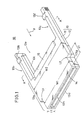
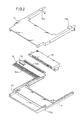
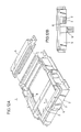
- the adaptor 10 of this embodiment shown in Figs. 1 to 4 comprises a case 13 formed by an upper half 11 and a lower half 12, a connection board 14 housed in this case 13, and a two-edge connector 15.
- the case 13 comprises a main body portion 13a and two guide support portions 13b and 13c.
- the main body portion 13a occupies a nearly half area of the case 13 from a front edge 13d to backward.
- the guide support portions 13b and 13c are formed by the two side portions of the main body portion 13a extending straight backward. Consequently, a receiving space 13e surrounded by the back end of the main body portion 13a and the inner side faces of the two guide support portions 13b and 13c is formed at the rear of the main body portion 13a.
- the external shape and the size of the case 13 are selected to be almost equal to an external shape and a size of a cartridge 30 shown in Figs. 8A and 8B. More specifically, in the same manner as in the cartridge 30, the main body portion 13a has L-shaped steps L1 and L2 on both sides thereof so that a width W1 near the front edge 13d is smaller than a width W2 in the other portion. Those widths W1 and W2 are almost equal to a width W ⁇ 1 and a width W ⁇ 2, respectively, in the corresponding portions shown in Fig. 8A.
- a distance dl from the front edge 13d to the respective ends of the steps L1 and L2 is almost equal to a distance d ⁇ 1 in the corresponding portion shown in Fig. 8A.
- a thickness t1 of the case 13 is almost equal to a thickness t ⁇ 1 of the cartridge 30.
- tapers 13f and 13g are formed in both lower side portions of the lower half 12 of the case 13 in the same manner as in the cartridge 30 in which tapers 31a and 31b are formed in both lower side portions. The tapers 13f and 13g serve to prevent the adaptor 10 from being inserted in the main body of the gaming machine upside down.
- the main body of the gaming machine is constructed to receive the cartridge 30 only when the adaptor 10 is inserted with the faces having the tapers 13f and 13g being directed downward.
- An opening 13h is formed in the front edge 13d of the case 1 so that a part of an edge portion of the connection board 14 is exposed from the opening 13h.
- the back edge of the main body portion 13a and the inner side faces of the guide support portions 13b and 13c which define the above stated receiving space 13e have a shape and a size substantially equal to the shape and the size of the cartridge 20.
- Tapers 13i and 13j are formed on both inner lower side faces of the lower half 12 in the guide support portions 13b and 13c so as to fit to the tapers 21a and 21b formed on the two lower side faces of the case 21 of the cartridge 20. As a result, the cartridge 20 is prevented from being inserted upside down.
- projecting pieces 13k and 13l which project toward the receiving space 13e are formed on the respective upper surfaces of the guide support portions 13b and 13c. Those projecting pieces 13k and 13l serve to guide a surface 21c of the cartridge 20 when it is inserted in the receiving space 13e and to maintain the fixed position of the surface 21c after the insertion.
- the connection board 14 has a first connection terminal group 14a in an edge portion thereof and a second connection terminal group 14b in the other edge portion thereof.
- the shape, the positioning or pitches and the number of terminals of the first connection terminal group 14a are selected to be fitted for the main body of a gaming machine into which the adaptor 10 is inserted. More specifically, the number of terminals of the first group 14a is selected to be equal to the number of terminals formed on the circuit board 32 contained in the cartridge 30. On the other hand, the number of terminals of the second group 14b is selected to be equal to the number of terminals of the circuit board 22 contained in the cartridge 20.
- the two-edge connector 15 has insertion openings for circuit board on both sides thereof so that two circuit boards inserted from the respective sides are electrically connected therein.
- One of the insertion openings of the two-edge connector 15 receives the above stated other edge portion of the connection board 14, namely, the other edge portion where the second connection terminal group 14b are formed.
- the other insertion opening of the two-edge connector 15 receives the circuit board 22 of the cartridge 20 when the cartridge 20 is inserted.
- the shape and the size of the two-edge connector 15 are selected so that the two-edge connector 15 is fitted in the opening 21d formed at the front edge 21e of the cartridge 20.
- the two-edge connector 15 and the connection board 14 inserted into the connector 15 are placed on the lower half 12 and fixed thereto by means of screws (see Fig. 3). At this time, the two-edge connector 15 is disposed so that a part of the connector 15 projects backward from the lower half 12. Further, the upper half 11 is fixed on the lower half 12 so that assembling of the adaptor 10 is completed as shown in Fig. 1.
- the cartridge 20 is inserted in the adaptor 10 along the direction of the arrow X shown in Fig. 1 with the front edge 21e of the cartridge 20 being introduced at first.
- the side faces 21f and 21g of the cartridge 20 contact the inner side faces of the guide support portions 13b and 13c, and the upper surface 21c contacts the lower surfaces of the projecting pieces 13k and 13l.
- the cartridge 20 is guided by the guide support portions 13b and 13c and the projecting pieces 13k and 13l so that the cartridge 20 can be inserted in the adaptor 10 smoothly and correctly.
- the tapers 13i and 13j of the guide support portions 13b and 13c respectively serve as obstacles to insertion of the cartridge 20 and, thus, the cartridge 20 can be prevented from being inserted upside down.
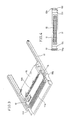
- Fig. 5 is a perspective view showing a state in which insertion of the cartridge 20 is completed.
- Fig. 6 is a sectional view taken along the line B-B shown in Fig. 5.
- an edge portion of the two-edge connector 15 is fitted in the opening 21d of the cartridge 20 and a portion of the circuit board 22 is inserted in the two-edge connector 15.
- Upper contact terminals 15a and lower contact terminals 15b are provided in the two-edge connector 15 for the respective terminals of the circuit board 22.
- the respective two ends of the upper and lower contact terminals 15a and 15b are bent in a square manner so that those upper and lower contact terminals 15a and 15b have elasticity.
- the terminals of the circuit board 22 are held between the upper and lower contact terminals 15a and 15b so as to be stably in contact with those upper and lower contact terminals 15a and 15b.
- the elasticity of the upper and lower contact terminals 15a and 15b also serves to support the circuit board 22.
- the connection board 14 is also held between the upper and lower contact terminals 15a and 15b and, thus, good contact state is obtained and the connection board 14 is supported by those upper and lower contact terminals 15a and 15b.
- a spacing member 15c is provided in a central portion of the two-edge connector 15 so as to provide a suitable space between the boards inserted from both sides.
- the cartridge 20 is supported by the two-edge connector 15, the inner side faces of the guide support portions 13b and 13c and the lower surfaces of the projecting pieces 13k and 13l.
- the cartridge 20 inserted in the adaptor can be stably supported without any undesirable shake in the vertical direction.
- defective contact, damage or the like can be avoided.
- depressed portions 31c and 31d are formed on the upper and lower surfaces, respectively, of a case 31 of the cartridge 30. Those depressed portions 31c and 31d serve as portions held by fingers when the cartridge 30 is taken out from the main body of the gaming machine.
- the depressed portion 31d formed on the lower surface also serves for mechanical determination as to a true or false state of the cartridge 30 dependent on the shape or the position of the depressed portion 31d. More specifically, a projection 6 of a prescribed height is formed in a prescribed position of the frame 3 of the front loading device (as shown in Figs. 12A and 12B) incorporated in the main body of the gaming machine and a hole 7 is provided in the tray 2 in a position opposed thereto.
- the projection 6 When the cartridge 30 is placed on the tray 2, the projection 6 is inserted in the depressed portion 31d through the hole 7. If a cartridge not containing the depressed portion 31d or a cartridge having a depressed portion at a different position or height is inserted into the main body of the gaming machine, the projection 6 obstructs insertion of the cartridge. Thus, only the cartridge 30 of the compatible standard can be inserted, whereby a true or false state is mechanically determined.
- the ends 13m and 13n of the guide support portions 13b and 13c, respectively, of the adaptor 10 project backward a little from the back end 21i of the cartridge 20 when the cartridge 20 is inserted in the adaptor 10. As a result, the loading of the adaptor 10 is not obstructed by the projection 6.
- the adaptor 10 to which the cartridge 20 is attached is inserted in the front loading device of the main body of the gaming machine along the direction of the arrow Y (as shown in Figs. 5 and 12A) with the front edge 13d thereof being inserted first. If the adaptor 10 is inserted with the back surface being directed upward, an elongate projection 8 in triangular section of the front loading device 1 obstructs the insertion of the adaptor 10 and thus reversed insertion of the adaptor 10 can be prevented.
- the tapers 21a and 21b are formed in the cartridge 20 and the tapers 13i and 13j are formed in the guide support portions 13b and 13c so that the cartridge 20 can be prevented from being inserted in the adaptor 10 upside down.
- other means may be formed to prevent such reversed insertion.
- grooves 16a and 16b may be formed in the side faces of the cartridge 20 at positions a little away from the respective centers of the side faces, while projections 17a and 17b to be engaged with the grooves 16a and 16b, respectively, may be formed on the inner side faces of the guide support portions 13b and 13c, respectively.
- the grooves 16a and 16b are not engaged with the projections 17a and 17b, respectively, and thus reversed insertion of the cartridge 20 is obstructed.
- grooves 16c and 16d having different widths may be formed in the side faces of the cartridge 20 and projections 17c and 17d to be engaged with the grooves 16c and 16d, respectively, may be formed on the inner side faces of the guide support portions 13b and 13c, respectively.
- the grooves 16c and 16d are not engaged with the projections 17c and 17d, respectively, thereby to prevent reversed insertion of the cartridge 20.
- grooves may be formed in the guide support portions 13b and 13c and projections may be formed on the cartridge 20.
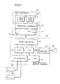
- Fig. 11 is a block diagram showing an example of a home television game system in which the embodiment shown in Figs. 1 to 6 is used.
- a program ROM 23 and a character ROM 24 are provided on the circuit board 22 of the cartridge 20.
- a program to be executed in the main body 40 of the gaming machine, namely, software for games and the like is stored in the program ROM 23.
- Information concerning various characters to be displayed on the home television receiver 50 is stored in the character ROM 24.
- output terminals of the program ROM 23 and the character ROM 24 are connected to the second connection terminal group 14b (as shown in Fig. 2) of the connection board 14 through the two-edge connector 15.
- a signal received by the terminals of the second connection terminal group 14b is subjected to address conversion in an integrated circuit element 18 and an output of the address conversion is supplied to the first connection terminal group 14a.
- the first connection terminal group 14a is connected to an edge connector 41.
- the edge connector 41 is connected with a CPU 42, a PPU (picture processing unit) 43 and an oscillator 44.
- the CPU 42 controls operation of the internal circuits of the main body 40 of the gaming machine.
- the PPU 43 performs processing for picture display based on the information supplied from the CPU 42, and an output of the PPU 43 is supplied to the television receiver 50 through an RF modulator 45.
- the CPU 42 is connected with an I/O interface 46 for connection with external apparatuses.
- game controllers 47a and 47b are connected as external apparatuses. Accordingly, in this case, the CPU 42 controls proceeding of a game in response to instructions provided from the game controllers 47a and 47b.
- a lock circuit for locking to stop a start of the game is provided in the main body 40 of the gaming machine, a program for cancelling the locking may be stored in the integrated circuit element 18 of the adaptor 10. In this case, the game is started only when the adaptor 10 of the compatible type is loaded in the main body 40 of the gaming machine and thus a false adaptor 10 can be excluded.
- the present invention may be formed as an adaptor for attaining interchangeability from a cartridge of the front loading system to a cartridge of the vertical loading system, or interchangeability between cartridges of the vertical loading system or cartridges of the horizontal loading system. If cartridges of the vertical loading system are interchanged, a portion of a cartridge is inserted in the main body of the gaming machine and accordingly an adaptor in this case may be shaped so that at least the inserted portion may be fitted for the main body of the gaming machine.
Landscapes
- Engineering & Computer Science (AREA)
- Microelectronics & Electronic Packaging (AREA)
- Pinball Game Machines (AREA)
- Details Of Connecting Devices For Male And Female Coupling (AREA)
Applications Claiming Priority (2)
| Application Number | Priority Date | Filing Date | Title |
|---|---|---|---|
| JP61266079A JPH07100088B2 (ja) | 1986-11-07 | 1986-11-07 | ゲ−ム機用カ−トリツジのアダプタ |
| JP266079/86 | 1986-11-07 |
Publications (3)
| Publication Number | Publication Date |
|---|---|
| EP0266855A2 true EP0266855A2 (de) | 1988-05-11 |
| EP0266855A3 EP0266855A3 (en) | 1989-08-09 |
| EP0266855B1 EP0266855B1 (de) | 1995-09-27 |
Family
ID=17426054
Family Applications (1)
| Application Number | Title | Priority Date | Filing Date |
|---|---|---|---|
| EP87302592A Expired - Lifetime EP0266855B1 (de) | 1986-11-07 | 1987-03-25 | Zwischenstecker für eine Kassette in einem Spielgerät |
Country Status (5)
| Country | Link |
|---|---|
| US (1) | US4844465A (de) |
| EP (1) | EP0266855B1 (de) |
| JP (1) | JPH07100088B2 (de) |
| CA (1) | CA1278619C (de) |
| DE (1) | DE3751544T2 (de) |
Cited By (4)
| Publication number | Priority date | Publication date | Assignee | Title |
|---|---|---|---|---|
| EP0602778A3 (de) * | 1992-11-16 | 1994-07-20 | International Business Machines Corporation | Kassette für auswechselbare oder tragbare Karte mit Schaltungen |
| DE4303908A1 (de) * | 1993-02-10 | 1994-08-11 | Siemens Ag | Steuergerät |
| EP0664580A3 (de) * | 1994-01-25 | 1995-10-18 | Nintendo Co Ltd | Verbinder und diesen Verbinder nutzenden Adapter. |
| EP0939582A3 (de) * | 1998-02-26 | 2000-01-12 | Japan Solderless Terminal Mfg. Co., Ltd. | Zwischensockel für Karte |
Families Citing this family (19)
| Publication number | Priority date | Publication date | Assignee | Title |
|---|---|---|---|---|
| US5112051A (en) * | 1989-06-05 | 1992-05-12 | Westinghouse Electric Corp. | Interfacing device for a computer games system |
| GB8912866D0 (en) * | 1989-06-05 | 1989-07-26 | Code Masters Softwara | Interfacing device for a computer games system |
| GB2239810B (en) * | 1990-01-10 | 1994-06-22 | Leung Yiu Choi | Computer game control apparatus |
| US5155663A (en) * | 1990-02-19 | 1992-10-13 | Fuji Photo Film Co., Ltd. | Memory cartridge system with adapter |
| US5193052A (en) * | 1991-11-07 | 1993-03-09 | Advanced Matrix Technology, Inc. | Font cartridge extender with spring hook latch |
| GB9210786D0 (en) * | 1992-05-20 | 1992-07-08 | Codemasters Ltd | Memory cartridges |
| EP0571138A3 (de) * | 1992-05-20 | 1995-03-29 | Codemasters Ltd | Speicherkassette und Schnittstelle für Videospielkonsole. |
| USD340047S (en) | 1992-09-11 | 1993-10-05 | Tseng Ching J | Card-adapter for video game |
| JP3529394B2 (ja) * | 1992-10-19 | 2004-05-24 | 株式会社東芝 | Icカード情報処理装置 |
| US5282621A (en) * | 1992-11-24 | 1994-02-01 | Tseng Ching J | Universal converter for non-exclusive cards of video game |
| US5796940A (en) * | 1993-03-10 | 1998-08-18 | Sega Enterprises, Ltd. | Method for executing software program and circuit for implementing the method |
| JP3366413B2 (ja) * | 1993-07-27 | 2003-01-14 | 任天堂株式会社 | 表示情報変換装置および情報処理システム |
| US5889649A (en) * | 1994-03-01 | 1999-03-30 | Canon Kabushiki Kaisha | Information processing apparatus and a card-shaped adapter for smaller and larger storage medium |
| US5941775A (en) * | 1994-10-14 | 1999-08-24 | Sega Of America, Inc. | Data processing system, method thereof and memory cassette |
| US5856910A (en) * | 1996-10-30 | 1999-01-05 | Intel Corporation | Processor card assembly having a cover with flexible locking latches |
| US6102715A (en) | 1998-02-10 | 2000-08-15 | The Great American Gumball Corporation | Personal computer peripheral device adapter |
| USD466130S1 (en) | 2002-02-08 | 2002-11-26 | Intec, Inc. | Video adaptor |
| US7634784B2 (en) * | 2004-04-08 | 2009-12-15 | Hewlett-Packard Development Company, L.P. | Data storage means |
| CN101639708B (zh) * | 2008-07-31 | 2012-05-30 | 鸿富锦精密工业(深圳)有限公司 | 触控系统以及移动通讯装置 |
Family Cites Families (9)
| Publication number | Priority date | Publication date | Assignee | Title |
|---|---|---|---|---|
| US4114044A (en) * | 1977-05-09 | 1978-09-12 | Chiulli Robert D | Radiographic cassette adapter |
| US4149027A (en) * | 1977-05-27 | 1979-04-10 | Atari, Inc. | TV game cartridge and method |
| US4385264A (en) * | 1981-05-07 | 1983-05-24 | Rca Corporation | Start-up circuit for a power supply |
| GB2115989B (en) * | 1982-02-12 | 1985-08-14 | Voltmace Limited | Programmed cartridge/video machine adaptor |
| DE3319141A1 (de) * | 1982-06-08 | 1983-12-08 | The Singer Co., 06904 Stamford, Conn. | Leiterplatten-steckmodul |
| US4596390A (en) * | 1983-01-19 | 1986-06-24 | Studley Fred M | Control cartridge selection device |
| US4480835A (en) * | 1983-03-02 | 1984-11-06 | Williams Theodore R | Cartridge adapter for programmable video games |
| US4531176A (en) * | 1983-06-27 | 1985-07-23 | At&T Bell Laboratories | Cartridge having improved electrostatic discharge protection |
| JPS60160089A (ja) * | 1984-01-30 | 1985-08-21 | Mitsubishi Plastics Ind Ltd | Icメモリ−カ−ド用接続カ−トリツジ |
-
1986
- 1986-11-07 JP JP61266079A patent/JPH07100088B2/ja not_active Expired - Lifetime
-
1987
- 1987-03-24 CA CA000532788A patent/CA1278619C/en not_active Expired - Fee Related
- 1987-03-25 EP EP87302592A patent/EP0266855B1/de not_active Expired - Lifetime
- 1987-03-25 DE DE3751544T patent/DE3751544T2/de not_active Expired - Lifetime
- 1987-04-17 US US07/039,300 patent/US4844465A/en not_active Expired - Lifetime
Cited By (6)
| Publication number | Priority date | Publication date | Assignee | Title |
|---|---|---|---|---|
| EP0602778A3 (de) * | 1992-11-16 | 1994-07-20 | International Business Machines Corporation | Kassette für auswechselbare oder tragbare Karte mit Schaltungen |
| CN1048565C (zh) * | 1992-11-16 | 2000-01-19 | 国际商业机器公司 | 扩展模块 |
| DE4303908A1 (de) * | 1993-02-10 | 1994-08-11 | Siemens Ag | Steuergerät |
| EP0664580A3 (de) * | 1994-01-25 | 1995-10-18 | Nintendo Co Ltd | Verbinder und diesen Verbinder nutzenden Adapter. |
| US5759104A (en) * | 1994-01-25 | 1998-06-02 | Nintendo Co., Ltd. | Connector and adapter utilizing connector |
| EP0939582A3 (de) * | 1998-02-26 | 2000-01-12 | Japan Solderless Terminal Mfg. Co., Ltd. | Zwischensockel für Karte |
Also Published As
| Publication number | Publication date |
|---|---|
| JPH07100088B2 (ja) | 1995-11-01 |
| US4844465A (en) | 1989-07-04 |
| EP0266855A3 (en) | 1989-08-09 |
| DE3751544T2 (de) | 1996-04-25 |
| EP0266855B1 (de) | 1995-09-27 |
| CA1278619C (en) | 1991-01-02 |
| JPS63119789A (ja) | 1988-05-24 |
| DE3751544D1 (de) | 1995-11-02 |
Similar Documents
| Publication | Publication Date | Title |
|---|---|---|
| EP0266855B1 (de) | Zwischenstecker für eine Kassette in einem Spielgerät | |
| US5192082A (en) | TV game machine | |
| US5403207A (en) | Electrical connector with electrical component mounting structure | |
| US4971563A (en) | Modular backplane assemblies for computers | |
| US5184961A (en) | Modular connector frame | |
| US5525071A (en) | Low connection force electrical connector system | |
| EP1073011B1 (de) | Pc-kartenrahmenbausatz, pc-karte und verfahren zu ihrer herstellung | |
| US6628524B1 (en) | Frame kit for IC card and IC card using the same | |
| KR19990064126A (ko) | Ic카드후면기판지지체 | |
| US5252089A (en) | Connector apparatus | |
| JP2000003416A (ja) | チップカード用接触アダプタ | |
| US4813885A (en) | Wiring harness connector retainer | |
| EP0251515B1 (de) | Scharnierartige elektrische Steckeranordnung | |
| JPH1022015A (ja) | プリント回路基板用コネクタ | |
| JP2001185288A (ja) | カード用コネクタ | |
| JPH11345652A (ja) | カードコネクタ | |
| US6629849B2 (en) | Rotatably mated connector couple | |
| JP3428940B2 (ja) | カードコネクタ | |
| JP3244615B2 (ja) | Pcカード | |
| JPH11135205A (ja) | カードコネクタ | |
| JPH0992370A (ja) | カードエッジコネクタ | |
| EP0476344B1 (de) | Fernsehspielmaschine | |
| JP2000208184A (ja) | コネクタ | |
| JPH09270280A (ja) | コネクタ付きユニットの装着構造 | |
| JPH0419678Y2 (de) |
Legal Events
| Date | Code | Title | Description |
|---|---|---|---|
| PUAI | Public reference made under article 153(3) epc to a published international application that has entered the european phase |
Free format text: ORIGINAL CODE: 0009012 |
|
| AK | Designated contracting states |
Kind code of ref document: A2 Designated state(s): DE FR GB IT SE |
|
| PUAL | Search report despatched |
Free format text: ORIGINAL CODE: 0009013 |
|
| AK | Designated contracting states |
Kind code of ref document: A3 Designated state(s): DE FR GB IT SE |
|
| 17P | Request for examination filed |
Effective date: 19900205 |
|
| 17Q | First examination report despatched |
Effective date: 19920210 |
|
| GRAA | (expected) grant |
Free format text: ORIGINAL CODE: 0009210 |
|
| AK | Designated contracting states |
Kind code of ref document: B1 Designated state(s): DE FR GB IT SE |
|
| REF | Corresponds to: |
Ref document number: 3751544 Country of ref document: DE Date of ref document: 19951102 |
|
| ITF | It: translation for a ep patent filed | ||
| ET | Fr: translation filed | ||
| PLBE | No opposition filed within time limit |
Free format text: ORIGINAL CODE: 0009261 |
|
| STAA | Information on the status of an ep patent application or granted ep patent |
Free format text: STATUS: NO OPPOSITION FILED WITHIN TIME LIMIT |
|
| 26N | No opposition filed | ||
| REG | Reference to a national code |
Ref country code: GB Ref legal event code: IF02 |
|
| PGFP | Annual fee paid to national office [announced via postgrant information from national office to epo] |
Ref country code: FR Payment date: 20060308 Year of fee payment: 20 |
|
| PGFP | Annual fee paid to national office [announced via postgrant information from national office to epo] |
Ref country code: GB Payment date: 20060322 Year of fee payment: 20 |
|
| PGFP | Annual fee paid to national office [announced via postgrant information from national office to epo] |
Ref country code: DE Payment date: 20060323 Year of fee payment: 20 |
|
| PGFP | Annual fee paid to national office [announced via postgrant information from national office to epo] |
Ref country code: IT Payment date: 20060331 Year of fee payment: 20 |
|
| PG25 | Lapsed in a contracting state [announced via postgrant information from national office to epo] |
Ref country code: GB Free format text: LAPSE BECAUSE OF EXPIRATION OF PROTECTION Effective date: 20070324 |
|
| EUG | Se: european patent has lapsed | ||
| PGFP | Annual fee paid to national office [announced via postgrant information from national office to epo] |
Ref country code: SE Payment date: 20060306 Year of fee payment: 20 |