EP0267516B1 - Méthode et appareil pour la fabrication des panneaux de fibres de bois - Google Patents
Méthode et appareil pour la fabrication des panneaux de fibres de bois Download PDFInfo
- Publication number
- EP0267516B1 EP0267516B1 EP87116121A EP87116121A EP0267516B1 EP 0267516 B1 EP0267516 B1 EP 0267516B1 EP 87116121 A EP87116121 A EP 87116121A EP 87116121 A EP87116121 A EP 87116121A EP 0267516 B1 EP0267516 B1 EP 0267516B1
- Authority
- EP
- European Patent Office
- Prior art keywords
- belt
- press
- hardener
- fleece
- acid
- Prior art date
- Legal status (The legal status is an assumption and is not a legal conclusion. Google has not performed a legal analysis and makes no representation as to the accuracy of the status listed.)
- Expired - Lifetime
Links
Images







Classifications
-
- B—PERFORMING OPERATIONS; TRANSPORTING
- B27—WORKING OR PRESERVING WOOD OR SIMILAR MATERIAL; NAILING OR STAPLING MACHINES IN GENERAL
- B27N—MANUFACTURE BY DRY PROCESSES OF ARTICLES, WITH OR WITHOUT ORGANIC BINDING AGENTS, MADE FROM PARTICLES OR FIBRES CONSISTING OF WOOD OR OTHER LIGNOCELLULOSIC OR LIKE ORGANIC MATERIAL
- B27N3/00—Manufacture of substantially flat articles, e.g. boards, from particles or fibres
- B27N3/08—Moulding or pressing
-
- B—PERFORMING OPERATIONS; TRANSPORTING
- B27—WORKING OR PRESERVING WOOD OR SIMILAR MATERIAL; NAILING OR STAPLING MACHINES IN GENERAL
- B27N—MANUFACTURE BY DRY PROCESSES OF ARTICLES, WITH OR WITHOUT ORGANIC BINDING AGENTS, MADE FROM PARTICLES OR FIBRES CONSISTING OF WOOD OR OTHER LIGNOCELLULOSIC OR LIKE ORGANIC MATERIAL
- B27N3/00—Manufacture of substantially flat articles, e.g. boards, from particles or fibres
- B27N3/08—Moulding or pressing
- B27N3/086—Presses with means for extracting or introducing gases or liquids in the mat
-
- B—PERFORMING OPERATIONS; TRANSPORTING
- B27—WORKING OR PRESERVING WOOD OR SIMILAR MATERIAL; NAILING OR STAPLING MACHINES IN GENERAL
- B27N—MANUFACTURE BY DRY PROCESSES OF ARTICLES, WITH OR WITHOUT ORGANIC BINDING AGENTS, MADE FROM PARTICLES OR FIBRES CONSISTING OF WOOD OR OTHER LIGNOCELLULOSIC OR LIKE ORGANIC MATERIAL
- B27N3/00—Manufacture of substantially flat articles, e.g. boards, from particles or fibres
- B27N3/08—Moulding or pressing
- B27N3/24—Moulding or pressing characterised by using continuously acting presses having endless belts or chains moved within the compression zone
-
- B—PERFORMING OPERATIONS; TRANSPORTING
- B30—PRESSES
- B30B—PRESSES IN GENERAL
- B30B5/00—Presses characterised by the use of pressing means other than those mentioned in the preceding groups
- B30B5/04—Presses characterised by the use of pressing means other than those mentioned in the preceding groups wherein the pressing means is in the form of an endless band
- B30B5/06—Presses characterised by the use of pressing means other than those mentioned in the preceding groups wherein the pressing means is in the form of an endless band co-operating with another endless band
- B30B5/065—Presses characterised by the use of pressing means other than those mentioned in the preceding groups wherein the pressing means is in the form of an endless band co-operating with another endless band using anti-friction means for the pressing band
-
- Y—GENERAL TAGGING OF NEW TECHNOLOGICAL DEVELOPMENTS; GENERAL TAGGING OF CROSS-SECTIONAL TECHNOLOGIES SPANNING OVER SEVERAL SECTIONS OF THE IPC; TECHNICAL SUBJECTS COVERED BY FORMER USPC CROSS-REFERENCE ART COLLECTIONS [XRACs] AND DIGESTS
- Y10—TECHNICAL SUBJECTS COVERED BY FORMER USPC
- Y10T—TECHNICAL SUBJECTS COVERED BY FORMER US CLASSIFICATION
- Y10T156/00—Adhesive bonding and miscellaneous chemical manufacture
- Y10T156/17—Surface bonding means and/or assemblymeans with work feeding or handling means
- Y10T156/1702—For plural parts or plural areas of single part
- Y10T156/1712—Indefinite or running length work
- Y10T156/1741—Progressive continuous bonding press [e.g., roll couples]
Definitions
- the invention relates to a method for producing wood-based panels according to the preamble of patent claim 1 and devices for carrying out this method according to the preamble of patent claims 26, 30 and 87.
- Such wood-based panels such as chipboard, fiber, OSB or MDF, consist of wood chips, wood fibers, etc., which are glued with a binder.
- the binders are usually urea, melamine or phenol-formaldehyde resins. These chips are then scattered into a fleece, which is compressed into a compact plate in a press. To accelerate the setting process, heat can be added during pressing and a hardener can be added to the binder solution before the chips are glued.
- Continuous processes are increasingly being used to produce such wood-based panels in which a continuous double belt press is used instead of the discontinuous deck press.
- the fleece is exposed to surface pressure and possibly heat during conveyance by the double belt press, so that the wood-based panel is produced as an endless web.
- DE-OS 34 11 590 also shows a system working with a double belt press for the production of wood-based panels by means of steam curing.
- distribution and collection channels are arranged on both sides of the press belts in the inlet area of the double belt press, from which nozzle holes extend to the press nip.
- the overheated water vapor is introduced from the distribution channels through the nozzle holes into the long sides of the fleece.
- DE-OS 34 14 178 shows a process which works with a discontinuous deck press and in which superheated steam is also fed to the fleece via the pressure plates.
- the system according to DE-OS 20 58 820 allows a more uniform vaporization over the width of the system and thus also a uniform curing across the width of the material plate, but the structure of the steam supply via the pressure plates and the press belts in the fleece is very expensive .
- the rollers run in this embodiment in a steam atmosphere in which there is a very high risk of corrosion for the rollers.
- the lubricant required for the rollers tends in a steam atmosphere usually to decomposition and thus leads to a scuffing of the rollers after a short operating time. Such presses have not proven to be reliable in the past and are therefore rarely used.
- EP-A-172 278 discloses a method for producing an article from organic material, in which the organic raw material is mixed with a binder. After the mixture is pressed into a predetermined shape, a hardener is fed to it.
- a disadvantage of this method is that the supply of the hardener, after the raw material has been pressed into a predetermined shape, requires a relatively long time to produce such molded parts.
- the invention has for its object to provide a method for the production of wood-based panels, which both greatly reduces the pressing time and reduces the heat input. In a continuous process using a double belt press, the use of shorter double belt presses should be possible.
- the advantages that can be achieved with the invention are, in particular, that no steam generation or a greatly reduced generation has to take place, so that the related energy costs are at least greatly reduced. Since the pressing time is shortened considerably compared to conventional continuous or discontinuous systems, the production performance of the system increases.
- the gas or steam atmosphere can be separated from the rollers, so that there is neither the risk of corrosive destruction of the rollers or other components of the double belt press nor the risk of the lubricant decomposing with a simultaneous impairment of its lubricity.
- the hardening of the wood-based panels can advantageously be controlled in a metered manner with the aid of the concentration of the acidic or basic gas.
- the method according to the invention can be carried out both with continuously operating plants for producing endless webs of wood-based panels and with discontinuous plants for producing wood-based panels with fixed dimensions.
- Continuous processes generally work with a double belt press, while discontinuous processes use single or multi-day presses.
- FIG. 1 Such a plant operating according to the method according to the invention for the continuous production of chipboard is shown in Figure 1.
- the wood chips are processed in devices arranged in front of the double belt press, pretreated and glued with hardener-free binder. Such devices are known per se and are therefore not shown in the drawing.
- These glued wood chips are fed to a forming station 3 via a pipeline 2.
- the forming station 3 is arranged above the end of a conveyor belt 6 on the right in the drawing, which is looped over two deflecting rollers 4 and 5 and moves continuously in the direction of the arrow towards the double belt press 1.
- the glued wood chips are scattered onto the conveyor belt to form a fleece consisting of a chip cake 7.
- the scattering can take place in such a way that a multi-layer chip cake is formed, for example a three-layer chip cake, in which the top layer consists of fine chips and the middle layer consists of coarse chips.
- the chip cake 7 is transported with the conveyor belt 6 in the direction of the arrow to the double belt press 1.
- further devices known per se and therefore not shown in the drawing can be arranged.
- Such devices can be, for example, checkweighers with which the basis weight of the chip cake is measured, pre-pressing devices, etc.
- a transfer plate 8 is arranged, which guides the chip cake 7 from the conveyor belt 6 into the entry zone of the double belt press 1.
- the chip cake 7 When entering the double belt press 1, the chip cake 7 is continuously compressed to the final thickness of the chipboard under the action of pressure.
- a hardener for the binder with which the wood chips are glued is in gaseous form or in a binary phase with a gaseous carrier within the double belt press 1 fed to the surfaces of the chip cake 7. This gas penetrates into the chip cake 7 via the surfaces, since this cake still has a low density during the compression phase.
- strong inorganic or organic acids act as particularly fast hardeners, which greatly accelerate the hardening reaction of the resin.
- Such acids are, for example, hydrochloric acid, sulfuric acid, phosphoric acid, formic acid, acetic acid, maleic acid and the like.
- inorganic bases act as fast hardeners.
- a basic hardener is, for example, ammonia.
- a cooling zone associated with the outlet can be present in the double belt press 1, so that the chipboard web is already cooled in the double belt press 1 under the effect of the surface pressure.
- the chipboard web 9 then leaves the double belt press 1 at a uniform speed and is further processed in the system parts following the double belt press 1. If necessary, the chipboard web 9 can then pass through a further cooling device, not shown in the drawing, for further cooling.
- the particle board web 9 is then ground to the finished size in a grinding station 10. Then the particle board web 9 is divided in a cross-cutting station 11 into individual particle boards 12 of the desired size, which are stacked in a stacking device 13 for removal on pallets.
- the entire process sequence in the plant shown in FIG. 1, The spreading of the chip cake 7 in the forming station 3, the specification and keeping constant of the process parameters of the double belt press 1 and the division of the chipboard web 9 into individual plates is controlled by a computer which is arranged in the control cabinet 14.
- the data terminal 15 serves to enter the parameters by the user.
- the computer in the control cabinet 14 can also be connected to an external host computer, which is located, for example, in the central EDP, in order to control the production and report back the production data enable further evaluation directly from the head office.
- the double belt press 1 for the continuous production of chipboard is shown schematically.
- the double belt press 1 has four guide drums 18, 19, 20, 21 rotatably mounted in bearing bridges 16, 17.
- Two press belts 22 and 23, each consisting of two press belts, are guided around two of these guide drums 18, 19, which closer is shown in Fig. 3.
- the direction of rotation of the press belt arrangement 22, 23 is indicated by arrows in the deflection drums 18 and 21.
- the chip cake 7 is passed between the press belt arrangements 22 and 23 through the double belt press 1.
- the chip cake 7 is first compressed in a wedge-shaped inlet zone 24, then through a medium-pressure reaction zone 25 with a constant gap width and then through a low-pressure mold holding zone 26, so that finally the chipboard web 9 on the deflection drums 19 and 20 leaves the double belt press 1.
- the pressure exerted in the individual zones 24, 25 and 26 via pressure plates 27, 28 and 29 can be selected depending on the requirements of the chip cake and the type of resin for glueing the chips.
- the reaction forces exerted by the chip cake 7 are transmitted via the pressure plates 27, 28, 29 and from support beams 30 connected to them into the press frame, which is only indicated schematically.
- the design of the press frame is known from DE-OS 32 34 082 and does not need here to be explained in more detail.
- the structure of the pressure plates 27, 28 can be seen in more detail in FIG. 3.
- the pressure plate 27 of the deflection drum 18 or 21 is too wedge-shaped and thus adapts to the shape of the wedge-shaped inlet zone 24.
- the pressure plate 28 for the medium pressure reaction zone 25 has a substantially rectangular cross section.
- a roller bed is arranged between the pressure plates 27, 28 and the inner belt 31 of the press belt arrangement 22 or 23 consisting of the inner belt 31 and outer belt 32, which transfers the pressure from the pressure plates 27, 28 to the press belt arrangement 22 or 23.
- the fixedly arranged in the double belt press 1 roller bed consists of staggered rollers 33, which are mounted on shafts 35 by means of bearing needles 34.
- the shafts 35 are fastened in bearing strips 36, which in turn are fastened on the side facing away from the inner belt 31 in the pressure plate 27 or 28 .
- the further training of such a roller bed can also be done according to DE-OS 31 23 291 or DE-OS 33 04 754.
- Transverse holes 37 are made in the pressure plates 27, 28, through which thermal oil can be passed if heating of the pressure plates 27, 28 is desired.
- a roller bed can also be attached between the pressure plate 29 and the inner band 31.
- a pressure chamber 38 can also be provided here (see FIG. 4). To the sides, this pressure chamber 38 is delimited by a sliding surface seal 39, which runs around the edge of the pressure chamber 38 without interruption.
- the sliding surface seal 39 is seated in a groove 40 in the pressure plate 29 and is acted upon from the groove base of the groove 40 with a pressure medium, which acts on an O-ring cord 41 lying against the sliding surface seal 39, so that the sliding surface seal slides firmly onto a surface the inner band 31 rests.
- a pressurizable fluid pressure medium is introduced, which exerts the pressing pressure on the press belt arrangement 22 or 23. Since there is generally no further compression of the chip cake 7 in the medium-pressure reaction zone 25, such a pressure chamber 38 can also be fitted there, if desired, instead of the roller bed between the pressure plate 28 and the inner belt 31.
- the inner band 31 and the outer band 32 of the press band arrangement 22 and 23 are spaced apart from one another. This distance is kept constant by spacers 42 which are fastened on the outer band 32 and extend across the width of the outer band 32. This creates a cavity between two spacers 42, which is formed by the spacers 42 and the outside of the inner band 31 and the inside of the outer band 32. This cavity extends over the width of the press belt arrangement 22 or 23 and thus forms a transverse channel 43.
- the spacer 42 can be seen in more detail in FIG. It consists of two strips 44 of L-shaped cross section, which are arranged such that the longer legs of the L are opposite one another and are at a distance from one another.
- the shorter legs of the L's are connected to the inside of the outer band 32 by a weld seam 48.
- a slide bar 45 is clamped into the groove formed by the distance between the two longer legs of the L-shaped bars 44. This slide bar 45 touches with its narrow surface in each case the inner band 31 and the outer band 32.
- the height of the slide bar 45 is chosen just as large as the desired distance between the inner and outer band.
- the slide bar 45 slides with its narrow surface on the outside of the inner band 31.
- the slide bar is made of a plastic with good sliding properties.
- polyimides are suitable.
- the slide bar there consists of a metal body 46, on the narrow surface of which the inner band 31 is assigned a slide surface 47 is applied.
- This sliding surface 47 consists of a dry sliding layer, for example of porous sintered tin bronze, the pores of which are filled with polytetrafluoroethylene or graphite. Due to the good metallic thermal conductivity of such dry sliding layers, such an embodiment is particularly suitable when heat transfer from the pressure plate to the inner band, from the inner band to the outer band and from the outer band to the chip cake is desired.
- additional lubrication of these surfaces can be provided.
- the L-shaped strips 44 can also be welded to the outside of the inner band 31 so that the slide bar 45 or 47 slides on the inside of the outer band 32.
- the spacers consist of a single molded part 49, which is connected to the inner band 31.
- This molded part 49 consists of a metal-rubber compound and is particularly suitable if no heat has to be supplied from the pressure plates 27, 28 via the press belt arrangement 22, 23 to the chip cake 7 for pressing the chip cake.
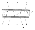
- the molded part 49 is fastened on the outside of the inner band 31 and has adjacent webs 50, the height of which is precisely the distance between the inner band 31 and outer band 32 corresponds. Between two webs 50, which run across the width of the press belt arrangement 22, 23, there is a transverse channel 51, which is too open to the inside of the outer belt 32.
- the webs 50 are connected to one another along the groove base of the channel 51 facing the inner band 31.
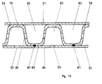
- a support band 78 is arranged between the inner band 31 and the outer band 32 of the press band arrangements 22, 23, which is deformed in a wave-like or approximately sinusoidal manner, so that adjacent elevations 79 and depressions 80, each with the same height, alternate.
- the support band 78 is loosely guided between the inner band 31 and outer band 32.
- it can also be attached to the outer band 32 either by means of spot welds 81 on the depressions 80, as shown in FIG. 10, or by means of spot welds on the elevations 79 (not shown in FIG. 10) on the inner band 31.
- transverse channels 82 and 83 are connected to one another with bores 84.
- an acidic or basic hardener for the binder with which the chips of the chip cake 7 are glued is in a gaseous phase or in a binary phase with a gaseous one Carrier supplied.
- a feed part 52 for the hardener is arranged on the left and right on the side of the double belt press 1 along the wedge-shaped inlet zone 24.
- This feed part 52 can be seen in section in FIG. 7.
- the feed part 52 can consist of two separate parts 52a and 52b for the upper one and the lower press belt arrangement 22, 23 consist, as shown on the left in FIG. 7, or of a single part 52, as can be seen on the right in FIG. 7.
- the one-piece feed part 52 has the advantage that the inlet zone 24 is laterally sealed.
- the feed part 52, 52a, 52b comprises the lateral edge region of the two press belt arrangements 22 and 23, which laterally protrude slightly beyond the rollers 33 of the roller bed.
- a recess 53 both in the area of the press belt arrangement 22 and of the press belt arrangement 23, the height of which is somewhat larger than the distance of the inner belt 31 from the outer belt 32 and the depth of which is somewhat larger than the protruding part of the press belt arrangement 22, 23.
- a sealing element 54 is attached, which touches the edges of the inner band 31 and the outer band 32 under light pressure, and covers the edge of the transverse channel 43, 51.
- the sealing element consists of a metal-rubber element, for example Viton.
- the dry sliding surfaces 55, 56 are two dry sliding surfaces 55, 56 on the horizontal walls of the recess 53, the dry sliding surface 55 sliding on the projecting edge of the inside of the inner band 31 and the dry sliding surface 56 on the projecting edge of the outside of the outer band 32.
- the dry sliding surfaces can consist of a copper-metal matrix, in the pores of which graphite is embedded, or of tin-bronze. Due to the dry sliding surfaces 55, 56 and the sealing element 54, the transverse channels 43, 51 arranged between the moving press belt arrangements 22, 23 are dynamically sealed in the wedge-shaped inlet zone 24 against the feed part 52.
- a collecting line 57 runs in the longitudinal direction, ie in the forward direction of the chip cake 7, from which bores 58 lying one behind the other in the longitudinal direction and in the transverse direction extend in the direction of the press belt arrangement 22, 23.
- the transverse direction is the one lying in the press belt plane, perpendicular to the forward direction of the chip cake 7 standing direction.
- These bores 58 pass through the sealing element 54.
- the acidic or basic hardener in gaseous form or with a gaseous carrier is introduced into the feed part 52 via the collecting line 57. From the manifold 57, the hardener then passes through the bores 58 into the channels 43, 51 as soon as a bore 58 opens into the channel 43, 51 at the moving press belt arrangement.
- the channels 43, 51 are thus dynamically filled with the gas containing the hardener as long as they are in the wedge-shaped inlet zone 24.
- Distributed openings 59 are provided in the outer band 32 in the longitudinal and transverse directions, through which the gaseous hardener or the carrier gas transporting the hardener can pass to the surface of the chip cake 7 and penetrate into it. Since the chip cake 7 is not yet fully compressed in the wedge-shaped inlet zone 24, the gas can penetrate to the center of the chip cake 7 and start the reaction of the binder with which the chips are glued and accelerate its hardening.
- thermosetting resins used for the binder generally allow the curing to be further accelerated by the application of heat.
- the gas itself can advantageously be used as a carrier for this heat. If the hardener is supplied in the gaseous phase, the hardener gas can be heated before it is introduced into the channels 43, 51. If the hardener is supplied in the binary phase with a gaseous carrier, this gaseous carrier can be heated accordingly.
- a gaseous carrier medium can be a gas which is neutral with respect to the acidic or basic hardener, ie gas which does not react with it, such as air or an inert gas. Water vapor, which can be overheated, is also suitable as a gaseous carrier.
- the press belts 31, 32 can be heated so that the chip cake 7 is in contact via heat conduction Outer band 32 heat is transferred to the chip cake 7.
- a further embodiment for feeding the hardener into the channel 43, 51 is shown in the part of the feed part 52a assigned to the press belt arrangement 22. Bores 60 pass vertically downward through the dry sliding surface 62 from the collecting line 63 for the hardener. In this area of the inner band 31 of the press band arrangement 22 there are inlet openings 61 in the form of slots, so that the hardener can enter the channels 43, 51 dynamically.
- the openings 59 in the outer belt 32, through which the gaseous hardener or the carrier gas transporting the hardener penetrates from the channels 43, 51 into the chip cake 7, are spaced in the transverse and longitudinal directions at an appropriate distance, which is calculated according to the amount of hardener required per unit of time , arranged.
- the openings 59 can be designed as bores. Slits running in the longitudinal direction, the width of which in the transverse direction is approximately 0.1 to 0.2 mm, have proven to be particularly advantageous. These slots have a trapezoidal cross section, the taper of which is assigned to the outside of the outer band 32, as shown in FIG. 6 with the reference number 64.
- the trapezoidal cross section of the opening 64 acts as a nozzle for the hardener, which is directed onto the chip cake 7.
- Such slots can be made in the outer band 32 with the aid of a laser. Because of these openings 59, 64, slight burrs which consist of erected chips remain on the chipboard after the pressing. These burrs are removed in the grinding station 10 after the chipboard web 9 has left the double belt press 1 with the aid of a grinding belt (see FIG. 1).
- the openings 59, 64 can become clogged with resin residues from the chip cake 7 over time. To prevent this, the openings 59, 64 in the outer belt 32 of the press belt arrangement 22, 23 after Leave the low-pressure mold holding zone 26 as soon as the particle board web 9 has separated from the press belt arrangement at the outlet.
- a roller 65 equipped with teeth can serve this purpose (indicated schematically in FIG. 4).
- the teeth 66 of the roller 65 are arranged at the same distance as the openings 59, 64 on the outer belt 32. The teeth 66 therefore engage in these openings 59, 64 and expel resin residues which are located in these openings 59, 64.
- the roller 66 Due to the engagement of the teeth 66 in the openings 59, 64, the roller 66 is carried along by the movement of the press belt arrangement 22, 23, so that the roller 65 does not require its own drive.
- the resin residues which are pushed into the channels 43, 51 by the teeth 66 can be removed therefrom by means of a suction part which is constructed exactly like the feed part 52a, b in FIG. 7.
- the suction part is attached to the outlet of the double belt press behind the roller 65.
- the manifold 57, 63 is connected to negative pressure, so that the resin residues are sucked out of the channels 43, 51 via the bores 58, 60 and the manifold 57, 63.
- the design of the double belt press can be somewhat simplified.
- the inlet area of such a simplified double belt press can be seen in a longitudinal section in FIG. 11.
- the upper and lower press belt arrangements each consist of a simple press belt 85, which is provided with openings 86.
- the pressure plates 27 in the wedge-shaped inlet zone 24 are provided with channels 87 through which the acidic or basic hardener in the gaseous phase or a binary phase with a gaseous carrier medium is fed from the outside into the double belt press.
- Leads 88 lead from the channels 87, which guide the hardener from the channels 87 to the roller bed, from where the hardener is conducted via the rollers and the openings 86 onto the surfaces of the chip cake. The hardener then penetrates from the surfaces into the chip cake and accelerates the hardening reaction of the binder in the chip cake.
- a feed part 52 for the hardener, as described above, is not necessary here. Furthermore, in this embodiment, the costs for a second press belt and the spacers are advantageously saved.
- a double belt press for the continuous production of particle board webs can be seen in a further embodiment in FIG. 8.
- This double belt press 67 is constructed similarly to that in FIG. 2, but the lower press belt arrangement 68 in the wedge-shaped inlet zone 24 is somewhat preferred over the upper press belt arrangement 69, so that the part of the lower press belt arrangement 68 on the right in the drawing outside the casing 70 of the entire double belt press 67 protrudes.
- the scattering station 3 in which the hardener-free glued chips are scattered to form a chip cake 7 on the lower press belt arrangement 68.
- the chip cake 7 is then transported with the continuously advancing lower press belt arrangement into the wedge-shaped inlet zone 24, where the acidic or basic hardener is supplied in gaseous form or in a binary phase with a gaseous carrier during the compression phase according to the inventive method.
- the wedge-shaped entry zones 24 into the double belt press shown in FIGS. 2 and 8 are symmetrical at the top and bottom, i.e. they each run at the same angle.
- the top and bottom angles of the run-in wedge can also be different. It is also possible to design only the upper or lower side of the inlet zone in a wedge shape with an angle.
- the double belt press 89 has six deflecting drums 90, 91, 92, 93, 94, 95, three deflecting drums each being assigned to a press belt arrangement, namely the deflecting drums 90, 91, 92 of the press belt arrangement 96, which is on the left in the drawing Double belt half 103 and the deflection drums 93, 94, 95 of the press belt arrangement 97 of the right double belt half 104.
- the deflection drums 90, 91, 92 and 93, 94, 95 are arranged essentially at the corner points of a triangle and rotate according to the arrows in the drawing.
- the press belt arrangements 96 and 97 which run over the deflection drums 90, 91, 92 and 93, 94, 95 and which are tensioned by means of hydraulic cylinders 98 thus have a horizontal section 99 and a vertical section 100 which is the wedge-shaped inlet zone 24, the medium pressure reaction zone 25 and is assigned to the low-pressure mold holding zone 26.
- One half 102a and 102b of the chip cake is scattered onto the horizontal section 99 of the left double band half 103 and the right double band half 104 by scattering stations 101.
- Half 102a is transported to the right with the leading press belt arrangement 96 in the horizontal direction and half 102b is moved to the left with the press belt arrangement 97 and is deflected downward in the vertical direction on the deflection drums 92 and 95.
- the two chip cake halves 102a and 102b meet to form a single chip cake 102, which is then transported in a vertical direction through the wedge-shaped inlet zone 24 with the two press belt arrangements 96, 97.
- the press belt arrangements 96, 97 each consist of two press belts arranged at a distance from one another by means of spacers 42, namely an inner belt 31 and an outer belt 32 (see FIG. 5).
- the acidic or basic, gaseous hardener is channeled into channels 51 in the wedge shape Introduced inlet zone 24, from where it flows through openings 59 in the outer belt 32 onto the surfaces of the chip cake 102 and then penetrates into the chip cake 102.
- the pressing pressure is transferred from the pressure plate 27 to the inner belt 31 of the pressing belt arrangement 96, 97 via a roller bed 105.
- the medium-pressure reaction zone 25 and then the low-pressure mold holding zone 26 follow.
- the pressing pressure from the pressure plates 28, 29 can also be applied to the press belt arrangement via a roller bed 106, 107 96, 97 are transmitted, as shown in FIG. 12 for the left double band half 103.
- the pressing pressure can also be transferred to the pressing belt arrangement 96, 97 via pressure chambers 108, 109, as can be seen on the right double belt half 104.
- the press frame to which the two vertically positioned double belt halves are attached is not shown in FIG. 12 for reasons of clarity.
- the chip cake 102 After the chip cake 102 is transported through the medium pressure reaction zone 25 and the low pressure mold holding zone 26, it leaves the double belt press 89 as a hardened chipboard sheet 110 at the deflection drums 90 and 93. In the vertical direction further down, this chipboard sheet 110 can then be further processed.
- a compression piston 111 At the deflecting drums 92 and 95 at the beginning of the wedge-shaped inlet zone 24, a compression piston 111, which has the shape of a wedge and extends across the width of the double belt press 89, is attached. This oscillates in the vertical direction in accordance with the double arrow 112 and thus compresses the chip cake 102 directly at the inlet into the wedge-shaped inlet zone 24.
- the compression piston 111 thus acts like a pre-press, so that this can be saved in the embodiment described.
- the oscillatory movement of the Compression piston 111 can be generated, for example, by means of two synchronously moved eccentrics 126, the movement of which is transmitted to the compression piston 111 via a crank rod 127.
- the chip cake 102 can also be sprinkled onto only a horizontal section 99, either that of the left or right double belt half 103 or 104.
- the feed part 52 for the hardener can be omitted.
- the compression piston 111 contains in its lower part, which is assigned to the wedge-shaped tip, a sealing element 113 which is continuous in the transverse direction and has continuous nozzle bores 114 arranged next to one another. These nozzle bores 114 open into vertical, upwardly open guide tubes 115 which run in the compression piston 111.
- a closing needle 116 In each guide tube 115 there is a closing needle 116, the upper end of which is connected to a frame 117 which is fixedly attached to the double belt press 89.
- the compression piston 111 oscillates in the vertical direction with respect to this frame 117.
- the closing needles 116 close the nozzle bores 114 (see FIG. 13).
- the upper opening of the guide tubes 115 is also closed by a thickened extension 118 in the upper part of the closing needles 116.
- the openings of the nozzle bores 114 are completely released by the closing needles 116, while the upper openings of the guide tubes 115 continue to be closed by the thickened extension 118, as shown in FIG. 14.
- the acidic or basic hardener is in the gaseous phase or in the binary phase with a gaseous carrier to a transverse manifold 120 located in the compression piston 111. From this manifold 120, the guide tubes 115 are supplied with the hardener. During the vertically downward compression movement of the compression piston 111, the openings of the nozzle bores 114 are released and the acidic or basic hardener penetrates into the center of the chip cake 102. When the compression piston 111 subsequently goes up again, the closing needles 116 close the nozzle bores 114 again, so that at this point in time no further hardener can escape into the chip cake 102.
- the closing needles 116 have tips 121 at their lower ends. When the compression piston 111 moves vertically upward, these tips 121 engage in the nozzle bores 114 and push out resin residues which clog the nozzle bores 114 to the outside. If the acidic or basic hardener is fed to the chip cake 102 only via the compression piston 111, the openings 59 in the outer belt 32 can be omitted. In addition, it is sufficient if the press belt arrangements 22, 23 contain only a single press belt instead of an inner and outer belt.
- the double belt press 89 can also be equipped with multi-layer belt packs 122.
- the multi-layer belt packs 122 consist of a plurality of press belts 123, 124, 125 which lie one on top of the other without spacing. These press belts 123, 124, 125 have no openings since the hardener is not fed to the chip cake via the press belts.
- Such multilayer belt packages 122 advantageously have a higher tensile strength than simple press belts and are also less sensitive to damage caused by foreign bodies running in the chip cake, such as lumps of resin, small metal particles, stones, etc.
- the number of individual press belts of the multilayer belt package 122 can be selected as required.
- the remaining configuration of the multi-layer tape packages can be done according to DE-OS 27 35 142.
- FIG. 9 shows a discontinuously operating device which realizes the method according to the invention.
- This device consists of a stack press 71.
- the chips are in turn glued without hardening, scattered to form a chip cake, cut into individual chip cake sections and then transported in cycles to the stack press.
- Such parts of the plant are known per se and therefore do not need to be described further.
- the stack press 71 which is shown in a section along the transverse direction in FIG. 9, the chip cake 72 is compressed when the press plates 73, 74 are closed and during the build-up of pressure.
- the gaseous acidic or basic hardener or the hardener with the gaseous carrier agent is in turn fed via the pressure plates 73, 74 onto the surfaces of the chip cake 72, from where it penetrates into the chip cake 72 and starts the hardening reaction of the binder there .
- bores 75 are made in the pressure plates 73, 74, which run parallel to the surface of the pressure plates. From these bores 75, vertical openings 76 lying one behind the other in the longitudinal direction, which are shown in the drawing for reasons of illustration with an exaggerated cross-section and spacing from one another, branch off from the press plate surface 77 facing the chip cake 72, via which the hardener opens from the bores 75 the surface of the chip cake 72 emerges. As soon as the compression phase has ended, the supply of the hardener is stopped. The chipboard is then pressed under a holding pressure until the binder has hardened. A plurality of vertical openings 76, which are adjacent to one another in the transverse direction, can also emanate from a bore 75. Of course, additional heat can also be supplied to the chip cake 72 via the gaseous hardener, the gaseous carrier means or by means of heat conduction from the pressure plates 73, 74.
- the chipboard can also be cooled at the same time during the holding pressure.
- a one-day press is used.
- a discontinuous multi-day press can also be used. It is only important in this case that the acidic or basic hardener is supplied in gaseous form or in a binary phase with a gaseous carrier agent over the surfaces of the chip cake during the compression phase of the chip cake.
Landscapes
- Life Sciences & Earth Sciences (AREA)
- Engineering & Computer Science (AREA)
- Manufacturing & Machinery (AREA)
- Wood Science & Technology (AREA)
- Forests & Forestry (AREA)
- Mechanical Engineering (AREA)
- Dry Formation Of Fiberboard And The Like (AREA)
Claims (90)
- Procédé de production d'un panneau de bois, notamment un panneau de particules de libre, un panneau USB, MBF et analogue, dans lequel on enduit les particules de bois avec un liant tel que des résines urée, mélamine ou phénolformaldéhyde, dont on peut accélérer le durcissement au moyen d'un durcisseur, on disperse en nappe les particules de bois enduites et on les densifie ensuite dans une presse en augmentant la densité et ensuite on comprime, par maintien en pression, la résine d'enduction des particules de bois étant un liant exempt de durcisseur et on introduit un durcisseur acide ou basique en phase liquide ou gazeuse dans la nappe, procédé caractérisé en ce qu'on introduit le durcisseur dans la nappe pendant la phase de densification.
- Procédé selon la revendication 1, caractérisé en ce qu'on ajoute un durcisseur liquide en présence d'un support liquide ou gazeux.
- Procédé selon la revendication 1 ou 2, caractérisé en ce qu'on introduit le durcisseur à la surface de la nappe ou/et directement à l'intérieur de la nappe.
- Procédé selon l'une des revendications 1 à 3, caractérisé en ce que le durcisseur basique est constitué d'ammoniac.
- Procédé selon l'une des revendications 1 à 3, caractérisé en ce que le durcisseur acide est constitué d'un acide minéral.
- Procédé selon l'une des revendications 1 à 3, caractérisé en ce que le durcisseur acide est constitué d'un acide organique.
- Procédé selon la revendication 5, caractérisé en ce que le durcisseur acide est constitué d'acide chlorhydrique.
- Procédé selon la revendication 5, caractérisé en ce que le durcisseur acide est constitué d'acide sulfurique.
- Procédé selon la revendication 5, caractérisé en ce que le durcisseur acide est constitué d'acide phosphorique.
- Procédé selon la revendication 6, caractérisé en ce que le durcisseur acide est constitué d'acide formique.
- Procédé selon la revendication 6, caractérisé en ce que le durcisseur acide est constitué d'acide acétique.
- Procédé selon la revendication 6, caractérisé en ce que le durcisseur acide est constitué d'acide maléique.
- Procédé selon l'une des revendications 1 à 12, caractérisé en ce que le support gazeux est un gaz neutre vis-à-vis du durcisseur acide ou basique, ne réagissant pas avec le durcisseur.
- Procédé selon la revendication 13, caractérisé en ce que le support gazeux est l'air.
- Procédé selon la revendication 13, caractérisé en ce que le support gazeux est un gaz rare.
- Procédé selon l'une des revendications 1 à 12, caractérisé en ce que le support gazeux se trouve en phase vapeur.
- Procédé selon la revendication 16, caractérisé en ce que le support gazeux est de la vapeur d'eau.
- Procédé selon l'une des revendications 1 à 17, caractérisé en ce qu'on communique en plus à la nappe pendant la phase de densification dans la presse de la chaleur pour accélérer encore le durcissement du liant.
- Procédé selon la revendication 18, caractérisé en ce qu'on transmet la chaleur aux particules de bois par la conductibilité thermique de la presse.
- Procédé selon la revendication 18 ou 19, caractérisé en ce qu'au moins une partie de la chaleur est communiquée aux particules de bois par le durcisseur acide ou basique gazeux.
- Procédé selon les revendications 18, 19 ou 20, caractérisé en ce qu'au moins une partie de la chaleur est communiquée aux particules de bois par le support gazeux.
- Procédé selon les revendications 17 et 21, caractérisé en ce qu'il s'agit de vapeur surchauffée.
- Procédé selon l'une des revendications 1 à 22, caractérisé en ce que la presse de compression de la nappe est constituée d'une presse à double bande fonctionnant en continu.
- Procédé selon l'une des revendications 1 à 22, caractérisé en ce que la presse de compression de la nappe est constituée d'une presse à un ou plusieurs étages, fonctionnant en discontinu.
- Procédé selon la revendication 23, caractérisé en ce que la nappe à l'entrée dans la presse à double bande est constituée de deux parties amenées ensemble et qu'elle est densifiée par un piston oscillant dans le sens d'avancement de la nappe et en sens contraire.
- Procédé selon la revendication 25, caractérisé en ce qu'on introduit le durcisseur directement à partir du piston à l'intérieur de la nappe à l'entrée de la presse à double bande.
- Procédé selon la revendication 26, caractérisé en ce que le durcisseur est introduit par le piston au point d'inversion de sens du mouvement d'oscillation, qui correspond à la pénétration maximale dans le sens d'avancement de la nappe.
- Dispositif pour réaliser le procédé selon l'une des revendications 1 à 23 avec une station de moulage pour distribuer la nappe et un dispositif de transfert de la nappe à une presse à bande double fonctionnant en continu qui possède un dispositif sans fin de bande de compression supérieur et inférieur chacun étant guidé sur des tambours de renvoi logés en rotation dans un châssis de presse rigide, le jeu entre eux formant la zone de réaction, dans laquelle la nappe est comprimée tout en avançant dans la presse à bande double, la zone de réaction, dans laquelle la pression des plaques de compression est transmise aux dispositifs de bande de compression comprenant une zone d'entrée en forme de coin, une zone de réaction à moyenne pression et une zone de maintien de forme à basse pression, dispositif caractérisé en ce que dans la zone d'entrée (24) on adapte des arrivées à la presse à bande double (1, 67, 89) par lesquelles on introduit le durcisseur acide ou basique sous forme gazeuse ou dans une phase binaire avec un support gazeux sur la face interne du dispositif (22, 23) de bande de compression, et le dispositif de bande de compression (22, 23) possède des orifices (59) débouchant sur la face externe, par lesquels le durcisseur acide ou basique parvient à la nappe (7).
- Dispositif selon la revendication 28, caractérisé en ce que les dispositifs de bande de compression (22, 23) sont constitués chacun dans la presse à bande double (1) de bande de compression (85) munie d'orifices (86), le durcisseur acide ou basique est conduit via les canaux (87) se trouvant dans la plaque de compression (27) de l'extérieur à la presse à bande double (1) et il est conduit par ces canaux (87) sur la nappe (7) via des conduites (88) dirigées vers la bande de compression (85).
- Dispositif selon la revendication 28, caractérisé en ce que les dispositifs de bande de compression (22, 23) comprennent chacun deux bandes de compression, à savoir une bande interne (31) et une bande externe (32), qui sont disposées à un intervalle défini l'une de l'autre, grâce à plusieurs écarteurs (42) posés côte à côte qui touchent aussi bien la face externe de la bande interne (31) que la face interne de la bande externe (32), entre les écarteurs (42) se trouvent des canaux (43, 51) s'étendant sur la largeur des dispositifs de bande de compression (22, 23) délimités par la face interne de la bande externe (32), la face externe de la bande interne (31) et les écarteurs (42), une pièce d'introduction (52) est placée dans la zone d'entrée (24) en forme de coin, latéralement sur les bords des dispositifs (22, 23) de bande de compression, qui remplit dynamiquement les canaux (43, 51) avec le durcisseur acide ou basique en phase gazeuse ou en phase binaire avec un support gazeux et la bande externe (32) possède des orifices (59) qui passent de la face interne de la bande externe (32) à la face externe de la bande externe (32), de sorte que le durcisseur acide ou basique parvienne par les canaux (43, 51) aux surfaces de la nappe (7).
- Dispositif selon l'une des revendications 28 à 30, caractérisé en ce que le dispositif de transfert de la nappe (7) est intégré dans le dispositif inférieur de bande de compression (68), tandis que celle-ci possède une partie avancée par rapport au dispositif de bande de compression supérieur (69) dans la zone d'entrée de la presse à bande double (67) et que la station de moulage (3) est placée sur cette partie avancée.
- Dispositif pour réaliser le procédé selon l'une des revendications 1 à 23 et 25 à 27 avec une station de moulage pour distribuer la nappe, et une presse à bande double fonctionnant en continu et constituée de deux moitiés de bande double qui possède deux dispositifs à bande de compression sans fin guidés par des tambours de renvoi logés en rotation dans un châssis rigide, dans le jeu desquels est formée la zone de réaction dans laquelle la nappe est comprimée par la presse à double bande tout en avançant, la zone de réaction dans laquelle la pression est transmise par des plaques de compression aux dispositifs de bande de compression, comprenant une zone d'entrée en forme de coin, une zone de réaction à moyenne pression et une zone de maintien de forme à basse pression, dispositif caractérisé en ce que la presse à bande double (89) est montée verticalement, les dispositifs de bande de compression (22, 23) en moitié de bande double (103, 104) sont guidés chaque fois par des tambours de renvoi (90, 91, 92 et 93, 94, 95) disposés aux sommets d'un triangle et ainsi, dans chaque moitié de bande double (103, 104) sont formées une partie horizontale (99) placée en haut et une partie verticale (100) délimitant la zone de réaction grâce aux dispositifs à bande de compression (22, 23), les dispositifs à bande de compression (22, 23) comprenant chacun deux bandes de compression, à savoir une bande interne (31) et une bande externe (32), qui sont disposées à un intervalle défini l'une de l'autre, grâce à plusieurs écarteurs (42) posés côte à côte qui touchent aussi bien la face externe de la bande interne (31) que la face interne de la bande externe (32), entre les écarteurs (42) se trouvent des canaux (43, 51) s'étendant sur la largeur des dispositifs de bande de compression (22, 23), délimités par la face interne de la bande externe (32), la face externe de la bande interne (31) et les écarteurs (42), sur au moins une partie horizontale (99) sont disposées des stations de dispersion (101) pour distribuer une nappe (102, 102a ou 102b), cette nappe est transférée par les dispositifs à bande de compression (22, 23) dans la zone d'entrée (24) en forme de coin, une pièce d'introduction (52) est placée dans la zone d'entrée (24) en forme de coin latéralement sur les bords des dispositifs (22, 23) de la bande de compression, pièce qui remplit dynamiquement les canaux (43, 51) avec le durcisseur acide ou basique en phase gazeuse ou en phase binaire avec un support gazeux, et la bande externe (32) possède des orifices (59) qui passent de la face interne de la bande externe (32) à la face externe de la bande externe (32), de sorte que le durcisseur acide ou basique parvienne par les canaux (43, 51) aux surfaces de la nappe (102, 102a, 102b).
- Dispositif selon la revendication 32, caractérisé en ce qu'au début de la zone d'entrée en forme de coin (24) à proximité des tambours de renvoi (92, 95) se trouve un piston de densification (111) s'étendant sur toute la largeur de la presse (89) à bande double, qui oscille verticalement, de sorte que la nappe (102) soit prédensifiée à l'entrée dans la zone d'entrée (24) en forme de coin.
- Dispositif selon la revendication 33, caractérisé en ce que le piston de densification (111) est en forme de coin.
- Dispositif selon la revendication 34, caractérisé en ce que le piston de densification (111) comprend dans sa partie inférieure correspondant à la pointe en forme de coin un élément de joint (113) s'étendant transversalement, qui possède des trous de buse (114) disposés côte à côte, des tubes de guidage (115) sont disposés dans le piston de densification (111) débouchent dans les trous de buse (114), à leur tour ces tubes de guidage (115) sont reliés à une conduite collectrice (120) et à une conduite principale (119) pour l'introduction du durcisseur et dans les tubes de guidage (115) sont implantées des aiguilles de fermeture (116) mobiles par rapport au piston de densification (111) pour fermer et libérer les trous de buse (114).
- Dispositif selon la revendication 35, caractérisé en ce que les aiguilles de fermeture (116) sont fixées sur un châssis (117) disposé rigidement dans la presse à bande double (89) et qu'on obtient le mouvement relatif entre les aiguilles de fermeture (116) et le piston de densification (111) par l'oscillation du piston de densification (111).
- Dispositif selon la revendication 35 ou 36, caractérisé en ce que l'extrémité supérieure des tubes de guidage (115) est fermée par une pièce épaisse (118) à l'extrémité supérieure des aiguilles de fermeture (116).
- Dispositif selon l'une des revendications 35 à 37, caractérisé en ce que les aiguilles de fermeture (116) possèdent à leur extrémité inférieure des pointes (121), pour expulser des restes de résine des trous de buse (114).
- Dispositif selon l'une des revendications 35 à 38, caractérisé en ce que pour les dispositifs à bande de compression (22, 23), il s'agit de bandes multicouche (122) qui sont constituées à leur tour de plusieurs bandes de compression (123, 124, 125) superposées qui n'ont pas d'orifices dans la surface de bande de compression.
- Dispositif selon l'une des revendications 28 à 39, caractérisé en ce que la zone d'entrée en forme de coin (24) fait le même angle du côté supérieur et du côté inférieur.
- Dispositif selon l'une des revendications 28 à 31, caractérisé en ce que la zone d'entrée en forme de coin (24) fait des angles différents du côté supérieur et du côté inférieur.
- Dispositif selon l'une des revendications 28 à 39, caractérisé en ce que la zone d'entrée (24) en forme de coin ne fait qu'un angle soit à la face supérieure, soit à la face inférieure.
- Dispositif selon l'une des revendications 28 à 42, caractérisé en ce que la pression dans la zone d'entrée en forme de coin est transmise d'une plaque de compression (27) via un lit de rouleaux fixe sur la bande interne (31).
- Dispositif selon l'une des revendications 28 à 43, caractérisé en ce que la pression dans la zone de réaction à moyenne pression (25) est transmise par une plaque de compression (28) par l'intermédiaire d'un lit de rouleaux fixe sur la bande interne (31).
- Dispositif selon l'une des revendications 28 à 43, caractérisé en ce que la pression dans la zone de réaction à moyenne pression (25) est transmise à la bande interne (31) par une plaque de compression (28) via une chambre de pression (38), dont le bord est rendu hermétique vis à vis de l'atmosphère par un joint plat glissant (39).
- Dispositif selon l'une des revendications 28 à 45, caractérisé en ce que la pression dans la zone de maintien de forme à basse pression (26) est transmise à la bande interne (31) par une plaque de compression (29), via une chambre de pression (38) dont le bord est rendu hermétique vis-à-vis de l'atmosphère par un joint plat glissant (39).
- Dispositif selon l'une des revendications 30 à 46, caractérisé en ce que l'écarteur (42) s'étend en travers sur toute la largeur du dispositif à bande de compression (22, 23).
- Dispositif selon l'une des revendications 30 à 47, caractérisé en ce que l'écarteur (42) est fixé sur la face interne de la bande externe (32).
- Dispositif selon l'une des revendications 30 à 47, caractérisé en ce que l,écarteur (42) est fixé sur la face externe de la bande interne (31).
- Dispositif selon la revendication 48 ou 49, caractérisé en ce que la fixation de l'écarteur (42) est faite par soudure.
- Dispositif selon l'une des revendications 47 à 50, caractérisé en ce que l'écarteur (42) est constitué de deux listels (44) à section en forme de L, dont l'aile la plus courte est fixée sur une bande de compression (31, 32), de sorte que les ailes les plus longues du L se font vis-à-vis et qu'on insère entre les ailes les plus longues du L une lame glissante (45) dont la hauteur correspond exactement à l'écartement souhaité entre la bande interne (31) et la bande externe (32).
- Dispositif selon la revendication 51, caractérisé en ce que la lame glissante (45) a une section rectangulaire et que par sa face étroite elle touche la bande interne (31) et la bande externe (32).
- Dispositif selon la revendication 52, caractérisé en ce que la lame glissante (45) est en matière plastique ayant de bonnes propriétés de glissement.
- Dispositif selon la revendication 53, caractérisé en ce qu'il s'agit de polyimide pour la matière plastique.
- Dispositif selon la revendication 52, caractérisé en ce que la lame glissante (45) a un corps métallique (46) sur la face étroite duquel opposée à la face de la bande de compression, sur laquelle est fixé le listel (44) en forme de L, est placée une face glissante (47).
- Dispositif selon la revendication 55, caractérisé en ce que la face glissante (47) est constituée d'une couche de glissement a sec.
- Dispositif selon la revendication 51, caractérisé en ce que la couche de glissement à sec est constituée de bronze d'étain poreux fritté, dans les pores duquel est logé du polytétrafluoroéthylène ou du graphite.
- Dispositif selon l'une des revendications 30 à 47, caractérisé en ce que l'écarteur est constitué d'une seule pièce moulée (49), qui est fixée à la surface externe de la bande interne (31) et qui possède des nervures disposées à intervalles réguliers (50), dont la hauteur correspond à l'intervalle entre la bande interne (31) et la bande externe (32) de sorte qu'entre deux nervures (50) se trouve un canal (51) ouvert sur la face interne de la bande externe (32).
- Dispositif selon la revendication 58, caractérisé en ce que les nervures (50) de la pièce moulée (49) sont reliées le long du fond du canal (51) tourné vers la bande interne (31).
- Dispositif selon la revendication 58 et 59, caractérisé en ce que la pièce moulée (49) est en composite métal-caoutchouc.
- Dispositif selon l'une des revendications 30 à 47, caractérisé en ce que l'écarteur est constitué d'une bande d'appui (78) insérée entre la bande interne (31) et la bande externe (32), qui est de forme ondulée, de telle façon que les surélévations (79) et les creux (80) se situent côte à côte avec la même hauteur alternativement, et qu'il se forme dans les surélévations (79) des canaux (83) s'étendant transversalement ouverts en direction de la bande externe (32) et dans les creux (80) des canaux (82) s'étendant transversalement ouverts en direction de la bande interne (31).
- Dispositif selon la revendication 61, caractérisé en ce que les canaux (82) et (83) sont reliés entre eux par des trous -84).
- Dispositif selon la revendication 61 ou 62, caractérisé en ce que la bande d'appui (78) est insérée avec du jeu entre la bande interne (31) et la bande externe (32).
- Dispositif selon la revendication 61 ou 62, caractérisé en ce que la bande d'appui (78) est fixée par soudure par points (81) aux creux (80) de la bande externe (32).
- Dispositif selon la revendication 61 ou 62, caractérisé en ce que la bande d'appui (78) est fixée par soudure par points (81) aux surélévations (79) sur la bande interne (31).
- Dispositif selon l'une des revendications 30 à 65, caractérisé en ce que la pièce d'introduction (52) du durcisseur acide ou basique est réalisé d'une pièce et correspond simultanément aux deux dispositifs à bande de compression (22, 23).
- Dispositif selon l'une des revendications 30 à 65, caractérisé en ce que la pièce d'introduction (52) du durcisseur acide ou basique est constitué de deux pièces (52a, b), de sorte qu'une pièce (52a) corresponde au dispositif supérieur à bande de compression (22) et une pièce (52b) au dispositif inférieur à bande de compression (23).
- Dispositif selon la revendication 66 ou 67, caractérisé en ce que la pièce d'introduction (52, 52a, 52b) englobe la zone de bordure latérale des dispositifs à bande de compression (22, 23) dans la zone d'entrée (24) en forme de coin avec un évidement (53), qu'on implante sur la paroi verticale de l'évidement (53) un élément d'étanchéité (54) pour les bords latéraux des canaux s'étendant transversalement (43, 51), qui touche les bords de la bande interne (31) et de la bande externe (32) et dans la pièce d'introduction (52, 52a, 52b) est implantée une conduite collectrice (57, 63) pour l'introduction du durcisseur acide ou basique, d'où partent des trous (58, 60) pour déboucher dans les canaux (43, 51) s'étendant transversalement.
- Dispositif selon la revendication 68, caractérisé en ce qu'on place sur les parois horizontales de l'évidement (53) directement au-dessus de la face interne de la bande interne (31) et de la face externe de la bande externe (32) une face de glissement a sec dans chaque cas (55, 56, 62), sur lesquelles glisse la zone de bordure latérale englobée par l'évidement (53) des dispositifs (22, 23) à bande de compression.
- Dispositif selon la revendication 69, caractérisé en ce que la face de glissement à sec (55, 56, 62) est constituée d'une matrice métal-cuivre dans les pores de laquelle du graphite est incorpore.
- Dispositif selon la revendication 69, caractérisé en ce que la face de glissement à sec (55, 56, 62) est constituée d'un alliage de bronze-étain.
- Dispositif selon l'une des revendications 68 à 71, caractérisé en ce que l'élément d'étanchéité (54) est constitué d'un élément métalcaoutchouc.
- Dispositif selon la revendication 72, caractérisé en ce que l'élément d'étanchéité (54) est en viton.
- Dispositif selon l'une des revendication 68 à 73, caractérisé en ce que le trou (58) part horizontalement de la conduite collectrice (57) à travers l'élément d'étanchéité (54) pour aboutir dans le canal (43, 51) s'étendant transversalement.
- Dispositif selon l'une des revendications 68 à 73, caractérisé en ce que le trou (60) s'étend verticalement de la conduite collectrice (63) à travers la face de glissement à sec (62) et débouche sur les orifices d'entrée (61) qui sont implantés dans la zone de bordure latérale de la bande interne (31) vers les canaux (43, 51) s'étendant transversalement.
- Dispositif selon l'une des revendications 28 à 75, caractérisé en ce que les orifices (59, 86) sont disposés à intervalles réguliers sur toute la largeur de la bande externe (32) ou de la bande de compression (85).
- Dispositif selon l'une des revendications 28 à 76, caractérisé en ce que les orifices (59, 86) sont disposés à intervalles réguliers sur toute la longueur de la bande externe (32) ou de la bande de compression (85).
- Dispositif selon la revendication 76 ou 77, caractérisé en ce que l'intervalle entre les orifices (59, 86) est déterminé par la quantité nécessaire en durcisseur acide ou basique.
- Dispositif selon l'une des revendications 76 à 78, caractérisé en ce que les orifices (59, 86) sont en forme de trous.
- Dispositif selon l'une des revendications 76 à 78, caractérisé en ce que les orifices (59, 86) sont réalisés sous forme de fentes (64) s'étendant dans le sens longitudinal de la bande externe (32) ou de la bande de compression (85).
- Dispositif selon la revendication 80, caractérisé en ce que la fente (64) possède une section trapézoïdale, dont le rétrécissement s'étend vers la face externe de la bande externe (32a) ou de la bande de compression (85).
- Dispositif selon la revendication 80 ou 81, caractérisé en ce que les fentes (64) ont une largeur d'environ 0,1 à 0,2 mm.
- Dispositif selon l'une des revendications 79 à 82, caractérisé en ce que les orifices (59, 86) sont réalisés à l'aide d'un laser.
- Dispositif selon l'une des revendications 76 à 83, caractérisé en ce qu'à la sortie de la presse à bande double (1, 67, 89) en aval de la zone de maintien de forme à basse pression (26) se trouve un cylindre (65) qui est équipé de dents (66) au même intervalle que les orifices (59, 86) et ces dents (66) viennent en prise dans les orifices (59, 86) pour ainsi expulser les restes de résine des orifices (59, 86).
- Dispositif selon la revendication 84, caractérisé en ce qu'en arrière du cylindre (65) est implantée une pièce d'aspiration qui a la même structure que la pièce d'introduction (52a, b) en deux pièces, sur les dispositifs de bande de compression (22, 23) et les conduites collectrices (57, 63) de la pièce d'aspiration sont branchées au vide pour aspirer les restes de résine présents dans les canaux (43, 51, 83).
- Dispositif pour réaliser le procédé selon l'une des revendications 1 à 2 et 24 avec une station de moulage pour distribuer la nappe, un dispositif de séparation pour partager la nappe en portions individuelles de nappes et un dispositif de transfert de ces parties de nappes entre les plaques de presse d'une presse à un ou plusieurs étages fonctionnant en discontinu, dispositif caractérisé en ce que parallèlement à la surface des plaques de presse (73, 74) des trous (75) s'étendent dans les plaques de presse (73, 74) pour apporter le durcisseur acide ou basique en phase gazeuse ou binaire avec un support gazeux pendant la densification de la pièce de nappe (72) et de ces trous (75) partent des orifices verticaux (76) vers les surfaces de plaques de presse (77) tournées vers la pièce de nappe (72).
- Dispositif selon la revendication 86, caractérisé en ce que les orifices (76) sont disposés à intervalles réguliers sur toute la largeur de la plaque de presse (73, 74).
- Dispositif selon la revendication 86 ou 87, caractérisé en ce que les orifices (76) sont disposés à intervalles réguliers sur toute la longueur de la plaque de presse (73, 74).
- Dispositif selon la revendication 87 ou 88, caractérisé en ce que l'intervalle entre les orifices (76) est déterminé par la quantité de durcisseur basique ou acide nécessaire.
- Dispositif selon l'une des revendications 86 à 89, caractérisé en ce que les orifices (76) sont en forme de trous.
Applications Claiming Priority (2)
| Application Number | Priority Date | Filing Date | Title |
|---|---|---|---|
| DE19863639061 DE3639061C2 (de) | 1986-11-14 | 1986-11-14 | Verfahren und Vorrichtungen zur Herstellung von Holzwerkstoffplatten |
| DE3639061 | 1986-11-14 |
Publications (3)
| Publication Number | Publication Date |
|---|---|
| EP0267516A2 EP0267516A2 (fr) | 1988-05-18 |
| EP0267516A3 EP0267516A3 (en) | 1989-11-15 |
| EP0267516B1 true EP0267516B1 (fr) | 1993-01-20 |
Family
ID=6314018
Family Applications (1)
| Application Number | Title | Priority Date | Filing Date |
|---|---|---|---|
| EP87116121A Expired - Lifetime EP0267516B1 (fr) | 1986-11-14 | 1987-11-03 | Méthode et appareil pour la fabrication des panneaux de fibres de bois |
Country Status (5)
| Country | Link |
|---|---|
| US (3) | US4802837A (fr) |
| EP (1) | EP0267516B1 (fr) |
| JP (1) | JPS63212503A (fr) |
| CN (1) | CN1009443B (fr) |
| RU (1) | RU1833305C (fr) |
Families Citing this family (54)
| Publication number | Priority date | Publication date | Assignee | Title |
|---|---|---|---|---|
| CN1017881B (zh) * | 1987-12-16 | 1992-08-19 | 库特·赫尔德·法布里肯特 | 制造木材板的设备和方法 |
| US5188707A (en) * | 1987-12-23 | 1993-02-23 | John Gordy | Process for chemically hardening wood |
| ZA901076B (en) * | 1989-02-14 | 1990-11-28 | Csr Ltd | Improved production process and apparatus |
| DE3914105A1 (de) * | 1989-04-28 | 1990-10-31 | Siempelkamp Gmbh & Co | Pressanlage zum kontinuierlichen pressen von pressgutbahnen |
| DE3914106A1 (de) * | 1989-04-28 | 1990-10-31 | Siempelkamp Gmbh & Co | Verfahren und anlage zur kontinuierlichen herstellung von spanplatten, faserplatten u. dgl. |
| US4937024A (en) * | 1989-06-26 | 1990-06-26 | Borden, Inc. | Method for bonding lignocellulosic material with gaseous esters |
| DE3930840A1 (de) * | 1989-09-15 | 1991-03-28 | Fraunhofer Ges Forschung | Flach-strangpressverfahren zur herstellung von anorganisch oder organisch gebundenen holzwerkstoffen, insbes. mehrschichtiger platten |
| EP0443053B1 (fr) * | 1990-02-20 | 1993-10-06 | Werzalit Ag + Co. | Procédé et dispositif pour fabriquer des pièces moulées |
| DE4041850A1 (de) * | 1990-12-24 | 1992-06-25 | Held Kurt | Kontinuierlich arbeitende doppelbandpresse |
| US5234523A (en) * | 1992-04-24 | 1993-08-10 | United Technologies Automotive, Inc. | Method of laminating a fabric covered article |
| DE4301844C2 (de) * | 1993-01-23 | 1996-10-02 | Held Kurt | Verfahren und Vorrichtung zur Herstellung bahnförmiger Gemische bzw. Bahnen |
| US5476617A (en) * | 1993-02-19 | 1995-12-19 | The Board Of Regents Of The University Of Wisconsin | Rotational and vibrational process for molding cellulosic fibers |
| CA2101765C (fr) * | 1993-05-17 | 1999-03-16 | Earl K. Phillips | Methode pour lier un materiau lignocellulosique a l'aide d'une resine de phenol-formaldehyde et de dioxyde de carbone |
| SE502272C2 (sv) * | 1994-01-28 | 1995-09-25 | Sunds Defibrator Ind Ab | Förfarande för framställning av lignocellulosahaltiga skivor |
| SE502810C2 (sv) * | 1994-05-13 | 1996-01-22 | Sunds Defibrator Ind Ab | Anordning för komprimering och behandling av en materialmatta vid framställning av skivor av lignocellulosahaltigt material |
| DE4441017A1 (de) * | 1994-11-17 | 1996-05-23 | Dieffenbacher Gmbh Maschf | Verfahren und Anlage zur kontinuierlichen Herstellung von Holzwerkstoffplatten |
| DE4443763A1 (de) * | 1994-12-08 | 1996-06-13 | Hymmen Theodor Gmbh | Kontinuierlich arbeitende Presse zum Herstellen von Holzwerkstoffplatten |
| SE504221C2 (sv) * | 1995-04-07 | 1996-12-09 | Sunds Defibrator Ind Ab | Förfarande för framställning av lignocellulosahaltiga skivor |
| CH690757A5 (de) * | 1995-11-29 | 2001-01-15 | Pretto De Escher Wyss Srl | Einrichtung zur Herstellung von Spanplatten oder Faserplatten. |
| JP3050156B2 (ja) * | 1996-05-31 | 2000-06-12 | ヤマハ株式会社 | 木質板の製法 |
| DE19622279A1 (de) * | 1996-06-03 | 1997-12-04 | Dieffenbacher Gmbh Maschf | Verfahren zur Herstellung von Spanplatten |
| EP0946341A1 (fr) | 1996-12-11 | 1999-10-06 | Boise Cascade Corporation | Dispositif et procede de formation continue de composites comprenant une matiere de charge et une matiere thermosensible, et produits ainsi fabriques |
| US6821614B1 (en) | 1996-12-11 | 2004-11-23 | Boise Cascade Corporation | Apparatus and method for continuous formation of composites having filler and thermoactive materials, and products made by the method |
| ATE268252T1 (de) * | 1997-10-10 | 2004-06-15 | Werzalit Ag & Co | Verfahren und vorrichtung zur herstellung von formteilen |
| US6605245B1 (en) | 1997-12-11 | 2003-08-12 | Boise Cascade Corporation | Apparatus and method for continuous formation of composites having filler and thermoactive materials |
| US6132656A (en) * | 1998-09-16 | 2000-10-17 | Masonite Corporation | Consolidated cellulosic product, apparatus and steam injection methods of making the same |
| ES2276678T3 (es) | 1999-03-31 | 2007-07-01 | Masonite Corporation | Componentes compuestos para la construccion y procedimiento de fabricacion de los mismos. |
| US6773791B1 (en) * | 1999-03-31 | 2004-08-10 | Masonite Corporation | Composite building components, and method of making same |
| US6908295B2 (en) * | 2000-06-16 | 2005-06-21 | Avery Dennison Corporation | Process and apparatus for embossing precise microstructures and embossing tool for making same |
| US6599621B2 (en) * | 2001-03-20 | 2003-07-29 | William H. Porter | High strength structural insulated panel |
| WO2003026878A1 (fr) * | 2001-09-26 | 2003-04-03 | Hunstman International Llc | Systeme de moulage equipe d'un element mobile a liberation automatique |
| US6994820B2 (en) * | 2003-02-18 | 2006-02-07 | Weyerhaeuser Company | Method of forming a compressed composite product |
| US6989116B2 (en) * | 2003-02-18 | 2006-01-24 | Weyerhaeuser Company | Compressed composite product formation and transport method |
| DE10314623B3 (de) * | 2003-04-01 | 2005-01-13 | Kronotec Ag | Vorrichtung und Verfahren zur Herstellung von Holzwerkstoffplatten |
| US7115223B2 (en) * | 2003-08-08 | 2006-10-03 | Weyerhaeuser Company | Method of forming and heating a compressed composite product |
| WO2005054600A1 (fr) * | 2003-12-04 | 2005-06-16 | Hamberger Industriewerke Gmbh | Carreau |
| US7229264B2 (en) * | 2004-07-28 | 2007-06-12 | Wayne Crooks | Platen with self-cleaning exhaust holes and multi-opening press utilizing same |
| DE102004062649C5 (de) * | 2004-12-21 | 2013-06-06 | Kronotec Ag | Verfahren zur Herstellung einer Holzfaserdämmstoffplatte bzw.-matte und nach diesem Verfahren hergestellte Holzfaserdämmstoffplatten bzw.-matten |
| FI123522B (fi) * | 2005-04-13 | 2013-06-14 | Raute Oyj | Puristinlaitteisto levytuotteiden puristamiseksi |
| ITMI20071281A1 (it) * | 2007-06-26 | 2008-12-27 | Gilanberry Trading Ltd | Apparecchiatura e metodo per la formatura in continuo di un elemento continuo di materia plastica espansa, impianto comprendente detta apparecchiatura ed elemento costruttivo di materia plastica espansa |
| AU2010325251B2 (en) * | 2009-11-25 | 2017-01-19 | Wood Engineering Technology Limited | Engineered timber products, components and methodologies |
| MX353017B (es) * | 2011-09-28 | 2017-12-18 | Titan Wood Ltd | Paneles de fibras de densidad media. |
| CN103158188B (zh) * | 2013-03-05 | 2015-01-21 | 张福贵 | 低碳制作环保防变形板材的方法 |
| KR101870499B1 (ko) * | 2013-05-27 | 2018-06-22 | 미쯔비시 케미컬 주식회사 | 아크릴 수지 적층 필름 및 그의 제조 방법, 및 멜라민 화장판 |
| US10351462B1 (en) | 2014-02-14 | 2019-07-16 | Superior Fibers, Llc | Method of manufacturing fiberglass filtration media |
| US9446978B2 (en) | 2014-02-14 | 2016-09-20 | Charles Douglas Spitler | System and method for continuous strand fiberglass media processing |
| US9713820B2 (en) * | 2014-06-02 | 2017-07-25 | The Boeing Company | System and method of forming a nanotube mesh structure |
| CN104260009B (zh) * | 2014-08-23 | 2016-05-11 | 华东光电集成器件研究所 | 一种衬底粘接夹持定位装置 |
| US9694510B2 (en) * | 2015-03-27 | 2017-07-04 | Charles Douglas Spitler | Skin stiffness characteristics and loft control production system and method with variable moisture content in input fiberglass media |
| WO2017050200A1 (fr) * | 2015-09-22 | 2017-03-30 | 上海人造板机器厂有限公司 | Procédé de pressage d'un panneau de fibres et presse continue pour le pressage d'un panneau de fibres utilisant ce procédé |
| DE102016100078B3 (de) * | 2016-01-04 | 2017-04-13 | Fritz Egger Gmbh & Co. Og | Faserplatte mit erhöhter Beständigkeit gegen Pilzbefall sowie Verfahren zu deren Herstellung |
| DE102017128700B3 (de) * | 2017-12-04 | 2019-01-24 | Siempelkamp Maschinen- Und Anlagenbau Gmbh | Rollstab, Rollstabaggregat, Verfahren zum Herstellen eines Rollstabes und kontinuierliche Presse |
| CN109016057A (zh) * | 2018-06-25 | 2018-12-18 | 湖州双宁木业有限公司 | 一种高效环保的木材加工用木屑处理设备 |
| CN113059647B (zh) * | 2021-03-11 | 2023-12-19 | 众拓新材料(菏泽)有限公司 | 一种环保刨花板压制设备 |
Citations (2)
| Publication number | Priority date | Publication date | Assignee | Title |
|---|---|---|---|---|
| US4393019A (en) * | 1981-11-30 | 1983-07-12 | The United States Of America As Represented By The Secretary Of Agriculture | Method of pressing reconstituted lignocellulosic materials |
| EP0172278A2 (fr) * | 1983-02-28 | 1986-02-26 | Nihon Sekiso Kogyo Co., Ltd. | Procédé de fabrication d'objets en matière organique |
Family Cites Families (26)
| Publication number | Priority date | Publication date | Assignee | Title |
|---|---|---|---|---|
| US1185399A (en) * | 1914-03-27 | 1916-05-30 | Samuel Hayes | Machine for molding from cement and other plastic materials. |
| DE714341C (de) * | 1937-09-24 | 1941-11-27 | Schwenk E Fa | Vorrichtung zur Herstellung von Presskoerpern, insbesondere Bauplatten |
| FR942420A (fr) * | 1947-02-22 | 1949-02-08 | Machine pour moulage continu et produits fabriqués à l'aide de cette machine | |
| US3325859A (en) * | 1961-12-04 | 1967-06-20 | Celotex Corp | Apparatus for making rigid mineral fiber panels |
| DE1479078B2 (de) * | 1963-08-17 | 1971-03-18 | Deutsche Linoleum-Werke AG, Zweigniederlassung Maximihansau, 6729 Maximiliansau | Vorrichtung zur herstellung eines fortlaufenden bandes aus plastischem werkstoff |
| NL6513483A (fr) * | 1965-04-20 | 1967-04-20 | ||
| DE1528292A1 (de) * | 1966-03-17 | 1970-07-16 | Triangel Spanplattenwerke Der | Verfahren und Vorrichtung zur Herstellung von Strangpressformlingen bzw.-platten |
| BE712436A (fr) * | 1968-03-19 | 1968-07-31 | ||
| DE2024038C3 (de) * | 1970-05-16 | 1974-08-29 | Kurt Dr.-Ing. 3170 Gifhorn Mehdorn | Verfahren und Vorrichtung zur Herstellung von Flachpreßplatten aus Holzspänen oder ähnlichen lignozellulosischen Partikeln |
| DE2058820A1 (de) * | 1970-11-30 | 1972-05-31 | Siempelkamp Gmbh & Co | Verfahren und Einrichtung zum Herstellen von Holzwerkstoffplatten |
| DE2312159A1 (de) * | 1973-03-12 | 1974-09-19 | Nils Robert Dipl Ing Alenius | Verfahren zum pressen von plattenfoermigen koerpern aus holz und dergleichen |
| US4044087A (en) * | 1974-04-03 | 1977-08-23 | Chembond Corporation | Method of making fast cured lignocellulosic particle board |
| JPS547464A (en) * | 1977-06-17 | 1979-01-20 | Kuraray Co Ltd | Production of inorganic fiber sheet |
| DE2735142C3 (de) * | 1977-08-04 | 1981-03-19 | Kurt 7218 Trossingen Held | Kontinuierlich arbeitende Presse |
| DE2737629C2 (de) * | 1977-08-20 | 1982-06-03 | Kurt 7218 Trossingen Held | Kontinuierlich arbeitende Doppelbandpresse |
| US4263007A (en) * | 1978-06-05 | 1981-04-21 | Saint-Gobain Industries | Apparatus for heat treatment of fibrous mats |
| DE3348457C2 (de) * | 1982-02-27 | 1995-12-07 | Held Kurt | Vorrichtung zur Stützung der Preßbänder an wälzkörpergestützten Doppelbandpressen |
| EP0087651B2 (fr) * | 1982-02-27 | 1994-06-08 | Kurt Held | Dispositif pour soutenir les bandes de pressage par des rouleaux dans des presses à double bande |
| DE3234082C2 (de) * | 1982-09-14 | 1987-01-29 | Held, Kurt, 7218 Trossingen | Doppelbandpresse |
| DE3315367A1 (de) * | 1983-04-28 | 1984-10-31 | Held, Kurt, 7218 Trossingen | Kontinuierlich arbeitende presse mit mehrlagigen pressbaendern |
| DE3325578C2 (de) * | 1983-07-15 | 1985-11-14 | Held, Kurt, 7218 Trossingen | Doppelbandpresse zur kontinuierlichen Herstellung von Laminaten |
| DE3411590A1 (de) * | 1984-03-29 | 1985-10-10 | G. Siempelkamp Gmbh & Co, 4150 Krefeld | Anlage fuer die herstellung einer holzwerkstoffplatte aus einer holzwerkstoffmatte durch pressen und dampfhaertung, insbes. fuer die herstellung von spanplatten, faserplatten u. dgl. |
| DE3414178A1 (de) * | 1984-04-14 | 1985-10-24 | G. Siempelkamp Gmbh & Co, 4150 Krefeld | Anordnung fuer die prozessdampfverteilung beim dampfpressen von holzwerkstoffmatten |
| JPS6135209A (ja) * | 1984-07-27 | 1986-02-19 | Sintokogio Ltd | 成形層体の連続成形方法 |
| SE447081B (sv) * | 1985-03-13 | 1986-10-27 | Kmw Ab | Varmpress for behandling av en kontinuerlig materialbana |
| JPS61268413A (ja) * | 1985-05-24 | 1986-11-27 | Mitsubishi Rayon Co Ltd | 不規則な異色流れ模様を有する合成樹脂板の連続的製造方法 |
-
1987
- 1987-10-23 CN CN87107124A patent/CN1009443B/zh not_active Expired
- 1987-11-03 EP EP87116121A patent/EP0267516B1/fr not_active Expired - Lifetime
- 1987-11-03 RU SU874203595A patent/RU1833305C/ru active
- 1987-11-13 US US07/120,355 patent/US4802837A/en not_active Expired - Fee Related
- 1987-11-13 JP JP62285698A patent/JPS63212503A/ja active Pending
-
1988
- 1988-04-21 US US07/183,836 patent/US4923656A/en not_active Expired - Fee Related
-
1989
- 1989-02-06 US US07/307,094 patent/US4895508A/en not_active Expired - Fee Related
Patent Citations (2)
| Publication number | Priority date | Publication date | Assignee | Title |
|---|---|---|---|---|
| US4393019A (en) * | 1981-11-30 | 1983-07-12 | The United States Of America As Represented By The Secretary Of Agriculture | Method of pressing reconstituted lignocellulosic materials |
| EP0172278A2 (fr) * | 1983-02-28 | 1986-02-26 | Nihon Sekiso Kogyo Co., Ltd. | Procédé de fabrication d'objets en matière organique |
Also Published As
| Publication number | Publication date |
|---|---|
| US4895508A (en) | 1990-01-23 |
| US4923656A (en) | 1990-05-08 |
| RU1833305C (en) | 1993-08-07 |
| CN1009443B (zh) | 1990-09-05 |
| US4802837A (en) | 1989-02-07 |
| JPS63212503A (ja) | 1988-09-05 |
| EP0267516A2 (fr) | 1988-05-18 |
| EP0267516A3 (en) | 1989-11-15 |
| CN87107124A (zh) | 1988-05-25 |
Similar Documents
| Publication | Publication Date | Title |
|---|---|---|
| EP0267516A2 (fr) | Méthode et appareil pour la fabrication des panneaux de fibres de bois | |
| DE19718772B4 (de) | Verfahren und Anlage zur Herstellung von Holzwerkstoffplatten | |
| EP0320712B1 (fr) | Méthode et dispositif pour la fabrication de panneaux lignocellulosiques | |
| DE4434876B4 (de) | Verfahren und Anlage zur kontinuierlichen Herstellung einer Mehrschichtplatte | |
| DE4333614C2 (de) | Verfahren und Anlage zur kontinuierlichen Herstellung von Spanplatten | |
| EP0172930A1 (fr) | Procédé et dispositif pour la fabrication de panneaux de particules de bois | |
| EP2714351B1 (fr) | Procédé et installation de fabrication de panneaux de matériau | |
| DE3413396A1 (de) | Anlage fuer das kontinuierliche pressen einer pressgutmatte im zuge der herstellung von spanplatten, faserplatten u.dgl. | |
| DE69902102T2 (de) | Vorrichtung und dampfinjektionsverfahren zur herstellung konsolidierter produkte aus cellulose | |
| EP2241426B1 (fr) | Procede de fabrication d'un panneau de fibres ä bois | |
| DE3639061C2 (de) | Verfahren und Vorrichtungen zur Herstellung von Holzwerkstoffplatten | |
| EP0458806B1 (fr) | Procede et installation de production de panneaux d'agglomeres en bois et de materiaux similaires pour panneaux | |
| DE3347877A1 (de) | Seitenabdichtung des pressraumes einer doppelbandpresse | |
| WO1988006082A1 (fr) | Procede et installation de fabrication de panneaux en copeaux de bois et materiaux similaires | |
| EP1079961B1 (fr) | Procede et dispositif pour produire des corps moules | |
| DE3430467C2 (fr) | ||
| EP1769894B1 (fr) | Procédé et dispositif de préchauffage d'une nappe pour la fabrication des panneaux à base de bois | |
| US5185114A (en) | Method for producing processed wood material panels | |
| DE10361837B4 (de) | Vorrichtung und Verfahren zur kontinuierlichen Herstellung von Platten, Balken, Profilen oder ähnlichem aus Matten von Spänen und/oder Fasern | |
| EP1261476B1 (fr) | Boudineuse pour petits accessoires vegetaux melanges a un liant pour former des brins compacts | |
| DE10314623B3 (de) | Vorrichtung und Verfahren zur Herstellung von Holzwerkstoffplatten | |
| DE102004038342A1 (de) | Verfahren der Formgebung und Erwärmung eines zusammengepressten Verbunderzeugnisses | |
| DE19919821A1 (de) | Anlage zur Herstellung von Holzwerkstoffplatten | |
| DE3612703A1 (de) | Verfahren zur herstellung einer holzwerkstoffplatte | |
| DE2829224C2 (de) | Arbeitsverfahren und Vorrichtung zum diskontinuierlichen Herstellen von Span-, Faser- o.-dgl. Platten |
Legal Events
| Date | Code | Title | Description |
|---|---|---|---|
| PUAI | Public reference made under article 153(3) epc to a published international application that has entered the european phase |
Free format text: ORIGINAL CODE: 0009012 |
|
| AK | Designated contracting states |
Kind code of ref document: A2 Designated state(s): FR GB IT SE |
|
| PUAL | Search report despatched |
Free format text: ORIGINAL CODE: 0009013 |
|
| AK | Designated contracting states |
Kind code of ref document: A3 Designated state(s): FR GB IT SE |
|
| 17P | Request for examination filed |
Effective date: 19891004 |
|
| 17Q | First examination report despatched |
Effective date: 19910926 |
|
| GRAA | (expected) grant |
Free format text: ORIGINAL CODE: 0009210 |
|
| ITF | It: translation for a ep patent filed | ||
| AK | Designated contracting states |
Kind code of ref document: B1 Designated state(s): FR GB IT SE |
|
| ET | Fr: translation filed | ||
| GBT | Gb: translation of ep patent filed (gb section 77(6)(a)/1977) |
Effective date: 19930408 |
|
| PLBE | No opposition filed within time limit |
Free format text: ORIGINAL CODE: 0009261 |
|
| STAA | Information on the status of an ep patent application or granted ep patent |
Free format text: STATUS: NO OPPOSITION FILED WITHIN TIME LIMIT |
|
| 26N | No opposition filed | ||
| PGFP | Annual fee paid to national office [announced via postgrant information from national office to epo] |
Ref country code: FR Payment date: 19941130 Year of fee payment: 8 |
|
| EAL | Se: european patent in force in sweden |
Ref document number: 87116121.2 |
|
| PGFP | Annual fee paid to national office [announced via postgrant information from national office to epo] |
Ref country code: SE Payment date: 19951005 Year of fee payment: 9 |
|
| PGFP | Annual fee paid to national office [announced via postgrant information from national office to epo] |
Ref country code: GB Payment date: 19960126 Year of fee payment: 9 |
|
| PG25 | Lapsed in a contracting state [announced via postgrant information from national office to epo] |
Ref country code: FR Effective date: 19960731 |
|
| REG | Reference to a national code |
Ref country code: FR Ref legal event code: ST |
|
| PG25 | Lapsed in a contracting state [announced via postgrant information from national office to epo] |
Ref country code: GB Effective date: 19961103 |
|
| PG25 | Lapsed in a contracting state [announced via postgrant information from national office to epo] |
Ref country code: SE Effective date: 19961104 |
|
| GBPC | Gb: european patent ceased through non-payment of renewal fee |
Effective date: 19961103 |
|
| EUG | Se: european patent has lapsed |
Ref document number: 87116121.2 |
|
| PG25 | Lapsed in a contracting state [announced via postgrant information from national office to epo] |
Ref country code: IT Free format text: LAPSE BECAUSE OF NON-PAYMENT OF DUE FEES;WARNING: LAPSES OF ITALIAN PATENTS WITH EFFECTIVE DATE BEFORE 2007 MAY HAVE OCCURRED AT ANY TIME BEFORE 2007. THE CORRECT EFFECTIVE DATE MAY BE DIFFERENT FROM THE ONE RECORDED. Effective date: 20051103 |