EP0267830A1 - Zange zum Anlegen eines Bandes um ein Bündel von Elementen - Google Patents
Zange zum Anlegen eines Bandes um ein Bündel von Elementen Download PDFInfo
- Publication number
- EP0267830A1 EP0267830A1 EP87402312A EP87402312A EP0267830A1 EP 0267830 A1 EP0267830 A1 EP 0267830A1 EP 87402312 A EP87402312 A EP 87402312A EP 87402312 A EP87402312 A EP 87402312A EP 0267830 A1 EP0267830 A1 EP 0267830A1
- Authority
- EP
- European Patent Office
- Prior art keywords
- jaws
- bundle
- elements
- movable
- spaced
- Prior art date
- Legal status (The legal status is an assumption and is not a legal conclusion. Google has not performed a legal analysis and makes no representation as to the accuracy of the status listed.)
- Granted
Links
- 239000002390 adhesive tape Substances 0.000 claims description 15
- 239000013013 elastic material Substances 0.000 claims description 3
- 230000001464 adherent effect Effects 0.000 claims description 2
- 238000010438 heat treatment Methods 0.000 claims description 2
- 239000000853 adhesive Substances 0.000 abstract description 4
- 230000001070 adhesive effect Effects 0.000 abstract description 4
- YFXPPSKYMBTNAV-UHFFFAOYSA-N bensultap Chemical compound C=1C=CC=CC=1S(=O)(=O)SCC(N(C)C)CSS(=O)(=O)C1=CC=CC=C1 YFXPPSKYMBTNAV-UHFFFAOYSA-N 0.000 description 4
- 238000009434 installation Methods 0.000 description 2
- 238000012423 maintenance Methods 0.000 description 2
- 230000001010 compromised effect Effects 0.000 description 1
- 239000000835 fiber Substances 0.000 description 1
- 238000004519 manufacturing process Methods 0.000 description 1
- 239000000463 material Substances 0.000 description 1
- 239000002984 plastic foam Substances 0.000 description 1
- 238000000926 separation method Methods 0.000 description 1
- 238000005406 washing Methods 0.000 description 1
Images
Classifications
-
- B—PERFORMING OPERATIONS; TRANSPORTING
- B65—CONVEYING; PACKING; STORING; HANDLING THIN OR FILAMENTARY MATERIAL
- B65B—MACHINES, APPARATUS OR DEVICES FOR, OR METHODS OF, PACKAGING ARTICLES OR MATERIALS; UNPACKING
- B65B27/00—Bundling particular articles presenting special problems using string, wire, or narrow tape or band; Baling fibrous material, e.g. peat, not otherwise provided for
- B65B27/10—Bundling rods, sticks, or like elongated objects
- B65B27/105—Bundling rods, sticks, or like elongated objects by means of adhesive tape
Definitions
- the present invention relates to a clamp for placing a link on a bundle of elements, in particular a link in the form of a sticky tape.
- the invention is applicable to any bundle of any material element such as twigs, rods, fibers, wires and electric cables.
- Electrical devices such as washing machines or dishes usually include electrical wires or cables which provide a link between their electrical devices and a source of electrical energy, and that between these electrical devices and devices for controlling them appliances.
- These electrical connecting wires and cables are often floating in these devices and are preferably linked in bundles to avoid any accidental snagging or tearing and to facilitate the maintenance of these devices.
- These electric wires and cables are held in bundles by ties which are usually in the form of necklaces, helically wound strips or sticky tapes and which are laid manually, which leads to an increase in manufacturing time and cost. of these devices.
- the aim of the present invention is to avoid these drawbacks and makes it possible to produce a link-laying clamp in the form of a sticky tape on a bundle of elements, economical, efficient, quick and easy to be automated in its operation.
- a link-laying clamp on a bundle of elements is characterized in that it comprises a movable support and at least two diametrically opposite jaws, at least one of which is movable and pivotally mounted at one of its ends on this support, which on the one hand carry in their surfaces for receiving these elements, an adhesive tape and on the other hand in their closing movement, enclose these elements arranged in a bundle and lay the adhesive tape around this bundle , and in their opening movement release this bundle of elements linked by this sticky tape.
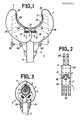
- a clamping device 1 of link in the form of a sticky tape 2 on a bundle of elements such as a bundle 3 of electrical wires 4, comprises according to the invention, a movable support 5 on which are mounted at least two jaws diametrically opposite, 6 and 7, at least one being movable and pivoting at one of its ends, which, on the one hand carry in their surfaces intended to receive these electrical elements or wires 4, a sticky tape 2 with an oriented sticky face towards the outside, and on the other hand in their closing movement by approaching one another, surround these elements or electrical wires 4 assembled in bundle 3, enclose them and pose this sticky tape 2 around this bundle 3 , and in their opening movement by separation from one another, release this bundle of elements linked by this sticky tape.
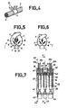
- the two diametrically opposite jaws 6 and 7 of the laying clamp 1 are respectively pivotable at one of their ends around two parallel spaced axes fixed fixed 11, 12.
- the adhesive tape 2 with a sticky face is chosen from adhesive tapes and iron-on tapes.
- the movable and pivoting jaws 6 and 7 respectively comprise in their pivoting ends, sliding slots 9 and 10 for on the one hand pivot axes 11 and 12 of these jaws and on the other hand elastic devices such as springs 13 and 14 which bear on one side on these fixed axes 11 and 12 and on the opposite side on the outer ends 19, 20 of these slots 9 and 10 and thus elastically and constantly recall the inner ends 17, 18 of these slots 9 and 10 of these jaws towards the fixed pivot axes 11 and 12.
- the elastic devices or springs 13 and 14 thus force the jaws 6 and 7 to operate or to pivot around the points closest to the interior ends 17, 18 of the slots 9 and 10 of these jaws. These means allow the jaws 6 and 7 to easily and correctly place links as well on bundles 3 of electrical elements or wires having a small diameter ( Figure 6) than those having a larger diameter ( Figure 5).
- the movable and pivoting jaws 6 and 7 are controlled in their movement by mechanical systems with jacks and rods of a known type, schematically indicated in 22, 23. Under the action of the systems with jacks and rods 22 and 23, the jaws 6 and 7 can pivot from their open position schematically shown in Figure 1, to their closed position illustrated in Figure 3, and vice versa.
- the movable and pivoting jaws 6 and 7 comprise in their receiving surfaces 29, 31 holding cells 25, 26 connected respectively to channels 27, 28 in which a depression is created by a known means schematically indicated in 30.
- the cells 25 and 26 placed under vacuum are intended to maintain the sticky tape 2 on the jaws 6 and 7, the single sticky face of this tape 2 being oriented towards the outside of the latter.
- the jaws 6 and 7 are provided in their receiving surfaces 29, 31 with known heating means, not shown, which make the sticky face of this fusible tape adherent.
- the bonding clamp 1 In a bonding operation on bundles 3 of electrical elements or wires 4, the bonding clamp 1 is, via its movable support 5, presented with jaws 6 and 7 open, to a distributor of known type not shown of sticky tapes for receiving a sticky tape 2 which is held by cells 25 and 26 placed under vacuum. The link-laying clamp 1 is then directed onto electrical elements or wires 4, and as soon as contact is established with these, its jaws 6 and 7 close under the control of the systems with jacks and links 22, 23.
- the jaws 6 and 7 enclose the bundle 3 of electrical elements or wires 4 and pose around the latter the sticky tape 2, the remaining projecting ends of which with adhesive face meet at the end of the closing stroke of these jaws 6 and 7, stick one against the other and thus reinforce the solidity of the maintenance of this bundle 3.
- the placing under vacuum of the cells 25, 26 is interrupted, and the jaws 6 and 7 of the link laying clamp 1, under the control systems with jacks and links 22, 23 open and release the bundle 3 linked by the sticky tape 2, and the link-laying clamp 1 withdraws to start another link-laying operation.
- the ends of the jaws 6 and 7 are cut into spaced parallel blades which intersect at the end of their closing stroke ( Figures 3.5 and 6).
- the jaw 6 comprises at its free end for example two spaced blades while the jaw 7 carries at its free end three spaced blades.
- the edges of the spaced blades of these jaws 6 and 7 are cut into cutting edges and adjusted to each other in their intersection in the manner of scissors.
- the ends of these jaws intersect to better grip this bundle of electrical elements or wires 3 and simultaneously cut the protruding glued ends of the adhesive tape 2, into strips 32 so as to facilitate good application of this strip on the periphery of this bundle 3.
- the jaws 6 and 7 have curvilinear surfaces 29, 31 for receiving the adhesive tape 2 and the electrical elements or wires 4.
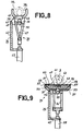
- a link plier 35 on a bundle 3 of electrical elements or wires 4 comprises a movable support 36 on which are mounted a pair of central jaws mobile 37 for applying sticky tape, and two pairs of mobile lateral jaws 38, 39 for bundling 3 of the electrical elements or wires 4.
- the movable support 36 comprises a body 40 having a L-shaped cross section and a head 41 provided with several spaced, parallel fins, four for example 42, 43, 44, 45. These fins parallel spaced are intended to support fixed spaced pivot axes 47, 48 of the pairs of jaws 37, 38, 39.
- the parallel fins 42, 43, 44, 45 are reinforced in their rigidity by a mechanical cross-member 50.
- the central jaws 37 which have a U-shaped cross section, are (FIG. 9) mounted diametrically opposite, pivoting at one of their ends respectively around two parallel spaced fixed axes, 47, 48 and filled with an elastic material 51, 52 such as elastic plastic foam.
- the central jaws 37 are controlled in their movement, from their open position shown in solid lines in FIG. 9 to their closed position shown in broken lines, and vice versa by a mechanical system 54 with actuator 55 and rods 56.
- the central jaws 37 are provided in their receiving surfaces formed by their longitudinal and transverse edges 57, with holding cells 58 connected to the channels 59 in which a depression is created by known means not shown.
- the cells 58 placed under vacuum are intended to maintain a sticky tape 60 on the jaws 37, the single sticky face of this tape 60 being oriented towards the outside of the latter.
- Alveoli 61 are created in a crosspiece 62 formed in the space between the pivot axes 47, 48 of the jaws 37, and placed under vacuum for additional support of the adhesive tape 60 in its central zone.
- the pairs of lateral jaws 38, 39 intended to hold a bundle 3 of the electrical elements or wires 4 each comprise two diametrically opposed jaws 38, 39 respectively pivoting at one of their ends around two parallel, spaced, fixed axes 47, 48
- Each of these two jaws 38 or 39 is formed of two spaced parallel elements 38a, 38b or 39a, 39b and having curvilinear receiving surfaces 38c, 39c.
- the pairs of lateral jaws 38, 39 are controlled, in their movement, respectively by mechanical systems with jacks 65, 66 and with rods 67, 68 from their open position shown in solid lines in Figure 8, to their closed position illustrated in broken lines, and vice versa.
- the bonding clamp 35 is presented with central jaws 37 and side jaws 38, 39 open, to a dispenser of adhesive tapes to receive a ribbon 60 which is held by pressurized cells 58 and 61 of the central jaws and of the cross-member 62.
- the link-laying clamp 35 is then directed onto electrical elements or wires 4 and as soon as contact with them is established, its lateral jaws 38, 39 close, enclose them and keep them assembled in a bundle 3, then its central jaws 37 in turn close on this bundle 3 and the elastic materials 51, 52 which fill these jaws while being deformed exert a pressure on this bundle and apply close the sticky tape 60 on the periphery of this bundle, and one against the other the remaining projecting ends with sticky faces of this sticky tape 60.
- the link laying operation carried out by the clamp 1 or 35 is thus quick and easily mechanizable or automated without the quality and solidity of the link being placed being compromised. Since the structure and operation of the clamp 1 or 35 described above are simple, the cost price and the installation cost of this clamp prove to be particularly economical.
Landscapes
- Engineering & Computer Science (AREA)
- Mechanical Engineering (AREA)
- Package Frames And Binding Bands (AREA)
- Basic Packing Technique (AREA)
- Clamps And Clips (AREA)
- Adhesive Tapes (AREA)
- Adhesives Or Adhesive Processes (AREA)
- Forklifts And Lifting Vehicles (AREA)
- Load-Engaging Elements For Cranes (AREA)
- Knitting Machines (AREA)
Priority Applications (1)
| Application Number | Priority Date | Filing Date | Title |
|---|---|---|---|
| AT87402312T ATE64346T1 (de) | 1986-10-17 | 1987-10-16 | Zange zum anlegen eines bandes um ein buendel von elementen. |
Applications Claiming Priority (2)
| Application Number | Priority Date | Filing Date | Title |
|---|---|---|---|
| FR8614420A FR2605260B1 (fr) | 1986-10-17 | 1986-10-17 | Pince-poseuse de lien sur un faisceau d'elements |
| FR8614420 | 1986-10-17 |
Publications (2)
| Publication Number | Publication Date |
|---|---|
| EP0267830A1 true EP0267830A1 (de) | 1988-05-18 |
| EP0267830B1 EP0267830B1 (de) | 1991-06-12 |
Family
ID=9339930
Family Applications (1)
| Application Number | Title | Priority Date | Filing Date |
|---|---|---|---|
| EP87402312A Expired - Lifetime EP0267830B1 (de) | 1986-10-17 | 1987-10-16 | Zange zum Anlegen eines Bandes um ein Bündel von Elementen |
Country Status (5)
| Country | Link |
|---|---|
| EP (1) | EP0267830B1 (de) |
| AT (1) | ATE64346T1 (de) |
| DE (1) | DE3770765D1 (de) |
| ES (1) | ES2022413B3 (de) |
| FR (1) | FR2605260B1 (de) |
Cited By (2)
| Publication number | Priority date | Publication date | Assignee | Title |
|---|---|---|---|---|
| DE102014019506A1 (de) * | 2014-12-23 | 2016-06-23 | Hermann Reuschenbach | Vorrichtung und Verfahren zur Herstellung von Fadenbündeln |
| US10457429B1 (en) | 2016-09-03 | 2019-10-29 | Johnson International Corporation | Pair of jaws for a twist-tying machine |
Citations (11)
| Publication number | Priority date | Publication date | Assignee | Title |
|---|---|---|---|---|
| US3031368A (en) * | 1961-02-08 | 1962-04-24 | Automatic Spot Taping Machine | Taping machine |
| US3063212A (en) * | 1960-10-20 | 1962-11-13 | Possis Machine Corp | Taping machine |
| US3242850A (en) * | 1962-11-14 | 1966-03-29 | Republic Steel Corp | Adhesive tape applying mechanism for bundling machines |
| US3988102A (en) * | 1975-11-10 | 1976-10-26 | Amp Incorporated | Crimpable plastic bundle tie |
| US4003189A (en) * | 1975-04-18 | 1977-01-18 | Bundy Corporation | Bundling mechanism |
| DE2555710A1 (de) * | 1975-12-11 | 1977-06-23 | Beiersdorf Ag | Zange zum banderolieren von gegenstaenden |
| EP0039188A1 (de) * | 1980-04-29 | 1981-11-04 | Lansing Bagnall Limited | Pneumatisch arbeitender Applikator und Verfahren zum Anbringen eines Klebebandes |
| US4360400A (en) * | 1981-07-06 | 1982-11-23 | Amp Incorporated | Apparatus for binding conductors in a harness |
| WO1984001349A1 (en) * | 1982-09-30 | 1984-04-12 | Boeing Co | Tying machine and method |
| GB2137582A (en) * | 1983-04-08 | 1984-10-10 | Sullivan Denis P O | An automatic bundle-tying tool |
| EP0121878A1 (de) * | 1983-04-06 | 1984-10-17 | Japan Bano'k Co. Ltd. | Kabelbündelvorrichtung |
-
1986
- 1986-10-17 FR FR8614420A patent/FR2605260B1/fr not_active Expired
-
1987
- 1987-10-16 EP EP87402312A patent/EP0267830B1/de not_active Expired - Lifetime
- 1987-10-16 DE DE8787402312T patent/DE3770765D1/de not_active Expired - Fee Related
- 1987-10-16 ES ES87402312T patent/ES2022413B3/es not_active Expired - Lifetime
- 1987-10-16 AT AT87402312T patent/ATE64346T1/de not_active IP Right Cessation
Patent Citations (11)
| Publication number | Priority date | Publication date | Assignee | Title |
|---|---|---|---|---|
| US3063212A (en) * | 1960-10-20 | 1962-11-13 | Possis Machine Corp | Taping machine |
| US3031368A (en) * | 1961-02-08 | 1962-04-24 | Automatic Spot Taping Machine | Taping machine |
| US3242850A (en) * | 1962-11-14 | 1966-03-29 | Republic Steel Corp | Adhesive tape applying mechanism for bundling machines |
| US4003189A (en) * | 1975-04-18 | 1977-01-18 | Bundy Corporation | Bundling mechanism |
| US3988102A (en) * | 1975-11-10 | 1976-10-26 | Amp Incorporated | Crimpable plastic bundle tie |
| DE2555710A1 (de) * | 1975-12-11 | 1977-06-23 | Beiersdorf Ag | Zange zum banderolieren von gegenstaenden |
| EP0039188A1 (de) * | 1980-04-29 | 1981-11-04 | Lansing Bagnall Limited | Pneumatisch arbeitender Applikator und Verfahren zum Anbringen eines Klebebandes |
| US4360400A (en) * | 1981-07-06 | 1982-11-23 | Amp Incorporated | Apparatus for binding conductors in a harness |
| WO1984001349A1 (en) * | 1982-09-30 | 1984-04-12 | Boeing Co | Tying machine and method |
| EP0121878A1 (de) * | 1983-04-06 | 1984-10-17 | Japan Bano'k Co. Ltd. | Kabelbündelvorrichtung |
| GB2137582A (en) * | 1983-04-08 | 1984-10-10 | Sullivan Denis P O | An automatic bundle-tying tool |
Cited By (3)
| Publication number | Priority date | Publication date | Assignee | Title |
|---|---|---|---|---|
| DE102014019506A1 (de) * | 2014-12-23 | 2016-06-23 | Hermann Reuschenbach | Vorrichtung und Verfahren zur Herstellung von Fadenbündeln |
| DE102014019506B4 (de) * | 2014-12-23 | 2017-07-13 | FilaTech Filament Technology u. Spinnanlagen GmbH | Vorrichtung und Verfahren zur Herstellung von Fadenbündeln |
| US10457429B1 (en) | 2016-09-03 | 2019-10-29 | Johnson International Corporation | Pair of jaws for a twist-tying machine |
Also Published As
| Publication number | Publication date |
|---|---|
| ES2022413B3 (es) | 1991-12-01 |
| FR2605260A1 (fr) | 1988-04-22 |
| EP0267830B1 (de) | 1991-06-12 |
| DE3770765D1 (de) | 1991-07-18 |
| ATE64346T1 (de) | 1991-06-15 |
| FR2605260B1 (fr) | 1988-12-09 |
Similar Documents
| Publication | Publication Date | Title |
|---|---|---|
| EP0366512B1 (de) | Kabelentmantelungswerkzeug | |
| FR2547233A1 (fr) | Pinces transformables pour tenue d'anneau | |
| EP3592507A1 (de) | Klemmgreifvorrichtung und system aus solchen vorrichtungen | |
| FR2478516A1 (fr) | Outil comportant deux mors solidaires de deux machoires et un dispositif d'entrainement relie a au moins l'une de ces machoires | |
| FR2596948A1 (fr) | Appareil a ebrancher les troncs d'arbres | |
| FR2499431A1 (fr) | Pince a sertir | |
| FR2535913A1 (fr) | Pince a denuder pour extremites de conducteurs | |
| EP0267830B1 (de) | Zange zum Anlegen eines Bandes um ein Bündel von Elementen | |
| EP1310717A1 (de) | Spannband | |
| WO1993003518A1 (fr) | Dispositif pour assembler par soudage et pour isoler des extremites assemblees de fils electriques | |
| EP0187061B1 (de) | Vorrichtung zu einer gelenkigen Verbindung von zwei ergänzenden Reihen von Verbindungshaken | |
| FR2657745A1 (fr) | Dispositif d'attache de plantes. | |
| EP0146471B1 (de) | Verfahren und Vorrichtung zur halbpermanenten Verbindung von optischen Fasern | |
| EP2006962A1 (de) | Spender- und Crimpzange für Verkabelungszubehör zum Aufcrimpen auf ein Kabel | |
| FR2678116A1 (fr) | Pinces de manipulation de fil, procede et dispositif de fabrication de faisceaux electriques utilisant ces pinces. | |
| EP0419748B1 (de) | Kombiniertes Werkzeug zum Schneiden und Abisolieren von Enden von elektrischen Kabeln, welche in einem isolierenden Mantel eingeschlossen sind | |
| FR2749210A1 (fr) | Outil de decoupe de cables contenant des fibres optiques | |
| WO2003043154A1 (fr) | Nouveau dispositif d'attache pour conducteurs electriques | |
| WO2020021167A1 (fr) | Machine d'application de fibres avec tubes flexibles d'acheminement de fibres munis de lames flexibles particulieres | |
| FR2835360A1 (fr) | Outil d'engainage d'au moins un cable dans une gaine fendue longitudinalement, et dispositif d'engainage comportant un tel outil | |
| EP3520185B1 (de) | Klemme zum einsetzen eines biegeelastischen strangs in einen behälter zur aufnahme des stranges über eine öffnung | |
| EP4572021A1 (de) | Isolationsdurchdringender verbinder | |
| FR3140574A1 (fr) | Machine d’application de fibres avec moyens d’acheminement de fibres particuliers | |
| FR3145459A1 (fr) | Fourche à pince et moyens de coupe, véhicule équipé d’une telle fourche | |
| FR2477424A1 (fr) | Pince pour le maintien de la tension des cordes lors d'une operation de cordage d'une raquette de tennis ou article similaire |
Legal Events
| Date | Code | Title | Description |
|---|---|---|---|
| PUAI | Public reference made under article 153(3) epc to a published international application that has entered the european phase |
Free format text: ORIGINAL CODE: 0009012 |
|
| AK | Designated contracting states |
Kind code of ref document: A1 Designated state(s): AT BE CH DE ES FR GB IT LI LU NL SE |
|
| 17P | Request for examination filed |
Effective date: 19881017 |
|
| 17Q | First examination report despatched |
Effective date: 19901026 |
|
| GRAA | (expected) grant |
Free format text: ORIGINAL CODE: 0009210 |
|
| AK | Designated contracting states |
Kind code of ref document: B1 Designated state(s): AT BE CH DE ES FR GB IT LI LU NL SE |
|
| REF | Corresponds to: |
Ref document number: 64346 Country of ref document: AT Date of ref document: 19910615 Kind code of ref document: T |
|
| ITF | It: translation for a ep patent filed | ||
| REF | Corresponds to: |
Ref document number: 3770765 Country of ref document: DE Date of ref document: 19910718 |
|
| GBT | Gb: translation of ep patent filed (gb section 77(6)(a)/1977) | ||
| PLBE | No opposition filed within time limit |
Free format text: ORIGINAL CODE: 0009261 |
|
| STAA | Information on the status of an ep patent application or granted ep patent |
Free format text: STATUS: NO OPPOSITION FILED WITHIN TIME LIMIT |
|
| 26N | No opposition filed | ||
| PGFP | Annual fee paid to national office [announced via postgrant information from national office to epo] |
Ref country code: CH Payment date: 19920910 Year of fee payment: 6 |
|
| PGFP | Annual fee paid to national office [announced via postgrant information from national office to epo] |
Ref country code: SE Payment date: 19920917 Year of fee payment: 6 Ref country code: DE Payment date: 19920917 Year of fee payment: 6 |
|
| PGFP | Annual fee paid to national office [announced via postgrant information from national office to epo] |
Ref country code: GB Payment date: 19920918 Year of fee payment: 6 |
|
| PGFP | Annual fee paid to national office [announced via postgrant information from national office to epo] |
Ref country code: BE Payment date: 19920925 Year of fee payment: 6 |
|
| PGFP | Annual fee paid to national office [announced via postgrant information from national office to epo] |
Ref country code: ES Payment date: 19921002 Year of fee payment: 6 |
|
| PGFP | Annual fee paid to national office [announced via postgrant information from national office to epo] |
Ref country code: LU Payment date: 19921015 Year of fee payment: 6 |
|
| PGFP | Annual fee paid to national office [announced via postgrant information from national office to epo] |
Ref country code: FR Payment date: 19921019 Year of fee payment: 6 |
|
| PGFP | Annual fee paid to national office [announced via postgrant information from national office to epo] |
Ref country code: AT Payment date: 19921030 Year of fee payment: 6 |
|
| PGFP | Annual fee paid to national office [announced via postgrant information from national office to epo] |
Ref country code: NL Payment date: 19921031 Year of fee payment: 6 |
|
| EPTA | Lu: last paid annual fee | ||
| PG25 | Lapsed in a contracting state [announced via postgrant information from national office to epo] |
Ref country code: LU Free format text: LAPSE BECAUSE OF NON-PAYMENT OF DUE FEES Effective date: 19931016 Ref country code: GB Effective date: 19931016 Ref country code: AT Effective date: 19931016 |
|
| PG25 | Lapsed in a contracting state [announced via postgrant information from national office to epo] |
Ref country code: SE Effective date: 19931017 |
|
| PG25 | Lapsed in a contracting state [announced via postgrant information from national office to epo] |
Ref country code: ES Free format text: LAPSE BECAUSE OF EXPIRATION OF PROTECTION Effective date: 19931018 |
|
| PG25 | Lapsed in a contracting state [announced via postgrant information from national office to epo] |
Ref country code: LI Effective date: 19931031 Ref country code: CH Effective date: 19931031 Ref country code: BE Effective date: 19931031 |
|
| BERE | Be: lapsed |
Owner name: CIAPEM Effective date: 19931031 |
|
| PG25 | Lapsed in a contracting state [announced via postgrant information from national office to epo] |
Ref country code: NL Effective date: 19940501 |
|
| GBPC | Gb: european patent ceased through non-payment of renewal fee |
Effective date: 19931016 |
|
| NLV4 | Nl: lapsed or anulled due to non-payment of the annual fee | ||
| PG25 | Lapsed in a contracting state [announced via postgrant information from national office to epo] |
Ref country code: FR Effective date: 19940630 |
|
| REG | Reference to a national code |
Ref country code: CH Ref legal event code: PL |
|
| PG25 | Lapsed in a contracting state [announced via postgrant information from national office to epo] |
Ref country code: DE Effective date: 19940701 |
|
| REG | Reference to a national code |
Ref country code: FR Ref legal event code: ST |
|
| EUG | Se: european patent has lapsed |
Ref document number: 87402312.0 Effective date: 19940510 |
|
| REG | Reference to a national code |
Ref country code: ES Ref legal event code: FD2A Effective date: 19990601 |
|
| PG25 | Lapsed in a contracting state [announced via postgrant information from national office to epo] |
Ref country code: IT Free format text: LAPSE BECAUSE OF NON-PAYMENT OF DUE FEES;WARNING: LAPSES OF ITALIAN PATENTS WITH EFFECTIVE DATE BEFORE 2007 MAY HAVE OCCURRED AT ANY TIME BEFORE 2007. THE CORRECT EFFECTIVE DATE MAY BE DIFFERENT FROM THE ONE RECORDED. Effective date: 20051016 |