EP0268406A2 - Appareil de séquençage biochimique - Google Patents
Appareil de séquençage biochimique Download PDFInfo
- Publication number
- EP0268406A2 EP0268406A2 EP87309798A EP87309798A EP0268406A2 EP 0268406 A2 EP0268406 A2 EP 0268406A2 EP 87309798 A EP87309798 A EP 87309798A EP 87309798 A EP87309798 A EP 87309798A EP 0268406 A2 EP0268406 A2 EP 0268406A2
- Authority
- EP
- European Patent Office
- Prior art keywords
- electrodes
- gel
- plate
- electrophoresis
- detector
- Prior art date
- Legal status (The legal status is an assumption and is not a legal conclusion. Google has not performed a legal analysis and makes no representation as to the accuracy of the status listed.)
- Withdrawn
Links
Images


Classifications
-
- G—PHYSICS
- G01—MEASURING; TESTING
- G01N—INVESTIGATING OR ANALYSING MATERIALS BY DETERMINING THEIR CHEMICAL OR PHYSICAL PROPERTIES
- G01N27/00—Investigating or analysing materials by the use of electric, electrochemical, or magnetic means
- G01N27/26—Investigating or analysing materials by the use of electric, electrochemical, or magnetic means by investigating electrochemical variables; by using electrolysis or electrophoresis
- G01N27/416—Systems
- G01N27/447—Systems using electrophoresis
- G01N27/44704—Details; Accessories
- G01N27/44717—Arrangements for investigating the separated zones, e.g. localising zones
- G01N27/4473—Arrangements for investigating the separated zones, e.g. localising zones by electric means
Definitions
- This invention relates to apparatus for sequencing and, in particular, biochemical sequencing.
- Sequencing of macromolecules for example nucleic acids such as DNA, is usually carried out by biochemical fragmentation, followed by gel electrophoresis. The sequence is detected by exposure of the gel to autoradiographic film to give a two dimensional picture from which the sequence of individual nucleotide bases can be read.
- There are currently two main techniques used for fragmentation the Maxam-Gilbert method involving the cleavage of the DNA molecule by a two-stage addition of chemicals, and the Sanger method involving the preparation of separate samples of dideoxynucleotide of each of the four bases C, G, A and T and then the growth of a complementary DNA strand to that of the DNA under test using an enzyme.
- Both techniques end up with four different samples, enabling identification of the four bases, each containing fragments of different lengths.
- a radioactive or fluorescent label is attached to each fragment to enable detection of the sequence using autoradiography.
- electrophoresis the four different sets of labelled fragments are each placed in a separate well and thus generate a separate and distinct track across the gel as the electrophoresis proceeds. After the electrophoresis has finished, the gel is separated and dried and is then exposed to autoradiographic film to obtain an image of the pattern of labelled fragments of different length and belonging to different nucleotide groups.
- the requirement for autoradiography is eliminated by direct detection of events occurring within the electrophoresis gel. This can either be done as electrophoresis proceeds by means of a stationary large are a solid state detector or a completed electrophoresis gel can be scanned by such a detector.
- the detector comprises a plate of pure semiconductor material such as silicon, gallium arsenide, mercuric iodine or mercuric telluride, which has been cut from a single crystal. Mounted on both sides of the plate are electrodes which are arranged in different patterns according to the type of detector - examples will be described in more detail hereinafter.
- a well researched example of such a detector is the silicon detector which is fabricated from a plate of high resistivity silicon having a resistivity greater that 3000 ⁇ cm and preferably 5000 ⁇ cm.
- a plurality of parallel spaced strip electrodes are attached to at least one face of the plate. These strips are connected to detection electronics operable to provide a readout of the detector output.
- the other face of the plate may be provided with a solid metallic substrate or a further plurality of parallel strip electrodes which are parallel to the electrodes on the first-mentioned face.
- a potential gradient is applied across the plate - as will be explained in more detail hereinafter - in order to deplete the plate material of minority carriers in order to eliminate non-linear effects in the readout.
- a charged particle or photon traversing the plate produces within the semiconductor material electron-hole pairs which traverse towards the electrodes on one face or the other depending upon the direction of the electric field set up by the aforsaid potential gradient. This causes a pulse of current to flow in the electrode(s) concerned and may thus be picked up and analysed by the associated electronics. The more energetic the particle, the greater the number of hole-electron pairs that are released, and the greater the amplitude of the current pulse which results.
- the pitch of the strip electrodes is typically 20 ⁇ m which can achieve a readout resolution in the region of 3 ⁇ m.
- the detector is placed parallel to and a short distance from the surface of the electrophoresis gel.
- bands of radioactivity each representing a group of fragments of particular length, will emerge from the wells and traverse the gel, passing the detector.
- four parallel tracks each representing a nucleotide group, will enable complete characterisation of the DNA molecule, and the detector is arranged in such a way that the strip electrodes are at right angles to the direction of the tracks so that the bands of radioactivity, as they proceed along the tracks, will cross the strip electrodes of a stationary detector and will thus generate output signals in the electrodes representive of the sequencing pattern.
- one sheet of semiconductor material can be formed with separate sets of electrodes in such a way as to make four distinct detectors. This latter can be achieved either by forming an entirely separate set of strip electrodes for each track or, in the case of silicon drift detectors (see below), by means of strip electrodes covering all four tracks with a separate anode for each track.
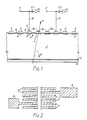
- the detector comprises a plate 1 of high purity n-type silicon cut from a single crystal and typically of 280 ⁇ m thickness.
- p+ material 2 such as boron are strip electrodes 3 with a pitch of typically 20 ⁇ m.
- An insulating layer 4 of silicon dioxide is applied to the exposed area of the crystal.
- n+ material 5 such as arsenic is a continuous backplane 6 of aluminium, typically l ⁇ m thick.
- the backplane 6 can also take the form of a plurality of strip electrodes orientated orthogonally to electrodes 3, as will be explained later.
- the connection from each strip electrode 3 through the silicon to the backplane is electrically equivalent to two series-connected diodes.
- a potential difference, typically one hundred volts, is applied between the backplane and the terminals 7 in a direction such as to reverse bias these diodes. This potential clears out any minority carriers from the silicon and also sets up an electric field within the silicon to control the movement of electrons and holes - see below.
- Each terminal 7 is connected to an associated strip electrode 3 by means of a lead 8. Also connected to the lead 8 is the input of readout electronics for each strip, to be described in more detail later.
- the readout electronics is represented by an isolating capacitor C1 and an amplifier A1.
- Each lead 8 is connected to its associated strip electrode 3 by means of a connection pad 9 (see Figure 2). It will be noted that not every strip electrode 3 has a connection pad, this being in order to reduce the complexity of the readout electronics. It has been found that it is not essential to connect a lead 8 to all strip electrodes 3, the only penalty being a small reduction in spatial resolution. For example, for a strip electrode pitch of 20 ⁇ m, the spatial resolution can be 3 ⁇ m if all electrodes are connected; for a connection pitch of 60 ⁇ m - i.e. every third electrode connected - the spatial resolution falls to 4.5 ⁇ m. Where not all electrodes are connected, the unconnected electrodes utilise the principle of capacitive charge division to transfer the signal to the nearest connected readouts. A resistive connection is also made between all of the electrodes to ensure that they are all at substantially the same potential with respect to the backplane 6 in order to achieve a uniform electric field distribution within the silicon plate 1.
- Typical readout electronics is illustrated diagrammatically in Figure 3.
- the output from each connection pad 9 is amplified in amplifier A1 and stored temporarily in capacitor C store .
- a shift register 10 cycles round the various channels closing, as it does so, a switch S1 for each channel and applying, if there is a signal present on capacitor C store , a +5V level to an output bus 11.
- a serial signal representative of a continuous sequential scanning of the strip electrodes 3.
- FIG 4. An alternative type of detector, known as the silicon drift detector, is shown in Figure 4.
- the construction is very similar to that described above with reference to Figures 1 and 2, with the exception that the continuous backplane 6 is replaced by a further plurality of strip electrodes 12 similar to electrodes 3, and with each electrode 12 placed opposite to a corresponding electrode 3. Also, the rightmost upper strip electrode is connected as an anode 13.
- the operation of the drift detector relies on achieving an electric field distribution within the silicon plate 1 which causes the electrons, once liberated by passage of a particle or photon (see arrow A), to move or “drift" in a rightwards direction along the path indicated by arrow B, eventually to be collected by the anode 13.
- the holes meanwhile flow to the nearest strip electrode 3 and/or 12.
- a current is set up between the anode 13 and one or more strip electrodes 3 or 12.
- the desired electron drift is achieved by correct choice of the potentials on the strip electrodes 3 and 12.
- the electrodes on the top and bottom are in oppositely-disposed pairs; the potentials are arranged such that the electrodes 3 and 12 of each such pair have the same potential so that there is no component of electric field directly across the silicon plate 1.
- Each set of plates is, however, at a different potential to the next, providing a continuous rising or falling potential gradient as one moves along the plate 1.
- the anode 13, for example might be at ground potential, with the next adjacent strip electrode 3 and its corresponding opposite electrode 12 at a negative potential of 100 volts.
- the next pair 3, 12 of strip electrodes will have a higher negative potential, say 110 volts, and so on to the left-hand end of the detector.
- the electric field distribution which results acts effectively as a sloping "gutter", positioned along the centre of the silicon plate, along which liberated electrons flow from left to right in Figure 4.
- the field distribution is distorted in such a way as to cause the electrons to flow into the anode, as mentioned above.
- drift detector can be configured as a multi-anode detector, enabling detection of events in two dimensions.
- a detector is illustrated diagrammatically in Figure 5 which is a view of the top surface showing only the strip electrodes 3 (the electrodes 12 being hidden), together with a plurality of anodes 13. Both the anodes 13 and the strip electrodes 3 and 12 are connected to suitable readout electronics (not shown).
- FIGS. 6 and 7 show the use of silicon detectors of the type described above in an electrophoresis apparatus.
- the basic form of the electrophoresis apparatus is standard and will not be described in detail.
- the apparatus comprises a pair of glass plates 14,15 between which is sandwiched a layer 16 of polyacrylamide gel, typically 0.4 mm thick. Formed in the top surface of the gel are four separate wells 17 which each carry a sample to be analysed.
- the right-hand glass plate 15 extends beyond the left hand plate 14 at top and bottom in order to define one wall of a respective reservoir 18,19 containing a salt solution 20 which allows conduction of current between electrodes 23 and 24 upon application of a suitable voltage across terminals 21, 22.
- the current flow is by way of the layer 16 of gel which is in contact with the salt solution at top and bottom.
- a sample to be analysed is fragmented in the manner described above to give the four different sub-samples required to enable identification of the four bases.
- One sub-sample is placed in each well 17 and a potential applied across the terminals 21,22.
- the gel acts as a skeletal foam in which are formed pores through which the material of the samples can pass under the influence of the electric current.
- the action of the current causes the fragments to migrate through the gel, forming a distinct track emanating from each well, and travelling downwards towards the bottom of the gel.
- the fragments formed by the fragmentation process tend to travel through in groups of identical length, those groups containing the shorter length fragments tending to travel faster through the gel than those containing the longer length fragments.
- the different groups tend to be bunched up near the top of the gel - i.e. nearest the well - but as they travel down the gel they become spread out because they are travelling at different speeds.
- the progress of the fragments through the gel is, of course, invisible to the naked eye but dyes can be used to enable visual monitoring of progress.
- plate 15 - Set into one of the plates of glass - in this case plate 15 - is a large-area silicon detector 25 such as one of the types described above.
- a thin layer 26, for example of polyimide, lies between the gel surface and the detector itself, but the detector is otherwise as close as possible to the gel surface.
- the detector 25 is orientated in such a way that the strip electrodes 3 lie orthogonally to the tracks formed during electrophoresis. Thus, as electrophoresis proceeds, the bands formed by the groups of identically dimensioned fragments move across the strips.
- the spacing of the anodes 13 will be such that they each overlie a single track - thus, for a four track electrophoresis apparatus, a four-anode detector will be needed.
- the detector of Figure 1 is somewhat more of a problem since, as shown, it is clearly unsuitable for monitoring more than a single track.
- One solution is to provide an individual detector, let into glass plate 15, for each track.
- the detectors can be completely separate entities or can be formed as separate sets of electrodes on a common silicon plate 1.
- a further alternative is to divide up the aluminium backplane 6 into mutually insulated strips extending orthogonally to the strip electrodes 3.
- Each such backplane strip is positioned to overly a respective track but, in doing this, care must be taken not to too greatly distort the electric field pattern within the silicon, or resolution becomes impaired. To this end, the distance between these backplane strips is kept to a minimum - for example 6 to 10 ⁇ m.
- a picture can thus be built up of the sequence of nucleotide groups within the sample. This will involve clocking the groups of equal-length fragments as they proceed past the electrodes to provide information as to their speed of travel; this information can then be computed to indicate the position of the particular group at the end of the test even though the group will, by this time, probably have long past the detector.
- the multi-anode drift detector described in relation to Figures 4 and 5 and the split groundplane version of the strip detector of Figure 1 are both able, in addition to giving information as to the occurrence of events in the direction of the tracks, to give information as to the occurrence of events at right angles to the tracks - in other words, where the detector covers a plurality of tracks, is able to give information as to which track the event or events occur in.
- Suitable electronics can be used to analyse the results to give information as to the sequence of nucleotides in the original sample without the need for autoradiography followed by visual interpretation by a skilled operator.
- the system is thus more reliable, quicker and therefore, in the long run, cheaper than the existing techniques.
- Figure 7 shows the Figure 1 detector with the groundplane 6 adjacent the gel.
- the groundplane surface should be remote from the gel.
- the anodes may be on the surface nearest the gel or otherwise from the point of view of detector operation. Also the anodes may lead or trail the electrodes 3 in the direction of movement of the electrophoresis tracks.
- a simple detector with just a single strip electrode 3 would operate, a plurality of electrodes, for example 50, will give more informative results; in particular the velocity of travel of the groups of equal length fragments can be calculated, as mentioned above. It is even possible, with a multi electrode detector to incorporate a feedback loop to alter the electrophoresis conditions in order to improve speed and resolution. For example, if groups are too close together to be readily distinguished, it would be possible to slow down the speed of movement by automatically lowering the electrophoresis potential, and thus increase the spacing for improved detection by later strip electrodes.
- a further detector is placed, similarly to the first, in the other plate 14 of glass - see Figure 6 - in a position directly opposite the first.
Landscapes
- Health & Medical Sciences (AREA)
- Life Sciences & Earth Sciences (AREA)
- Molecular Biology (AREA)
- Chemical & Material Sciences (AREA)
- Chemical Kinetics & Catalysis (AREA)
- Electrochemistry (AREA)
- Physics & Mathematics (AREA)
- Analytical Chemistry (AREA)
- Biochemistry (AREA)
- General Health & Medical Sciences (AREA)
- General Physics & Mathematics (AREA)
- Immunology (AREA)
- Pathology (AREA)
- Investigating Or Analysing Biological Materials (AREA)
- Investigating, Analyzing Materials By Fluorescence Or Luminescence (AREA)
- Apparatus Associated With Microorganisms And Enzymes (AREA)
Applications Claiming Priority (2)
| Application Number | Priority Date | Filing Date | Title |
|---|---|---|---|
| GB8626575 | 1986-11-06 | ||
| GB868626575A GB8626575D0 (en) | 1986-11-06 | 1986-11-06 | Biochemical sequencing |
Publications (2)
| Publication Number | Publication Date |
|---|---|
| EP0268406A2 true EP0268406A2 (fr) | 1988-05-25 |
| EP0268406A3 EP0268406A3 (fr) | 1988-06-22 |
Family
ID=10606917
Family Applications (1)
| Application Number | Title | Priority Date | Filing Date |
|---|---|---|---|
| EP87309798A Withdrawn EP0268406A3 (fr) | 1986-11-06 | 1987-11-05 | Appareil de séquençage biochimique |
Country Status (4)
| Country | Link |
|---|---|
| EP (1) | EP0268406A3 (fr) |
| JP (1) | JPS63133051A (fr) |
| AU (1) | AU8082287A (fr) |
| GB (1) | GB8626575D0 (fr) |
Cited By (10)
| Publication number | Priority date | Publication date | Assignee | Title |
|---|---|---|---|---|
| WO1990000623A1 (fr) * | 1988-07-08 | 1990-01-25 | Wallac Oy | Analyse par fluorescence a resolution temporelle et marquage multiple de sequences d'acide nucleique, a l'aide de chelates de lanthanide |
| US4908112A (en) * | 1988-06-16 | 1990-03-13 | E. I. Du Pont De Nemours & Co. | Silicon semiconductor wafer for analyzing micronic biological samples |
| WO2002059365A1 (fr) * | 2001-01-12 | 2002-08-01 | Biomolex As | Procede et appareil de quantification simultanee de differents radionucleides a la surface d'un microreseau biologique |
| US6592735B1 (en) * | 1999-12-22 | 2003-07-15 | California Institute Of Technology | DNA sequencing machine with improved cooling characteristics |
| US6607886B2 (en) | 2001-02-01 | 2003-08-19 | Biomolex As | Method and apparatus for simultaneous quantification of different radionuclides in a large number of regions on the surface of a biological microarray or similar test objects |
| US7740747B2 (en) | 2007-12-28 | 2010-06-22 | General Electric Company | Injection method for microfluidic chips |
| US7740748B2 (en) | 2008-10-27 | 2010-06-22 | General Electric Company | Electrophoresis system and method |
| US7927476B2 (en) | 2008-12-22 | 2011-04-19 | General Electric Company | Injection method for microfluidic chips |
| US8029743B2 (en) | 2007-09-19 | 2011-10-04 | General Electric Company | Microfluidic device with vertical injection aperture |
| CN111562278A (zh) * | 2020-05-22 | 2020-08-21 | 江苏万略医药科技有限公司 | 一种定量全身放射自显影药物分布跟踪方法 |
Family Cites Families (5)
| Publication number | Priority date | Publication date | Assignee | Title |
|---|---|---|---|---|
| JPS6010174A (ja) * | 1983-06-29 | 1985-01-19 | Fuji Photo Film Co Ltd | オ−トラジオグラフイ−による遺伝子のスクリ−ニング方法 |
| JPH0610665B2 (ja) * | 1984-02-01 | 1994-02-09 | 株式会社日立製作所 | 核酸の塩基配列決定装置 |
| US4729947A (en) * | 1984-03-29 | 1988-03-08 | The Board Of Regents Of The University Of Nebraska | DNA sequencing |
| JPS60249059A (ja) * | 1984-05-25 | 1985-12-09 | Hitachi Ltd | 核酸塩基配列決定装置 |
| GB8432069D0 (en) * | 1984-12-19 | 1985-01-30 | Iq Bio Ltd | Apparatus for immunoassay |
-
1986
- 1986-11-06 GB GB868626575A patent/GB8626575D0/en active Pending
-
1987
- 1987-11-05 AU AU80822/87A patent/AU8082287A/en not_active Abandoned
- 1987-11-05 EP EP87309798A patent/EP0268406A3/fr not_active Withdrawn
- 1987-11-06 JP JP62280836A patent/JPS63133051A/ja active Pending
Cited By (10)
| Publication number | Priority date | Publication date | Assignee | Title |
|---|---|---|---|---|
| US4908112A (en) * | 1988-06-16 | 1990-03-13 | E. I. Du Pont De Nemours & Co. | Silicon semiconductor wafer for analyzing micronic biological samples |
| WO1990000623A1 (fr) * | 1988-07-08 | 1990-01-25 | Wallac Oy | Analyse par fluorescence a resolution temporelle et marquage multiple de sequences d'acide nucleique, a l'aide de chelates de lanthanide |
| US6592735B1 (en) * | 1999-12-22 | 2003-07-15 | California Institute Of Technology | DNA sequencing machine with improved cooling characteristics |
| WO2002059365A1 (fr) * | 2001-01-12 | 2002-08-01 | Biomolex As | Procede et appareil de quantification simultanee de differents radionucleides a la surface d'un microreseau biologique |
| US6607886B2 (en) | 2001-02-01 | 2003-08-19 | Biomolex As | Method and apparatus for simultaneous quantification of different radionuclides in a large number of regions on the surface of a biological microarray or similar test objects |
| US8029743B2 (en) | 2007-09-19 | 2011-10-04 | General Electric Company | Microfluidic device with vertical injection aperture |
| US7740747B2 (en) | 2007-12-28 | 2010-06-22 | General Electric Company | Injection method for microfluidic chips |
| US7740748B2 (en) | 2008-10-27 | 2010-06-22 | General Electric Company | Electrophoresis system and method |
| US7927476B2 (en) | 2008-12-22 | 2011-04-19 | General Electric Company | Injection method for microfluidic chips |
| CN111562278A (zh) * | 2020-05-22 | 2020-08-21 | 江苏万略医药科技有限公司 | 一种定量全身放射自显影药物分布跟踪方法 |
Also Published As
| Publication number | Publication date |
|---|---|
| GB8626575D0 (en) | 1986-12-10 |
| EP0268406A3 (fr) | 1988-06-22 |
| JPS63133051A (ja) | 1988-06-04 |
| AU8082287A (en) | 1988-05-19 |
Similar Documents
| Publication | Publication Date | Title |
|---|---|---|
| EP0830592B1 (fr) | Methode pour identifier des substances moleculaires | |
| US6333504B1 (en) | Semiconductor radiation detector with enhanced charge collection | |
| EP1219975B1 (fr) | Detecteur d'images a faisceau corpusculaire a amplification gazeuse par electrodes ponctuelles | |
| CN105339810B (zh) | 半导体闪烁探测器 | |
| EP0268406A2 (fr) | Appareil de séquençage biochimique | |
| Webster et al. | Monolithic capillary gel electrophoresis stage with on-chip detector | |
| US5777338A (en) | Ionization detector, electrode configuration and single polarity charge detection method | |
| US4967084A (en) | Multi-sample scintillation counter using position-sensitive detector | |
| US4904366A (en) | Instrument for determination of the base sequence of nucleic acid | |
| US3415992A (en) | Extended area semiconductor radiation detectors and a novel readout arrangement | |
| JPS63500412A (ja) | 水平解像度の改善されたフレ−ム転送ccd面積イメ−ジセンサ | |
| US6268605B1 (en) | Autoradiography imaging | |
| US4703168A (en) | Multiplexed wedge anode detector | |
| KR20030064741A (ko) | 폴리머를 특징짓고 시퀀싱하는 시스템 및 방법 | |
| JPH02227945A (ja) | ストリーク管ターゲット | |
| EP0270251A2 (fr) | Méthode et dispositif de formation d'image de rayonnement | |
| JPS63282658A (ja) | 核酸分子のような高複合分子をシーケンス分析する方法および装置 | |
| JPH01138486A (ja) | 多チャンネル型半導体放射線検出器 | |
| JPH0221284A (ja) | 粒子線検出装置 | |
| JP4870318B2 (ja) | 泳動対象の速度を決定するためのシステムおよび方法 | |
| JPH1144769A (ja) | 半導体放射線検出器 | |
| SU1481697A1 (ru) | Устройство считывани координатной информации с одномерных проволочных детекторов | |
| CA1254293A (fr) | Detecteur sans delimitation a lecture differentielle | |
| JPS6290980A (ja) | イオン検出素子及びイオン検出アレイ | |
| JPH02129583A (ja) | 放射線検出器 |
Legal Events
| Date | Code | Title | Description |
|---|---|---|---|
| PUAI | Public reference made under article 153(3) epc to a published international application that has entered the european phase |
Free format text: ORIGINAL CODE: 0009012 |
|
| PUAL | Search report despatched |
Free format text: ORIGINAL CODE: 0009013 |
|
| AK | Designated contracting states |
Kind code of ref document: A2 Designated state(s): AT BE CH DE ES FR GB IT LI LU NL SE |
|
| AK | Designated contracting states |
Kind code of ref document: A3 Designated state(s): AT BE CH DE ES FR GB IT LI LU NL SE |
|
| 17P | Request for examination filed |
Effective date: 19880816 |
|
| 17Q | First examination report despatched |
Effective date: 19901213 |
|
| STAA | Information on the status of an ep patent application or granted ep patent |
Free format text: STATUS: THE APPLICATION IS DEEMED TO BE WITHDRAWN |
|
| 18D | Application deemed to be withdrawn |
Effective date: 19910424 |
|
| RIN1 | Information on inventor provided before grant (corrected) |
Inventor name: FINLAN, MARTIN FRANCIS Inventor name: BRADY, MICHAEL ANTHONY WARBURTON |