EP0268720A1 - Gerüstplatte aus Kunststoff, Verfahren zu ihrer Herstellung und Vorrichtung zur Ausführung des Verfahrens - Google Patents
Gerüstplatte aus Kunststoff, Verfahren zu ihrer Herstellung und Vorrichtung zur Ausführung des Verfahrens Download PDFInfo
- Publication number
- EP0268720A1 EP0268720A1 EP86810534A EP86810534A EP0268720A1 EP 0268720 A1 EP0268720 A1 EP 0268720A1 EP 86810534 A EP86810534 A EP 86810534A EP 86810534 A EP86810534 A EP 86810534A EP 0268720 A1 EP0268720 A1 EP 0268720A1
- Authority
- EP
- European Patent Office
- Prior art keywords
- scaffolding
- parts
- mold
- scaffolding plate
- air
- Prior art date
- Legal status (The legal status is an assumption and is not a legal conclusion. Google has not performed a legal analysis and makes no representation as to the accuracy of the status listed.)
- Granted
Links
- 238000000034 method Methods 0.000 title claims abstract description 14
- 239000004033 plastic Substances 0.000 title claims abstract description 5
- 239000000463 material Substances 0.000 claims abstract description 9
- 238000004519 manufacturing process Methods 0.000 claims abstract description 7
- 239000002131 composite material Substances 0.000 claims abstract description 5
- 229920001187 thermosetting polymer Polymers 0.000 claims abstract 2
- XAGFODPZIPBFFR-UHFFFAOYSA-N aluminium Chemical compound [Al] XAGFODPZIPBFFR-UHFFFAOYSA-N 0.000 claims description 8
- 239000008187 granular material Substances 0.000 claims description 4
- 230000003014 reinforcing effect Effects 0.000 claims description 4
- 239000011347 resin Substances 0.000 claims description 4
- 229920005989 resin Polymers 0.000 claims description 4
- 239000011148 porous material Substances 0.000 claims description 3
- 239000000835 fiber Substances 0.000 claims 1
- 239000002985 plastic film Substances 0.000 claims 1
- 229910052751 metal Inorganic materials 0.000 abstract description 3
- 239000002184 metal Substances 0.000 abstract description 3
- 239000002023 wood Substances 0.000 abstract description 3
- 239000003365 glass fiber Substances 0.000 description 5
- 229910052782 aluminium Inorganic materials 0.000 description 3
- 239000011265 semifinished product Substances 0.000 description 3
- 239000004744 fabric Substances 0.000 description 2
- 239000000203 mixture Substances 0.000 description 2
- KQZLRWGGWXJPOS-NLFPWZOASA-N 1-[(1R)-1-(2,4-dichlorophenyl)ethyl]-6-[(4S,5R)-4-[(2S)-2-(hydroxymethyl)pyrrolidin-1-yl]-5-methylcyclohexen-1-yl]pyrazolo[3,4-b]pyrazine-3-carbonitrile Chemical compound ClC1=C(C=CC(=C1)Cl)[C@@H](C)N1N=C(C=2C1=NC(=CN=2)C1=CC[C@@H]([C@@H](C1)C)N1[C@@H](CCC1)CO)C#N KQZLRWGGWXJPOS-NLFPWZOASA-N 0.000 description 1
- 239000011324 bead Substances 0.000 description 1
- 229940125877 compound 31 Drugs 0.000 description 1
- 238000010438 heat treatment Methods 0.000 description 1
- 230000035699 permeability Effects 0.000 description 1
- 239000011435 rock Substances 0.000 description 1
- 238000004804 winding Methods 0.000 description 1
Images



Classifications
-
- B—PERFORMING OPERATIONS; TRANSPORTING
- B29—WORKING OF PLASTICS; WORKING OF SUBSTANCES IN A PLASTIC STATE IN GENERAL
- B29C—SHAPING OR JOINING OF PLASTICS; SHAPING OF MATERIAL IN A PLASTIC STATE, NOT OTHERWISE PROVIDED FOR; AFTER-TREATMENT OF THE SHAPED PRODUCTS, e.g. REPAIRING
- B29C51/00—Shaping by thermoforming, i.e. shaping sheets or sheet like preforms after heating, e.g. shaping sheets in matched moulds or by deep-drawing; Apparatus therefor
- B29C51/26—Component parts, details or accessories; Auxiliary operations
- B29C51/30—Moulds
- B29C51/36—Moulds specially adapted for vacuum forming, Manufacture thereof
- B29C51/365—Porous moulds
-
- E—FIXED CONSTRUCTIONS
- E04—BUILDING
- E04G—SCAFFOLDING; FORMS; SHUTTERING; BUILDING IMPLEMENTS OR AIDS, OR THEIR USE; HANDLING BUILDING MATERIALS ON THE SITE; REPAIRING, BREAKING-UP OR OTHER WORK ON EXISTING BUILDINGS
- E04G1/00—Scaffolds primarily resting on the ground
- E04G1/15—Scaffolds primarily resting on the ground essentially comprising special means for supporting or forming platforms; Platforms
- E04G1/153—Platforms made of plastics, with or without reinforcement
-
- B—PERFORMING OPERATIONS; TRANSPORTING
- B29—WORKING OF PLASTICS; WORKING OF SUBSTANCES IN A PLASTIC STATE IN GENERAL
- B29K—INDEXING SCHEME ASSOCIATED WITH SUBCLASSES B29B, B29C OR B29D, RELATING TO MOULDING MATERIALS OR TO MATERIALS FOR MOULDS, REINFORCEMENTS, FILLERS OR PREFORMED PARTS, e.g. INSERTS
- B29K2105/00—Condition, form or state of moulded material or of the material to be shaped
- B29K2105/06—Condition, form or state of moulded material or of the material to be shaped containing reinforcements, fillers or inserts
Definitions
- Scaffolding panels made of plastic are rarely, if ever, found on the market, although they could have major advantages, such as a significantly lower weight and greater resistance to weather influences.
- a component made of plastic which consists of glass fiber fabric and auxiliary structures arranged therein, the glass fiber fabric sheets being laid in a Z-shape around the auxiliary bodies. It has been shown that this method of production is very complex and has not yet led to the goal, so that until now, i.e. up to the filing date of this application, the scaffolding panels consist predominantly of wood and to a lesser extent of metal, both panels being relatively heavy. In contrast, it is a first object of the present invention to provide a scaffold panel that is considerably lighter with appropriate stability that meets the requirements.
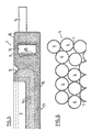
- the structure of a lower mold part 1 is shown, which consists of an edge 2 and an interior 3.
- the floor 23 of the interior can be flat as in FIG. 3 or, according to FIG. 4, may have longitudinal ribs 4 or a corrugation 24.
- the lower mold part 1 consists of a porous material 5.
- This porous material can consist, for example, of an aluminum granulate / resin mixture, wherein the aluminum granule beads 6 can have a diameter of, for example, 0.5 to 4 mm. It has proven to be advantageous to use grains of different sizes and to arrange finer grains on the inside, in the vicinity of the part to be shaped, than on the outside, as indicated schematically in FIG. 5 by three layers.
- aluminum granulate other grains can of course also be used or, for special cases, air-permeable, natural rock.
- the lower part contains 2 connections, a connection for vacuum 8 and a connection for compressed air 9, see. Fig. 1. Both connections go into an annular line 10, which consists of a metal tube with the Interior directed openings 19, which is expediently insulated with an air-permeable glass fiber mat 11. At the top there is a circumferential, for example V-shaped groove 12, into which a circumferential press ring 13 on the frame-shaped upper part 14 engages, see FIG. Fig. 7.
- the lower mold part 1 is covered with an airtight shell 15, which comprises the entire lower mold part with the exception of the inner part 3.
- the material used is a light-curing, pre-impregnated semi-finished product, a prepreg with a glass fiber roving.
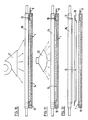
- the material web 16 is placed on the lower mold part 1 and the upper mold part 14 is closed in order to tension the web through the press ring. Then compressed air is applied through the inlet 9 so that the web part bulges.
- the arched-out web part is heated with a heating source 17, which can be a hot air blower, care being taken that the temperature in the present case does not exceed 80 ° C. A stretch of about 60% occurs. Then, see Fig.
- the vacuum source connected to the port 8 and the heated and stretched material deep-drawn by the vacuum. Since it is light-curing material, a UV light source 18 is then switched on and the molded piece is hardened, the curing time taking 40 s in the present case and depending on the material. 12, the frame 14 is then removed and the molded piece is removed from the mold under the action of compressed air.
- the scaffold plate 21 either consists of three according to FIGS. 14 and 15 or of two box-shaped parts glued together according to FIGS. 16 and 17, which are shown in FIG Form according to Figures 1 to 6 with the interiors 3 and 4 are formed.
- the same upper part 22 with the interior 3 is made for both design variants, the bottom 23 of the shape having the corrugation 24 corresponding to the upper part.
- the transverse sides each have an edge 25 which serves to accommodate the fittings 26, which are secured by screw bolts 27. After the molded and hardened piece has been removed from the mold, the edges 20 on which it was clamped and held are separated.
- the lower part 28 of the plate 21 is produced in a similar lower part than the upper part, but the surface need not be corrugated.
- the reinforcing intermediate part 29 is provided with wavy longitudinal ribs 30 and made with the mold base 4. After the edges 20 have been cut off on all three parts, these parts are glued to one another by known methods in order to produce the scaffolding plate 21. From FIG. 14 it can be seen that the side surfaces of the top and the intermediate part are aligned, while the side surfaces of the bottom part are directed in opposite directions to give a closed box.
- the scaffolding plate 32 only consists of two parts, the upper part 22 with the corrugation 24 and the intermediate or Lower part 29 with the longitudinal ribs 30.
- the part 29 with the longitudinal ribs 30 is reversed in this embodiment variant, i.e. connected to the upper part with side surfaces pointing upwards, so that there is a ribbed surface towards the outside or below.
- the edges are additionally glued and sealed with a suitable compound 31, see Fig. 18.
- a suitable compound 31 see Fig. 18.
- the scaffolding panel with the fittings provided any type of fittings can be used, if necessary by adapting the scaffolding plate parts.
- Scaffolding panels made of composite material with glass fibers which have the required stability and breaking strength as well as the same dimensions of approx. 2,500 x 600 x 50 mm as conventional wooden panels, have a weight of 14 kg compared to 28-30 kg for conventional panels .
- Such a weight saving is not only an enormous advantage for the people who have to erect a scaffold, it also reduces the freight rate, especially in the case of large buildings, by half. It should also be emphasized that the resistance to weather influences is greater than that of wood.
- the surface of the scaffolding plate can have any other suitable shape and it is also possible to roughen the surface or to provide it with a non-slip covering.
Landscapes
- Engineering & Computer Science (AREA)
- Mechanical Engineering (AREA)
- Architecture (AREA)
- Manufacturing & Machinery (AREA)
- Civil Engineering (AREA)
- Structural Engineering (AREA)
- Moulding By Coating Moulds (AREA)
- Diaphragms For Electromechanical Transducers (AREA)
- Non-Metallic Protective Coatings For Printed Circuits (AREA)
- Panels For Use In Building Construction (AREA)
- Moulds For Moulding Plastics Or The Like (AREA)
- Laminated Bodies (AREA)
- Blow-Moulding Or Thermoforming Of Plastics Or The Like (AREA)
- Making Paper Articles (AREA)
- Auxiliary Devices For And Details Of Packaging Control (AREA)
Abstract
Description
- Gerüstplatten aus Kunststoff sind, wenn überhaupt, nur sehr selten auf dem Markt anzutreffen, obwohl sie grosse Vorteile aufweisen könnten, wie beispielsweise ein wesentlich kleineres Gewicht und grösserer Widerstand gegenüber Wettereinflüssen.
- Aus der WO - 84/04940 ist ein Bauelement aus Kunststoff bekannt, das aus Glasfasergewebe und darin angeordneten Aufbauhilfskörpern besteht, wobei die Glasfasergewebebahnen Z-förmig um die Hilfskörper gelegt sind. Es hat sich gezeigt, dass diese Herstellungsweise sehr aufwendig ist und bis jetzt nicht zum Ziel geführt hat, so dass bis zum jetzigen Zeitpunkt, d.h. bis zum Anmeldetag dieser Anmeldung, die Gerüstplatten in überwiegender Mehrheit aus Holz und in geringerem Masse aus Metall bestehen, wobei beide Platten ein relativ hohes Gewicht aufweisen. Es ist demgegenüber eine erste Aufgabe der vorliegenden Erfindung eine Gerüstplatte anzugeben, die bei entsprechender, den Vorschriften genügender Stabilität, wesentlich leichter ist.
- In der Technischen Rundschau Nr. 44-86 vom 31.10.1986, S. 23ff., ist eine grosse Anzahl von Verbundwerkstoffen beschrieben, die vielfältig angewendet werden können. Für eine gewisse Anzahl von Fällen sind lichthärtende Einkomponentensysteme anwendbar, die als vorimprägnierte Halbzeuge angeboten werden. In dem genannten Artikel, der den Stand der Technik zusammenfasst, wird dieses Halbzeug verwendet, um kompliziert geformte Wickelteile herzustellen. Es ist eine weitere Aufgabe der vorliegenden Erfindung, ein Verfahren und eine Vorrichtung zur Ausführung des Verfahrens anzugeben, mit welchen es möglich ist, solche Prepregs einfach, schnell und genau zu verformen und daraus Gerüstplatten herzustellen.
- Diese Aufgaben werden mit der Gerüstplatte, mit dem Verfahren und der Vorrichtung gelöst, die in den Patentansprüchen beschrieben sind.
- Die Erfindung wird im folgenden anhand eines Ausführungsbeispiels einer Vorrichtung sowie den verschiedenen Verfahrensstufen zur Herstellung einer Gerüstplatte näher erläutert.
- Fig. 1 zeigt die erfindungsgemässe Vorrichtung von oben,
- Fig. 2 zeigt einen Längsschnitt von Fig. 1,
- Fig. 3 zeigt im grösseren Massstab einen Querschnitt der Fig. 1,
- Fig. 4 zeigt eine Ausführungsvariante zu Fig. 3,
- Fig. 5 zeigt eine Ausschnittsvergrösserung von Fig. 2,
- Fig. 6 zeigt schematisch und in vergrössertem Massstab den Aufbau der Vorrichtung gemäss Fig. 1,
- die Fig. 7 - 12 zeigen sechs Verfahrensschritte zur Herstellung einer Gerüstplatte,
- Fig. 13 zeigt eine erfindungsgemässe Gerüstplatte von oben,
- Fig. 14 zeigt einen Schnitt gemäss der Linie XIV-XIV von Fig. 13,
- Fig. 15 zeigt einen teilweisen Längsschnitt aus dem ersten Ausführungsbeispiel gemäss Fig. 13,
- Fig. 16 zeigt eine Ausführungsvariante zu Fig. 15,
- Fig. 17 zeigt die Ausführungsvariante im teilweisen Querschnitt analog zu Fig. 14, und
- Fig. 18 zeigt im vergrösserten Massstab eine abgedichtete Kante der Gerüstplatte.
- In den Fig. 1 - 6 ist der Aufbau eines Formunterteils 1 dargestellt, das aus einem Rand 2 und einem Innenraum 3 besteht. Der Boden 23 des Innenraums kann wie in Fig. 3 eben sein oder gemäss Fig. 4 Längsrippen 4 oder eine Riffelung 24 aufweisen. Wie in den Schnitten und insbesondere in Fig. 6 angedeutet, besteht das Formunterteil 1 aus einem porösen Material 5. Dieses poröse Material kann beispielsweise aus einer Aluminiumgranulat-Harzmischung bestehen, wobei die Aluminiumgranulatkügelchen 6 einen Durchmesser von beispielsweise 0,5 bis 4mm aufweisen können. Dabei hat es sich als vorteilhaft erwiesen, Körner verschiedener Grösse zu verwenden und innen, in der Nähe des zu formenden Teils, feinere Körner anzuordnen als aussen, wie dies in Fig. 5 schematisch durch drei Schichten angedeutet ist. Zur Herstellung des Formunterteils werden in einer anderen Form ein Gemisch aus Aluminiumgranulat 6 und Harz 7, etwa in einem Verhältnis von 1,5 - 1 zu 0,2 in Abhängigkeit vom Durchmesser des Aluminiumgranulats, eingegeben und erwärmt, bis die Harzschicht zu schmelzen beginnt und das Aluminiumgranulat miteinander verbindet, derart, dass wie in Fig. 6 angedeutet, Lücken entstehen, um die gewünschte Luftdurchlässigkeit zu erzielen. Anstatt Aluminiumgranulat können selbstverständlich auch andere Körner verwendet werden oder für Spezialfälle auch luftdurchlässiges, natürliches Gestein.
- Das Formunterteil enthält 2 Anschlüsse, einen Anschluss für Vakuum 8 sowie einen Anschluss für Druckluft 9, s. Fig. 1. Beide Anschlüsse gelangen in eine ringförmige Leitung 10, die aus einem Metallrohr mit nach dem Innenraum gerichteten Oeffnungen 19 besteht, welches zweckmässigerweise mit einer luftdurchlässigen Glasfasermatte 11 isoliert ist. An der Oberseite befindet sich eine umlaufende, beispielsweise V-förmige Nut 12, in die ein umlaufender Pressring 13 am rahmenförmigen Formoberteil 14 greift, s. Fig. 7. Das Formunterteil 1 ist mit einer luftdichten Hülle 15 ummantelt, die das gesamte Formunterteil mit Ausnahme des Innenteils 3 umfasst.
- Die Verwendung der Form wird im folgenden anhand der Herstellung einer Gerüstplatte gemäss den Fig. 7 - 12 und 13 - 18 erläutert. Als Material wird im vorliegenden Fall ein lichthärtendes, vorimprägniertes Halbzeug, ein Prepreg mit einem Glasfaserroving, verwendet. Die Materialbahn 16 wird auf das Formunterteil 1 gelegt und das Formoberteil 14 wird geschlossen, um die Bahn durch den Pressring zu spannen. Daraufhin wird durch den Einlass 9 Druckluft beaufschlagt, so dass sich das Bahnteil wölbt. Gleichzeitig wird das herausgewölbte Bahnteil mit einer Heizquelle 17, die ein Heissluftgebläse sein kann, erwärmt, wobei Sorge getragen wird, dass die Temperatur in vorliegendem Fall 80°C nicht übersteigt. Dabei tritt eine Streckung um etwa 60% ein. Anschliessend wird, s. Fig. 10, die Vakuumquelle an den Anschluss 8 geschaltet und das erwärmte und gestreckte Material durch das Vakuum tiefgezogen. Da es sich um lichthärtendes Material handelt, wird daraufhin eine UV-Lichtquelle 18 angeschaltet und das geformte Stück dabei gehärtet, wobei in vorliegendem Fall und abhängig vom Material, die Härtezeit 40s dauert. Anschliessend wird gemäss Fig. 12 der Rahmen 14 entfernt und das geformte Stück unter Druckluftbeaufschlagung aus der Form entnommen.
- Die Gerüstplatte 21 besteht entweder gemäss den Figuren 14 und 15 aus drei oder gemäss den Figuren 16 und 17 aus zwei kastenförmigen zusammengeklebten Teilen, die in der Form gemäss den Figuren 1 bis 6 mit den Innenräumen 3 und 4 geformt werden. Für beide Ausführungsvarianten wird das gleiche Oberteil 22 mit dem Innenraum 3 angefertigt, wobei der Boden 23 der Form die dem Oberteil entsprechende Riffelung 24 aufweist. Die Querseiten weisen je einen Rand 25 auf, der der Aufnahme der Beschläge 26 dient, die durch Schraubenbolzen 27 gesichert sind. Nach dem Herausnehmen des geformten und gehärteten Stücks aus der Form werden die Ränder 20, an denen es aufgespannt und gehalten war, abgetrennt.
- Das Unterteil 28 der Platte 21 wird in einem ähnlichen Formunterteil hergestellt wie das Oberteil, wobei jedoch die Oberfläche nicht geriffelt zu sein braucht. Das verstärkende Zwischenteil 29 ist mit wellenförmigen Längsrippen 30 versehen und mit dem Formboden 4 hergestellt. Nach dem Abschneiden der Ränder 20 an allen drei Teilen werden diese Teile nach bekannten Verfahren miteinander verklebt, um die Gerüstplatte 21 zu ergeben. Aus der Figur 14 geht hervor, dass die Seitenflächen des Ober- und des Zwischenteils gleichgerichtet sind, während die Seitenflächen des Bodenteils entgegengesetzt gerichtet sind um einen geschlossenen Kasten zu ergeben.
- In der Ausführungsvariante gemäss den Figuren 16 und 17 besteht die Gerüstplatte 32 nur noch aus zwei Teilen, dem Oberteil 22 mit der Riffelung 24 und dem Zwischen- bzw. Unterteil 29 mit den Längsrippen 30. Das Teil 29 mit den Längsrippen 30 ist jedoch in dieser Ausführungsvariante umgekehrt, d.h. mit nach oben weisenden Seitenflächen mit dem Oberteil verbunden, so dass sich nach aussen, bzw. unten, eine gerippte Oberfläche ergibt.
- Um einen vollständigen Schutz gegen Feuchtigkeit zu erzielen, werden die Kanten zusätzlich mit einer geeigneten Masse 31 verklebt und abgedichtet, siehe Fig. 18. Anschliessend wird die Gerüstplatte mit den Beschlägen versehen, wobei jede Art Beschläge verwendet werden kann, gegebenenfalls unter Anpassung der Gerüstplattenteile. Gerüstplatten aus Verbundwerkstoff mit Glasfasern, die die erforderliche Stabilität und Bruchfestigkeit sowie die gleichen Abmessungen von ca. 2′500 x 600 x 50 mm wie herkömmliche Holzplatten aufweisen, weisen ein Gewicht von 14 kg gegenüber einem solchen von 28 - 30 kg bei herkömmlichen Platten auf. Eine solche Gewichtsersparnis ist nicht nur für die Personen, die ein Gerüst aufbauen müssen von enormem Vorteil, sondern senkt auch die Frachtrate, besonders bei Grossbauten um die Hälfte. Ausserdem ist hervorzuheben, dass die Beständigkeit gegenüber Witterungseinflüssen grösser ist als beim Holz.
- Anstatt der gezeigten Riffelung kann die Oberfläche der Gerüstplatte jede andere geeignete Gestalt aufweisen und es ist auch möglich, die Oberfläche aufzurauhen oder mit einem rutschfesten Belag zu versehen.
Claims (16)
Priority Applications (6)
| Application Number | Priority Date | Filing Date | Title |
|---|---|---|---|
| EP19860810534 EP0268720B1 (de) | 1986-11-24 | 1986-11-24 | Gerüstplatte aus Kunststoff, Verfahren zu ihrer Herstellung und Vorrichtung zur Ausführung des Verfahrens |
| DE8686810534T DE3677227D1 (de) | 1986-11-24 | 1986-11-24 | Geruestplatte aus kunststoff, verfahren zu ihrer herstellung und vorrichtung zur ausfuehrung des verfahrens. |
| ES86810534T ES2019882B3 (es) | 1986-11-24 | 1986-11-24 | Placa de caballete de plastico, procedimiento para su fabricacion y dispositivo para llevar a cabo el procedimiento |
| AT86810534T ATE60395T1 (de) | 1986-11-24 | 1986-11-24 | Geruestplatte aus kunststoff, verfahren zu ihrer herstellung und vorrichtung zur ausfuehrung des verfahrens. |
| US07/122,136 US4852691A (en) | 1986-11-24 | 1987-11-17 | Scaffolding board formed from plastics materials, a method of producing same, and an apparatus for implementing the method |
| JP62295927A JPS63217066A (ja) | 1986-11-24 | 1987-11-24 | プラスチック材料から形成された足場板、足場板を製造する方法および該方法を実施する装置 |
Applications Claiming Priority (1)
| Application Number | Priority Date | Filing Date | Title |
|---|---|---|---|
| EP19860810534 EP0268720B1 (de) | 1986-11-24 | 1986-11-24 | Gerüstplatte aus Kunststoff, Verfahren zu ihrer Herstellung und Vorrichtung zur Ausführung des Verfahrens |
Publications (2)
| Publication Number | Publication Date |
|---|---|
| EP0268720A1 true EP0268720A1 (de) | 1988-06-01 |
| EP0268720B1 EP0268720B1 (de) | 1991-01-23 |
Family
ID=8196475
Family Applications (1)
| Application Number | Title | Priority Date | Filing Date |
|---|---|---|---|
| EP19860810534 Expired - Lifetime EP0268720B1 (de) | 1986-11-24 | 1986-11-24 | Gerüstplatte aus Kunststoff, Verfahren zu ihrer Herstellung und Vorrichtung zur Ausführung des Verfahrens |
Country Status (6)
| Country | Link |
|---|---|
| US (1) | US4852691A (de) |
| EP (1) | EP0268720B1 (de) |
| JP (1) | JPS63217066A (de) |
| AT (1) | ATE60395T1 (de) |
| DE (1) | DE3677227D1 (de) |
| ES (1) | ES2019882B3 (de) |
Cited By (5)
| Publication number | Priority date | Publication date | Assignee | Title |
|---|---|---|---|---|
| WO1992001131A1 (de) * | 1990-07-06 | 1992-01-23 | Josef Welser Ohg Profilier- Und Stanzwerk | Gerüstbohle und verfahren zu deren herstellung |
| EP0462481A3 (en) * | 1990-06-20 | 1992-09-16 | Tetra Alfa Holdings S.A. | Apparatus for heating plate-like parts |
| DE4318070A1 (de) * | 1993-06-01 | 1994-12-08 | Buna Gmbh | Gerüstbohle aus Kunststoff |
| DE10012685A1 (de) * | 2000-03-15 | 2001-10-04 | Layher W Vermogensverw Gmbh | Laufboden |
| CN106863789A (zh) * | 2017-03-13 | 2017-06-20 | 国家林业局北京林业机械研究所 | 一种竹塑复合材料快速成型方法与设备 |
Families Citing this family (17)
| Publication number | Priority date | Publication date | Assignee | Title |
|---|---|---|---|---|
| US5118095A (en) * | 1990-06-11 | 1992-06-02 | Flor Robert J | Adjustable exercising step |
| CA2111724A1 (en) * | 1993-12-17 | 1995-06-18 | Raymond Wayne Gillard | Scaffold system |
| US5555955A (en) * | 1994-06-17 | 1996-09-17 | Patent Construction Systems, Harsco Corporation | Combination scaffold plank |
| GB9610955D0 (en) * | 1996-05-24 | 1996-07-31 | Hercules Inc | Sizing composition |
| US6105723A (en) * | 1996-12-23 | 2000-08-22 | Harsco Corporation | Steel plank for scaffolding |
| US6431316B1 (en) | 1999-07-13 | 2002-08-13 | Timothy Benson Bothwell | Scaffold plank and method of making the same |
| US7090053B2 (en) * | 1999-07-13 | 2006-08-15 | Bothwell Enterprises, Inc. | Scaffold plank with end connector and method of making the same |
| CA2287104A1 (en) | 1999-07-19 | 2001-01-19 | Karl Hermann Werner Gregori | Decking assembly and decking kit with hold-down clip |
| US6422344B1 (en) * | 2000-09-19 | 2002-07-23 | John J. Cox | Folding step ladder |
| US6745871B2 (en) * | 2002-03-27 | 2004-06-08 | Chad D. Armstrong | Interlocking scaffold plank |
| EP1490219A2 (de) * | 2002-03-30 | 2004-12-29 | Uti Holding + Management AG | Leichte ger stplatte und verfahren zu deren herstellung |
| NO319365B1 (no) * | 2003-11-12 | 2005-07-18 | Rh Products Int As | Gulvelement for stillas |
| US9266289B2 (en) * | 2006-02-21 | 2016-02-23 | Werner Co. | Fiberglass reinforced plastic products having increased weatherability, system and method |
| US8418811B2 (en) * | 2006-02-21 | 2013-04-16 | Werner Co. | Fiberglass reinforced plastic products having increased weatherability, system and method |
| US20070289813A1 (en) * | 2006-06-07 | 2007-12-20 | Bothwell Timothy B | Scaffold plank with end connector and method of making the same |
| US20090020364A1 (en) * | 2007-07-17 | 2009-01-22 | Wolfe Iii Albert A | Scaffolding plank |
| US20130256060A1 (en) * | 2012-03-29 | 2013-10-03 | Safway Services, Llc | Scaffold Plank Structure |
Citations (7)
| Publication number | Priority date | Publication date | Assignee | Title |
|---|---|---|---|---|
| DE1559034A1 (de) * | 1965-11-09 | 1969-08-21 | Hans Meisch | Abschlagbares Arbeitsgeruest |
| DE1759177A1 (de) * | 1968-04-06 | 1972-01-27 | Eberhard Layher | Horizontales Geruestelement fuer Holz- und Metallgerueste |
| FR2340187A1 (fr) * | 1976-02-04 | 1977-09-02 | Mitsubishi Heavy Ind Ltd | Procede et appareil pour le formage d'un film en matiere plastique sur un modele a cavites profondes |
| FR2457946A1 (fr) * | 1979-06-01 | 1980-12-26 | Somefran | Element de plancher pour echafaudage |
| GB2058188A (en) * | 1979-08-14 | 1981-04-08 | Hill R T | Building Boards |
| DE3419494A1 (de) * | 1984-05-25 | 1985-11-28 | MYAC-Fleischtechnologie GmbH, 6680 Neunkirchen | Beheizbare werkzeugflaeche an einer form-, fuell- und verschliessmaschine |
| GB2167340A (en) * | 1984-10-18 | 1986-05-29 | Honda Motor Co Ltd | Vacuum mold |
Family Cites Families (8)
| Publication number | Priority date | Publication date | Assignee | Title |
|---|---|---|---|---|
| US3884328A (en) * | 1973-10-01 | 1975-05-20 | Chester I Williams | Scaffold plank |
| GB1487302A (en) * | 1975-01-10 | 1977-09-28 | Cementation Chem Ltd | Scaffold boards |
| DE2526620B2 (de) * | 1975-06-13 | 1979-04-05 | Somefran, Societe D'exploitation Des Brevets Mefran S.A., Florensac (Frankreich) | Gerüstboden |
| US4349297A (en) * | 1980-11-19 | 1982-09-14 | Misener Terrance J | Boat dock |
| US4496029A (en) * | 1983-03-30 | 1985-01-29 | Shigeharu Kuroda | Scaffold plank |
| JPS60229741A (ja) * | 1984-04-27 | 1985-11-15 | Sekisui Chem Co Ltd | 足場板用長繊維補強合成樹脂発泡体の製造方法 |
| JPS6229668A (ja) * | 1985-07-29 | 1987-02-07 | 新田物産株式会社 | 足場板 |
| US4742890A (en) * | 1987-10-22 | 1988-05-10 | Protective Plastics Limited | Work platform |
-
1986
- 1986-11-24 EP EP19860810534 patent/EP0268720B1/de not_active Expired - Lifetime
- 1986-11-24 AT AT86810534T patent/ATE60395T1/de active
- 1986-11-24 DE DE8686810534T patent/DE3677227D1/de not_active Expired - Fee Related
- 1986-11-24 ES ES86810534T patent/ES2019882B3/es not_active Expired - Lifetime
-
1987
- 1987-11-17 US US07/122,136 patent/US4852691A/en not_active Expired - Fee Related
- 1987-11-24 JP JP62295927A patent/JPS63217066A/ja active Pending
Patent Citations (7)
| Publication number | Priority date | Publication date | Assignee | Title |
|---|---|---|---|---|
| DE1559034A1 (de) * | 1965-11-09 | 1969-08-21 | Hans Meisch | Abschlagbares Arbeitsgeruest |
| DE1759177A1 (de) * | 1968-04-06 | 1972-01-27 | Eberhard Layher | Horizontales Geruestelement fuer Holz- und Metallgerueste |
| FR2340187A1 (fr) * | 1976-02-04 | 1977-09-02 | Mitsubishi Heavy Ind Ltd | Procede et appareil pour le formage d'un film en matiere plastique sur un modele a cavites profondes |
| FR2457946A1 (fr) * | 1979-06-01 | 1980-12-26 | Somefran | Element de plancher pour echafaudage |
| GB2058188A (en) * | 1979-08-14 | 1981-04-08 | Hill R T | Building Boards |
| DE3419494A1 (de) * | 1984-05-25 | 1985-11-28 | MYAC-Fleischtechnologie GmbH, 6680 Neunkirchen | Beheizbare werkzeugflaeche an einer form-, fuell- und verschliessmaschine |
| GB2167340A (en) * | 1984-10-18 | 1986-05-29 | Honda Motor Co Ltd | Vacuum mold |
Cited By (9)
| Publication number | Priority date | Publication date | Assignee | Title |
|---|---|---|---|---|
| EP0462481A3 (en) * | 1990-06-20 | 1992-09-16 | Tetra Alfa Holdings S.A. | Apparatus for heating plate-like parts |
| US5227177A (en) * | 1990-06-20 | 1993-07-13 | Tetra Alfa Holdings S.A. | Device for heating platelike parts |
| US5394603A (en) * | 1990-06-20 | 1995-03-07 | Tetra Laval Holdings & Finance S.A. | Method for heating and molding platelike parts |
| WO1992001131A1 (de) * | 1990-07-06 | 1992-01-23 | Josef Welser Ohg Profilier- Und Stanzwerk | Gerüstbohle und verfahren zu deren herstellung |
| US5443137A (en) * | 1990-07-06 | 1995-08-22 | Josef Welser Ohg Profilier- Und Stanzwerk | Scaffold board and method for making the same |
| DE4318070A1 (de) * | 1993-06-01 | 1994-12-08 | Buna Gmbh | Gerüstbohle aus Kunststoff |
| DE10012685A1 (de) * | 2000-03-15 | 2001-10-04 | Layher W Vermogensverw Gmbh | Laufboden |
| DE10012685B4 (de) * | 2000-03-15 | 2007-06-21 | Wilhelm Layher Verwaltungs-Gmbh | Verfahren zur Herstellung eines Laufbodens |
| CN106863789A (zh) * | 2017-03-13 | 2017-06-20 | 国家林业局北京林业机械研究所 | 一种竹塑复合材料快速成型方法与设备 |
Also Published As
| Publication number | Publication date |
|---|---|
| JPS63217066A (ja) | 1988-09-09 |
| ES2019882B3 (es) | 1991-07-16 |
| ATE60395T1 (de) | 1991-02-15 |
| EP0268720B1 (de) | 1991-01-23 |
| DE3677227D1 (de) | 1991-02-28 |
| US4852691A (en) | 1989-08-01 |
Similar Documents
| Publication | Publication Date | Title |
|---|---|---|
| EP0268720A1 (de) | Gerüstplatte aus Kunststoff, Verfahren zu ihrer Herstellung und Vorrichtung zur Ausführung des Verfahrens | |
| EP0010121B1 (de) | Vorgefertigte, selbsttragende Platten und Verfahren zu ihrer Herstellung | |
| DE1778021A1 (de) | Verfahren und Vorrichtung zur Herstellung von Platten,insbesondere Bauplatten,sowie die Platten selbst | |
| DE69508525T2 (de) | Verfahren zur Herstellung schichtartiger Verbundwerkstoffplatten und so hergestellte Platten | |
| DE1609695A1 (de) | Leichtbauplatte | |
| EP0156295B1 (de) | Verfahren zur Elastomerbeschichtung von Mineralwerkstoffen und nach diesem Verfahren hergestelltes Produkt | |
| DE805708C (de) | Platten, Schalen und Profile | |
| DE1949209A1 (de) | Verfahren und Vorrichtung zum Herstellen von Bauelementen | |
| EP0465719A2 (de) | Flächiger Gegenstand mit Wabenstruktur und Verfahren zu dessen Herstellung | |
| EP3237183B1 (de) | Verfahren und vorrichtung zur herstellung eines sandwichbauteils | |
| CH403285A (de) | Verfahren und Vorrichtung zur kontinuierlichen Herstellung von aus Kunstharz gebildeten Formteilen und Profilbahnen | |
| WO1981001304A1 (fr) | Corps faconne rigide, etire biaxialement, en matiere synthetique, et procede pour sa fabrication | |
| DE4431585A1 (de) | Verfahren zum Herstellen einer Verbundplatte | |
| EP1175540A1 (de) | Mehrschichtiger formkörper sowie verfahren zur herstellung eines mehrschichtigen formkörpers | |
| DE2512777A1 (de) | Feuerschutzwandbauelement | |
| EP0951389B1 (de) | Warmedämmformkörper mit umhüllung und verfahren zu deren herstellung | |
| EP0009053A1 (de) | Verfahren zur Herstellung von witterungsbeständigen Platten oder Formkörpern aus Holzfaserwerkstoffen und nach dem Verfahren hergestellte Platten oder Formkörper | |
| EP0268719A1 (de) | Tiefziehform zum Verformen von duroplastischen Verbundstoffen und Verfahren zum Betrieb der Tiefziehform | |
| DE19926417A1 (de) | Sandwichbauteil | |
| DE2056477C3 (de) | Verfahren zur Herstellung von gewölbten Körpern aus duroplastischen glasfaserverstärkten Kunststoffen | |
| EP0191892B1 (de) | Formkörper in Stützkernbauweise und Verfahren zur Herstellung desselben | |
| DE3741692C2 (de) | Verfahren zur Herstellung eines Verbundteiles sowie Verbundteil | |
| DE2613964A1 (de) | Verfahren zur herstellung von aus bahnen geschaeumten kunststoffes und kunststoffolie bestehendem schichtstoff und aus diesem schichtstoff hergestellter schichtkoerper | |
| DE2042404A1 (en) | Bend resistant panelling - with core and fibreglass matting covers all impregnated with same resin | |
| EP1095197A1 (de) | Schnellbau- und schalttafel, sowie verfahren zum zurichten einer solchen und verfahren und vorrichtung zu ihrer herstellung |
Legal Events
| Date | Code | Title | Description |
|---|---|---|---|
| PUAI | Public reference made under article 153(3) epc to a published international application that has entered the european phase |
Free format text: ORIGINAL CODE: 0009012 |
|
| AK | Designated contracting states |
Kind code of ref document: A1 Designated state(s): AT BE CH DE ES FR GB GR IT LI LU NL SE |
|
| RBV | Designated contracting states (corrected) |
Designated state(s): AT BE CH DE ES FR GB IT LI LU NL SE |
|
| 17P | Request for examination filed |
Effective date: 19881129 |
|
| 17Q | First examination report despatched |
Effective date: 19891027 |
|
| GRAA | (expected) grant |
Free format text: ORIGINAL CODE: 0009210 |
|
| AK | Designated contracting states |
Kind code of ref document: B1 Designated state(s): AT BE CH DE ES FR GB IT LI LU NL SE |
|
| REF | Corresponds to: |
Ref document number: 60395 Country of ref document: AT Date of ref document: 19910215 Kind code of ref document: T |
|
| ITF | It: translation for a ep patent filed | ||
| REF | Corresponds to: |
Ref document number: 3677227 Country of ref document: DE Date of ref document: 19910228 |
|
| GBT | Gb: translation of ep patent filed (gb section 77(6)(a)/1977) | ||
| ET | Fr: translation filed | ||
| RAP4 | Party data changed (patent owner data changed or rights of a patent transferred) |
Owner name: POLYTEX PLASTIC SA |
|
| PLBE | No opposition filed within time limit |
Free format text: ORIGINAL CODE: 0009261 |
|
| STAA | Information on the status of an ep patent application or granted ep patent |
Free format text: STATUS: NO OPPOSITION FILED WITHIN TIME LIMIT |
|
| 26N | No opposition filed | ||
| PGFP | Annual fee paid to national office [announced via postgrant information from national office to epo] |
Ref country code: LU Payment date: 19931015 Year of fee payment: 8 |
|
| PGFP | Annual fee paid to national office [announced via postgrant information from national office to epo] |
Ref country code: GB Payment date: 19931026 Year of fee payment: 8 |
|
| PGFP | Annual fee paid to national office [announced via postgrant information from national office to epo] |
Ref country code: SE Payment date: 19931027 Year of fee payment: 8 |
|
| PGFP | Annual fee paid to national office [announced via postgrant information from national office to epo] |
Ref country code: ES Payment date: 19931029 Year of fee payment: 8 |
|
| PGFP | Annual fee paid to national office [announced via postgrant information from national office to epo] |
Ref country code: DE Payment date: 19931108 Year of fee payment: 8 |
|
| PGFP | Annual fee paid to national office [announced via postgrant information from national office to epo] |
Ref country code: CH Payment date: 19931124 Year of fee payment: 8 |
|
| PGFP | Annual fee paid to national office [announced via postgrant information from national office to epo] |
Ref country code: NL Payment date: 19931130 Year of fee payment: 8 Ref country code: BE Payment date: 19931130 Year of fee payment: 8 Ref country code: AT Payment date: 19931130 Year of fee payment: 8 |
|
| EPTA | Lu: last paid annual fee | ||
| PGFP | Annual fee paid to national office [announced via postgrant information from national office to epo] |
Ref country code: FR Payment date: 19931217 Year of fee payment: 8 |
|
| PG25 | Lapsed in a contracting state [announced via postgrant information from national office to epo] |
Ref country code: LU Free format text: LAPSE BECAUSE OF NON-PAYMENT OF DUE FEES Effective date: 19941124 Ref country code: GB Effective date: 19941124 Ref country code: AT Effective date: 19941124 |
|
| PG25 | Lapsed in a contracting state [announced via postgrant information from national office to epo] |
Ref country code: SE Effective date: 19941125 Ref country code: ES Free format text: LAPSE BECAUSE OF THE APPLICANT RENOUNCES Effective date: 19941125 |
|
| PG25 | Lapsed in a contracting state [announced via postgrant information from national office to epo] |
Ref country code: LI Effective date: 19941130 Ref country code: CH Effective date: 19941130 Ref country code: BE Effective date: 19941130 |
|
| EAL | Se: european patent in force in sweden |
Ref document number: 86810534.7 |
|
| BERE | Be: lapsed |
Owner name: S.A. POLYTEX PLASTIC Effective date: 19941130 |
|
| PG25 | Lapsed in a contracting state [announced via postgrant information from national office to epo] |
Ref country code: NL Effective date: 19950601 |
|
| NLV4 | Nl: lapsed or anulled due to non-payment of the annual fee | ||
| GBPC | Gb: european patent ceased through non-payment of renewal fee |
Effective date: 19941124 |
|
| PG25 | Lapsed in a contracting state [announced via postgrant information from national office to epo] |
Ref country code: FR Effective date: 19950731 |
|
| REG | Reference to a national code |
Ref country code: CH Ref legal event code: PL |
|
| PG25 | Lapsed in a contracting state [announced via postgrant information from national office to epo] |
Ref country code: DE Effective date: 19950801 |
|
| EUG | Se: european patent has lapsed |
Ref document number: 86810534.7 |
|
| REG | Reference to a national code |
Ref country code: FR Ref legal event code: ST |
|
| REG | Reference to a national code |
Ref country code: ES Ref legal event code: FD2A Effective date: 20010402 |
|
| PG25 | Lapsed in a contracting state [announced via postgrant information from national office to epo] |
Ref country code: IT Free format text: LAPSE BECAUSE OF NON-PAYMENT OF DUE FEES;WARNING: LAPSES OF ITALIAN PATENTS WITH EFFECTIVE DATE BEFORE 2007 MAY HAVE OCCURRED AT ANY TIME BEFORE 2007. THE CORRECT EFFECTIVE DATE MAY BE DIFFERENT FROM THE ONE RECORDED. Effective date: 20051124 |