EP0268745A2 - Bandpositionseinstellung durch die Bestimmung der Begrenzung im Rückwärtslauf; Bandantriebsanordnung und -verfahren - Google Patents
Bandpositionseinstellung durch die Bestimmung der Begrenzung im Rückwärtslauf; Bandantriebsanordnung und -verfahren Download PDFInfo
- Publication number
- EP0268745A2 EP0268745A2 EP87110792A EP87110792A EP0268745A2 EP 0268745 A2 EP0268745 A2 EP 0268745A2 EP 87110792 A EP87110792 A EP 87110792A EP 87110792 A EP87110792 A EP 87110792A EP 0268745 A2 EP0268745 A2 EP 0268745A2
- Authority
- EP
- European Patent Office
- Prior art keywords
- tape
- block
- boundary
- gap
- capture
- Prior art date
- Legal status (The legal status is an assumption and is not a legal conclusion. Google has not performed a legal analysis and makes no representation as to the accuracy of the status listed.)
- Granted
Links
- 238000000034 method Methods 0.000 title claims description 45
- 230000033001 locomotion Effects 0.000 claims description 35
- 230000001965 increasing effect Effects 0.000 claims description 5
- 230000002401 inhibitory effect Effects 0.000 claims description 4
- 230000001133 acceleration Effects 0.000 claims description 2
- 230000003247 decreasing effect Effects 0.000 claims 1
- 238000001514 detection method Methods 0.000 description 16
- 230000000694 effects Effects 0.000 description 14
- 101500023488 Lithobates catesbeianus GnRH-associated peptide 1 Proteins 0.000 description 8
- 230000004907 flux Effects 0.000 description 8
- 230000006870 function Effects 0.000 description 8
- 230000007704 transition Effects 0.000 description 8
- 101500022510 Lithobates catesbeianus GnRH-associated peptide 2 Proteins 0.000 description 6
- 238000012795 verification Methods 0.000 description 5
- 238000012546 transfer Methods 0.000 description 4
- 101100282115 Candida albicans (strain SC5314 / ATCC MYA-2876) HIP1 gene Proteins 0.000 description 3
- 238000009825 accumulation Methods 0.000 description 3
- 238000010586 diagram Methods 0.000 description 3
- 101150112629 gap3 gene Proteins 0.000 description 3
- 230000007246 mechanism Effects 0.000 description 3
- 230000002159 abnormal effect Effects 0.000 description 2
- 230000003213 activating effect Effects 0.000 description 2
- 238000013459 approach Methods 0.000 description 2
- 230000002457 bidirectional effect Effects 0.000 description 2
- 238000013461 design Methods 0.000 description 2
- 230000004044 response Effects 0.000 description 2
- 230000001629 suppression Effects 0.000 description 2
- AKNNEGZIBPJZJG-MSOLQXFVSA-N (-)-noscapine Chemical compound CN1CCC2=CC=3OCOC=3C(OC)=C2[C@@H]1[C@@H]1C2=CC=C(OC)C(OC)=C2C(=O)O1 AKNNEGZIBPJZJG-MSOLQXFVSA-N 0.000 description 1
- 230000004913 activation Effects 0.000 description 1
- 230000002411 adverse Effects 0.000 description 1
- 230000005540 biological transmission Effects 0.000 description 1
- 238000012790 confirmation Methods 0.000 description 1
- 230000001186 cumulative effect Effects 0.000 description 1
- 230000002708 enhancing effect Effects 0.000 description 1
- 239000003550 marker Substances 0.000 description 1
- 238000012986 modification Methods 0.000 description 1
- 230000004048 modification Effects 0.000 description 1
- 230000008569 process Effects 0.000 description 1
- 230000001105 regulatory effect Effects 0.000 description 1
- 230000000630 rising effect Effects 0.000 description 1
- 230000035939 shock Effects 0.000 description 1
- 230000009897 systematic effect Effects 0.000 description 1
- 238000011144 upstream manufacturing Methods 0.000 description 1
Images


Classifications
-
- G—PHYSICS
- G11—INFORMATION STORAGE
- G11B—INFORMATION STORAGE BASED ON RELATIVE MOVEMENT BETWEEN RECORD CARRIER AND TRANSDUCER
- G11B15/00—Driving, starting or stopping record carriers of filamentary or web form; Driving both such record carriers and heads; Guiding such record carriers or containers therefor; Control thereof; Control of operating function
- G11B15/005—Programmed access in sequence to indexed parts of tracks of operating tapes, by driving or guiding the tape
-
- G—PHYSICS
- G11—INFORMATION STORAGE
- G11B—INFORMATION STORAGE BASED ON RELATIVE MOVEMENT BETWEEN RECORD CARRIER AND TRANSDUCER
- G11B15/00—Driving, starting or stopping record carriers of filamentary or web form; Driving both such record carriers and heads; Guiding such record carriers or containers therefor; Control thereof; Control of operating function
- G11B15/02—Control of operating function, e.g. switching from recording to reproducing
- G11B15/05—Control of operating function, e.g. switching from recording to reproducing by sensing features present on or derived from record carrier or container
- G11B15/087—Control of operating function, e.g. switching from recording to reproducing by sensing features present on or derived from record carrier or container by sensing recorded signals
-
- G—PHYSICS
- G11—INFORMATION STORAGE
- G11B—INFORMATION STORAGE BASED ON RELATIVE MOVEMENT BETWEEN RECORD CARRIER AND TRANSDUCER
- G11B15/00—Driving, starting or stopping record carriers of filamentary or web form; Driving both such record carriers and heads; Guiding such record carriers or containers therefor; Control thereof; Control of operating function
- G11B15/18—Driving; Starting; Stopping; Arrangements for control or regulation thereof
- G11B15/20—Moving record carrier backwards or forwards by finite amounts, i.e. backspacing, forward spacing
-
- G—PHYSICS
- G11—INFORMATION STORAGE
- G11B—INFORMATION STORAGE BASED ON RELATIVE MOVEMENT BETWEEN RECORD CARRIER AND TRANSDUCER
- G11B27/00—Editing; Indexing; Addressing; Timing or synchronising; Monitoring; Measuring tape travel
- G11B27/10—Indexing; Addressing; Timing or synchronising; Measuring tape travel
- G11B27/19—Indexing; Addressing; Timing or synchronising; Measuring tape travel by using information detectable on the record carrier
- G11B27/22—Means responsive to presence or absence of recorded information signals
-
- G—PHYSICS
- G11—INFORMATION STORAGE
- G11B—INFORMATION STORAGE BASED ON RELATIVE MOVEMENT BETWEEN RECORD CARRIER AND TRANSDUCER
- G11B2220/00—Record carriers by type
- G11B2220/90—Tape-like record carriers
Definitions
- the present invention relates to tape positioning in the context of tape drive systems.
- the invention has particular applicability to streaming tape drive systems using a magnetic tape medium, while providing for other applications.
- Streaming tape drive systems are designed for the rapid storage and retrieval of bulk data in conjunction with a host computer.
- data is stored in the form of a series of blocks of magnetic flux activity on a magnetic tape medium, the blocks being spaced by inter-block gaps with nominally no magnetic flux activity.
- the blocks can be written or read, seriatim , without stopping or reversing the transfer of tape across read/write heads.
- the tape After streaming is interrupted, the tape must be repositioned. This repositioning normally requires backward motion of the tape. This is clear when a block containing an error must be reread or rewritten. However, even when all previous block have been successfully written or read, backwards motion may be required since, while a streaming tape drive is ramping down to a stop, the next block to be read, or the next region to be erased and written over may have crossed the read and write heads.
- Repositioning can be effected by a drive controller which instructs a drive mechanism to stop a forward moving tape, move the tape in a backward direction, and stop the backward motion at a point appropriate for the next forward operation.
- a drive controller which instructs a drive mechanism to stop a forward moving tape, move the tape in a backward direction, and stop the backward motion at a point appropriate for the next forward operation.
- a position indicator can include a bidirectional counter which counts tallies generated by a tape speed sensor.
- the speed sensor can include a barrel which frictionally engages a tape as it is being transferred across the heads.
- the sensor can have an optically marked element which rotates with the barrel. As the element rotates, the marks can be detected by a sensor and the detections counted by the position, indicator. Normally, the counting takes into account the direction of tape transfer, e.g., counting up during forward motion and counting down during rearward motion.
- a start-stop read procedure involves reading a block and detecting its rear boundary, which takes the form of a block-to-gap transition. The value of the position indicator at this detection is then stored; this step is referred to as a position capture.
- the system can then ramp down to a stop.
- the position indicator should then indicate a value greater than the stored boundary position value. Rearward motion is began and continued until the position indicated is sufficiently less than the stored position value that a forward tape speed sufficient for reading can be achieved within the gap following the block just read. Thus, the system is ready to read the next block. This repositioning with respect to the rear boundary of a block to prepare for an operation concerning the following block is referred to as a "hitch" operation.
- a backspace operation is used generally to reread or rewrite a block.
- Such a retry is generally in response to an error detection.
- the rear boundary capture for the previous block can be used as a position reference.
- Errors in repositioning can cause the tape drive system to confuse one block for another, seriously impairing performance. Furthermore, repositioning errors impair the system's ability to handle noise in the form of flux activity within gaps and dropouts within blocks, which can impair the determination of whether a block or gap is present.
- a major source of such errors is tape slippage relative to the barrel of the speed sensor. Such slippage is most prone to occur during acceleration and deceleration of the tape, and thus especially during reversals of tape direction. Slippage errors are cumulative since the last boundary capture, so that repositioning errors are more likely for complex repositioning procedures.
- differential tape stretch Another source of error is differential tape stretch, which is routinely caused by tape tension variations as a function of tape direction.
- Differential tape stretch can cause the segment of tape corresponding to a block of data, or other information unit, to have a different length during rearward motion than it does during forward motion.
- the magnitude of the differential can correlate with the length of segment under consideration.
- position indicator errors is to limit the accuracy of repositionings. To the extent that the errors are systematic, they can be compensated for in advance, for example, by adjusting the calculated value of the point at which repositioning is to be completed. Random errors can be minimized and/or accommodated by design tolerances.
- a standardized streaming tape drive format such as group code recorded format includes in its specifications a minimum interblock gap length of 0.28 ⁇ . This figure can be used in designing the tolerances of a tape drive system that uses this format.
- a tape drive system and method provides for increased precision during repositioning by using block boundary captures made while the a is moving in a rearward direction. This generally allows the errors due to at least one tape direction reversal to be cancelled in a repositioning procedure.
- the rear boundary of a block can be captured while the tape is moving in reverse. This "reverse capture” cancels the effect of prior errors, provided they are within tolerance. Thus, when forward motion is resumed, the position error is fairly restricted to that incurred during the next reversal to forward movement, without the confounding effect of prior reversals.
- a front boundary gap can be captured while the tape is moving in reverse.
- the value of the reverse-captured front boundary can be used as the reference for repositioning, cancelling errors due to prior reversals in direction.
- a tape drive system includes means for capturing front and rear boundaries while the tape is moving forward and while it is moving backwards. These captures can be performed in two independent ways within a single system. In a gap transition approach, transitions in a signal indicating whether a block or gap is present can be used to identify block boundaries. In a boundary marker approach, conventional preambles and postambles can be read and identified in forward or reverse.
- a repositioning strategy must address the challenge of ensuring that a captured boundary belongs to the correct block. It is possible for a block to be followed by a very short block which is crossed while the system is ramping down to a stop. Without precautions, the rear boundary of the second block could be captured and mistaken for the rear boundary of the intended block.
- the rear boundary of the subject block can be captured, effectively cancelling accumulated position errors.
- the subsequent gap is then checked to confirm that its length meets the required minimum.
- the tape direction is reversed. At first, boundary capture is inhibited so that rear boundaries of any small adjacent blocks cannot be confused with the rear boundary of the subject block.
- a capture mode is activated only when the value of the position indicator represents a point which must be within the gap adjacent the rear boundary assuming any errors induced since the forward capture of the boundary of interest are within tolerance.
- the capture mode might be activated as the position indicator attains a value corresponding to the rear boundary as captured in the forward direction plus an offset representing one half the length of a minimum sized gap. This ensures that the next detection of a block boundary is the rear boundary of interest.
- the first reverse capture following the forward rear boundary capture should be the rear boundary of the subject block about which repositioning is to occur. Errors due to intervening reversal of direction are cancelled by the reverse capture of the rear boundary. In the backspace operation, errors due to differential tape stretch are cancelled by the subsequent reverse capture of the front boundary.
- error sources are essentially restricted to differential stretch over the ramp up distance and a single tape reversal, since the last rearward capture. These errors can be cancelled by the next forward-going boundary capture.
- the forward-captured front boundary position value can be used in conjunction with the subsequent forward-captured rear boundary value to calculate the length of a block.
- the length of a block can be used to inhibit capture while dropouts are traversed. In other words, when a dropout has been detected while reading a block, this dropout must not be treated as defining a front boundary during a backspace operation. Thus, during the reverse motion of a backspace operation, gap capture can be inhibited until the position indicator value indicates that the block is almost traversed, taking into account the appropriate tolerances.
- a tape drive system 100 for storing and retrieving information in connection with a host computer 99 is shown in FIG. 1.
- the tape drive system 100 includes a drive mechanism 110 for transferring a magnetic medium tape 101 across an included head assembly 112 between a supply reel 114 and a take-up reel 116. As the tape 101 moves, it engages the barrel of a speed sensor 118.
- the main function of the speed sensor is to provide a position tally for use in determining tape position.
- TRACK ACTIVITY signals in the form of electrical voltage levels as the tape is transferred across a read head of assembly 112. These electrical voltages are processed by read circuitry 120 which converts the information to DATA signals in a form intelligible to the host computer 99. The converted information is transferred to the host computer 99 through an interface buffer 130.
- information is sent from the host computer 99 through the buffer 130 for encoding by write circuitry 140 of the tape drive system 100.
- the encoded electrical data is then converted to magnetic flux activity by a write head of assembly 112. This magnetic flux activity is stored on the passing tape 101.
- the write circuitry 140 adds, to the user data from the host computer 99, system data used by the read circuitry 120 to format, check and correct information upon retrieval. Specifically, the write circuitry 140 formats user information into a series of blocks including BLOCK1, BLOCK2, and BLOCK3, separated by interblock gaps, including GAP1, GAP2, GAP3, as shown in FIGS. 3-5.
- the write head of assembly 112 is upstream of the read head so that the read circuitry 120 can also be in a verify mode in which the tape 101 is read from while it is being written to.
- the transfer of the tape 101 across the heads of assembly 112 is regulated according to DRIVE COMMAND signals from a drive controller 150 which controls the starting, stopping, speed and direction of the supply reel 114 and the take-up reel 116. For example, if the buffer becomes full during a read operation, it can flag this condition with a FULL signal to the drive controller 150. The drive controller 150 then can direct the tape drive mechanism 110 to stop the transfer of tape until the host computer 99 has had time to clear some memory in the buffer 130. A similar procedure is followed when the buffer 130 issues an EMPTY signal during a write operation.
- the drive controller 150 Before starting to read or write the next block, the drive controller 150 must manage a hitch operation to take into account ramp down and ramp up times. If during a read or verification, the read circuitry 120 detects an error requiring a retry, the system 10 must backspace over the block in which the error was detected, taking into account ramp-up and ramp-down in determining where to halt reverse motion.
- the drive controller 150 In order for the drive controller 150 to manage precise repositioning during hitch and backspace operations, it must be able to determine the current position of the heads, specifically the read head, relative to a data block of interest. Tape position and direction is determined from the quadrature POSITION TALLY output of the speed sensor 118 as input to position capture circuitry 160.
- the position capture circuitry 160 includes a bidirectional counter which increments during forward motion tallies and decrements during rearward motion tallies. The speed sensor 118 and the position capture circuitry 160 function together as a position indicator.
- the read circuitry 120 When the read circuitry 120 detects a transition from a gap to a block, its CAPTURE output to the position capture circuitry 160 triggers the storage of the current value of the counter in an incorporated register dedicated to gap-to-block position captures. Similarly, a block-to-gap detection can result in a store to a register dedicated to block-to-gap captures.
- These registers are routinely polled by the drive, controller 150 so that it maintains a record of the captured positions of current and recently read blocks. In accordance with the present invention, these captures can be made while the tape is moving in reverse, as well as while the tape is moving forward.
- the read circuitry 120 can recognize preambles and postambles to data blocks.
- block boundary captures can be confirmed.
- the postamble can be a mirror image of the preamble, so that the same circuitry can be used to confirm reverse block/gap boundary captures.
- a tape drive system could include circuitry for recognizing preambles and postambles independently in either direction.
- the read circuitry 120 includes de-skew circuitry 210, a read formatter 220, a pattern decoder 230, a block/gap filter 240, a block/gap meter 250 and a state machine 260.
- the latter four components are part of a block detect section which also includes a tape mark detector to handle end-of-file markers, a verify counter to measure the lengths of specialized non-data blocks, and a block type section which makes the final determination as to the type of block being read.
- the track activity data TA from the read head is digitized and input to the de-skew circuitry 210.
- the de-skew circuitry 210 corrects timing misalignments in parallel channels of electrical data, corresponding to the parallel tracks of flux activity, according to the format for storing information on the tape 101.
- the parallel channels are de-skewed by aligning preambles in the respective data blocks.
- both de-skewed track activity data DTA and a preamble detection signal PRE are provided by the de-skew circuitry 210.
- the PRE signal actually indicates the detection of a postamble.
- the postamble is used in the forward direction to indicate that a block is completed.
- the read formatter 220 detects the postamble as it is reading a block.
- a POST signal is provided by the read/formatter 220.
- the POST signal can be used to indicate a preamble detection.
- the pattern decoder 230 examines the de-skewed track activity signals DTA to make pattern determinations on an instantaneous basis. In other words, erasure in all tracks is used to indicate a gap, so the instantaneous block/gap pattern signal b/g ⁇ goes low. Otherwise, b/g ⁇ is high. While b/g ⁇ is high, the pattern decoder can make other pattern detections to identify tape marks, tape format identification marks, and other specialized marks for use by unillustrated components of the block detect circuitry.
- the b/g ⁇ signal is examined over time by a block/gap filter 240 to distinguish noise from actual block or gap determinations. This is done using a counter to threshold consecutive b/g ⁇ signals. The result is a block/gap determination signal B/G ⁇ .
- the B/G ⁇ signal is available to the drive controller 150 to indicate the presence of a block or a gap. This B/G ⁇ signal is also directed to a block/gap meter 250 to be measured against predetermined thresholds.
- the block/gap meter 250 includes a counter which is reset upon each transition of B/G ⁇ .
- One of the thresholds indicated in measuring a gap is the minimum standard length for an interblock gap. This threshold is used in verifying that a detected gap is an interblock gap and that it is large enough for the drive controller 150 to use in positioning operations.
- a BIG signal is provided to the drive controller 150 to indicate gap verification. Block versus gap determinations, along with other defined thresholds, are encoded and transmitted as a LENGTH signal to the state machine 260.
- the state machine 260 progresses through a network of states.
- the state at any time is a function of the previous state and received inputs.
- the inputs to the state machine include the PRE signal from the deskew circuitry 210, the POST signal from the read/formatter 220, the LENGTH signal from the meter 250, and commands CMD from the drive controller 150.
- the primary commands of interest are a start-up read command to get things moving after a reset, and a stream command to keep things going without stopping.
- the main function of the state machine is to provide a detect state output DSTATE which embodies certain sequences of inputs. This DSTATE output can then be used to resolve ambiguous boundary or block-type determinations in favor of probable sequences and against improbable sequences. By implementing the state machine in hardware, these resolutions can be made in real time, enhancing the accuracy of the block detect circuitry. Some of the state transitions indicate errors, which are flagged at the EFLAG output.
- the illustrated state machine 260 has eighteen states, one of which is a reset state. The remaining states are divided into three sets, each corresponding to a phase in a read cycle. These phases are "pre-detect”, “read” and "gap check”.
- the read phase generally occurs while a block is being read or verified. This phase can be exited when a postamble is indicated by a POST input, or when a timeout such as might be caused by a gap of length at least that of a minimum interblock gap.
- the transition is then to a state in the gap check phase.
- the present gap may or may not need to be verified.
- the system can get trapped in a block overrun state of this phase if a block is entered before a stream command is received. In this case, the exit is via a reset command. Otherwise, a stream command causes a transition to a gap verify state of the pre-detect phase.
- the pre-detect phase can also be entered from the reset state upon either a stream command or a start-up command.
- the major application of the DSTATE output is to suppress a P1CLK signal and a P2CLK signal from the filter 240.
- the P1CLK signal and P2CLK signal constitute the CAPTURE signals shown in FIG. 1.
- the P1CLK signal is used to trigger gap-to-block boundary captures, while the P2CLK is used to trigger block-to-gap boundary captures.
- P1CLK and P2CLK trigger position value captures by the position capture circuitry 160 to the respective registers. While P1CLK is suppressed, gap-to-block boundary detections cannot result in captures. While P2CLK is suppressed, block-to-gap boundary detections cannot result in a capture. Thus, the state machine governs when block/gap boundaries can be captured.
- a gap-to-block boundary capture temporarily inhibits subsequent gap-to-block boundary captures
- a block-to-gap boundary capture temporarily inhibits subsequent block-to-gap captures, until a gap at least as long as a minimum interblock gap is measured. This prevents small dropouts and drop-ins from being captured, wiping out legitimate boundary captures before the drive controller has a chance to store them.
- the drive controller has time to request, along line REQ, one or more position captures, as selected along lines ADDR.
- the requested capture values are forwarded to the drive controller 150 along bus CAPVAL.
- a major feature of these read circuitry 120 is that it can function in either tape direction.
- preambles look like post ambles, and vice-a-versa.
- P1CLK detects gap-to-block boundaries in either direction; in other words, P1CLK captures front boundaries of blocks during forward tape motion, and rear boundaries of blocks during reverse tape motion.
- P2CLK detects block-to-gap boundaries in either direction; so again the roles of front and rear boundaries are reversed according to tape direction.
- the drive controller 150 governs tape direction, it can properly interpret the information it receives from the read circuitry 120 and the position capture circuitry 160. This system 100 can thus employ reverse as well as forward position tape captures in performing positioning procedures and operations.
- FIG. 3 A start-stop read procedure incorporating a hitch operation in accordance with the present invention is illustrated in FIG. 3.
- the forward motion of the tape 101 is to the left.
- the representation below is of the read head motion relative to the tape, the relative forward motion of the head being to the right.
- the tape 101 is magnetic media tape with a series of encoded blocks of data, including blocks BLOCK1, BLOCK2, and BLOCK3, stored thereon in the form of flux reversals.
- the blocks are separated by interblock gaps including gaps GAP1, GAP2 and GAP3. These blocks and gaps define front and rear boundaries for the blocks, including front boundaries FB12, and FB23, and rear boundaries RB11, RB22 and RB33.
- start-stop read procedure The purpose of the start-stop read procedure is to permit the reading of blocks one at a time, with the time between the readings of successive blocks being greater than that available under a streaming read.
- a start stop read could be used when the buffer 130 to the host computer 99 is full so that streaming retrieval of information cannot be managed.
- the illustrated start-stop read procedure is shown comprising three segments, a BLOCK2 read segment SEG31, a hitch segment SEG32 and a BLOCK3 read segment SEG33.
- the procedure begins with a ramp-up from a position 311. Sufficient speed for reading is achieved by position 312 which is in front of GAP1, so that read and detect functions are available as the rear boundary RB11 of BLOCK1 is crossed and GAP1 is entered. At position 313, near the middle of GAP1, a capture mode is activated. In other words, P1CLK and P2CLK are allowed to follow B/G ⁇ .
- a gap-to-block capture is made at position 314 so that the front boundary FB12 of BLOCK2 is available as a reference position. That the captured value represents the front of a data block rather than noise or a specialized mark can be confirmed by the detection of a preamble.
- This confirmation is performed by the state machine 260 using the PRE input. In other words, the state machine 260 enters different states according to whether a capture is confirmed or not. Upon a confirmed capture, P1CLK is suppressed, inhibiting further gap-to-block captures.
- the contents of the data block are decoded for transmission to the host computer 99.
- the next block-to-gap detection at 315 results in the capture of the rear boundary RB22 of BLOCK2.
- the POST input to the state machine 260 can be used to confirm that the capture was of a legitimate block boundary.
- GAP2 is then measured to verify that its length is at least the predetermined minimum length for an interblock gap. This having been confirmed at or before position 316 at the front boundary FB23 of BLOCK3, the tape is ramped down to a stop at position 317.
- a position value represented at position 319 is calculated by adding a value corresponding to half a minimum gap length to the reference value corresponding to the previously captured rear boundary RB22 of BLOCK2.
- the tape is moved in a reverse direction, ramping up to speed by position 318.
- Position 318 need not be a boundary, but should be behind position 319.
- the capture mode is activated so that the next detection at position 320 is a recapture of the rear boundary RB22 of BLOCK2.
- the position value need not be the same as that stored when this boundary RB22 was captured going forward, since the tape may have slipped relative to the barrel of the speed sensor 118 during the reversal of tape direction. However, any errors induced by such slippage are cancelled by the rearward capture of RB22 at position 320.
- the value corresponding to the capture at position 320 is used as the final reference position for the hitch operation.
- the tape is ramped down to a stop at position 321.
- forward motion of the tape is resumed with operational speed being attained at position 322.
- Position 323 is the position attained when the value in the position indicator equals the last captured value corresponding to RB22 plus a tolerance offset, in this case one half a minimum gap length.
- the next boundary captured is the front boundary FB23 of BLOCK3 at position 324.
- BLOCK3 can be read until its rear boundary RB33 is captured at position 325.
- GAP3 is verified by position 326, and the tape stopped at position 327.
- Positions 321-327, with respect to BLOCK3, correspond to positions 311-317, with respect to BLOCK2.
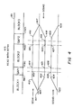
- FIG. 4 A read with retry procedure incorporating a backspace operation, in accordance with the present invention, is illustrated in FIG. 4.
- This procedure involves reading BLOCK2 during a forward segment SEG41, backspacing over BLOCK2 during a reverse segment SEG42, and then rereading BLOCK2 during a forward segment SEG43.
- This procedure could be used when the read circuitry detects an error which cannot be corrected in- stream.
- the first read segment SEG41 is the same as read segment SEG31 in the hitch operation of FIG. 3.
- the start is at position 411
- operational speed is attained at position 412
- the capture mode is enabled at position 413
- the front boundary FB12 is captured at position 414, at which point the block read begins.
- Rear boundary RB22 is captured at 415, and the GAP2 verified by position 416.
- a backspace command issued while or before the tape is stopped at position 417 initiates the backspace operation shown as segment SEG42.
- the backspace operation begins like the hitch operation.
- the tape ramps up to speed in reverse direction from position 417 to position 418.
- the capture mode is activated when, at position 419, the position indicator attains a value equal to the value at the forward-going capture of the rear boundary RB22 at position 415 plus a value representing a tolerance offset.
- Rear boundary RB22 is captured at position 420.
- GAP1 is verified in reverse by position 422, and then the tape is ramped down to a stop at position 423.
- the verification can be omitted, since verification of GAP1 has already been performed in the forward direction, and the effects of differential tape stretch can be estimated and offset mathematically.
- the stop position 423 would still have to permit ramping up to speed prior to the attainment of the next point at which the capture mode is to be activated.
- a read operation represented by segment SEG43 is executed.
- the tape ramps up to speed by position 424 from stop position 423.
- position 425 when the position indicator value equals the captured position value from front boundary FB12 position capture at position 421 less a tolerance offset representing about one half a minimum gap length, the capture mode is activated.
- the remainder of the read operation of SEG43 replicates the read operation of SEG41.
- the front boundary FB12 of BLOCK2 is captured again in the forward direction at position 426, the block reread, the rear boundary RB22 captured at position 427, GAP2 verified by position 428, and the tape ramped down to a stop at position 429.
- the block-to-gap capture mode and the gap-to-block capture mode are switched on and off. For example, while the block-to-gap capture mode is inhibited, a detected block-to-gap boundary will not be stored. This switching is used to avoid false captures. The most common false captures involve confusing one block for another block. For example, while ramping down after reading a block, another block can be entered and even traversed before a stop is executed. By inhibiting captures until a position value guaranteed to be within the gap adjacent the block of interest, captures do not reflect the boundaries of an unintended block.
- captures are inhibited during ramp downs and ramp ups.
- the capture modes are not activated until the position indicator value represents that a point within the adjacent gap is guaranteed as long as any positioning errors are within tolerances.
- This guaranteed position value is calculated to be the last captured value offset by one half a minimum gap length.
- the direction of the offset is opposed to the direction of tape movement, since the objective is to recapture the last captured boundary.
- the offset can be a fraction other than one half a minimum gap length.
- the gap-to-block capture mode is generally inactivated until a gap is verified. Likewise, once a block-to-gap capture is made, the block-to-gap capture mode is inactivated until a gap is verified. This tactic avoids confusion as to which block is present and reduces vulnerability to noise.
- the block-to-gap capture mode is activated at the same point as the gap-to-block capture mode, in the illustrated start-stop read and read with retry procedures of FIGS 3 and 4.
- the block-to-gap capture mode can be activated at a later point, such as upon the recapture of the next gap-to-block boundary, i.e., as the gap-to-block capture mode is inhibited.
- a third activation point for the block-to-gap capture mode is used in the procedure, represented in FIG. 5, applied to the abnormal case of a read of a block with a full width dropout D45.
- the block-to-gap capture mode is not activated until the boundary to be captured is approached so that the intervening dropout does not result in a capture.
- the read operation begins as before, with read operation at SEG51 starting at position 511, ramping up to speed by 512, activating the capture mode at position 513, capturing front boundary FB12 at position 514 and beginning the read of BLOCK2.
- the first dropout boundary DB24 is captured at position 515.
- the second dropout boundary DB52 is detected at position 516, terminating gap verification. Since the dropout D45 is not verified as an interblock gap, the gap-to-block capture mode is not reactivated. Under these conditions, the block-to-gap capture mode remains activated. That an error condition exists is confirmed by the fact that no postamble is detected.
- the backspace operation depicted as SEG52 begins by ramping up to speed in the reverse direction by position 520, activating the gap-to-block capture mode at position 521 in response to the value of the position indicator, and recapturing RB22 at position 522.
- the block-to-gap capture mode is not activated along with the gap-to-block capture mode, nor upon recapture of RB22. Instead, the block-to-gap capture mode is activated at position 523 when the position indicator attains a calculated value.
- This value can be calculated as follows.
- the forward capture value of FB12 taken at position 514 is subtracted from the forward capture value of RB22 taken at position 517. This yields a value representing the length of BLOCK2.
- This length value is subtracted from the rearward capture value of RB22 taken at position 522.
- the difference is the position expected for FB12 in the absence of differential stretch errors. Added to this expected position is a tolerance, which can be a function of the calculated length, since differential stretch errors tend to correlate with block length.
- the block-to-gap capture mode is activated. Usually, this will result in the dropout being ignored and the next capture being of the desired front boundary FB12 at position 524. This last capture is then available for use as the reference position for the next procedure once GAP1 is verified by position 525 and the tape stopped at position 526.
- This full-width dropout procedure is one example of many procedures that can be adapted according to the situation as determined by an overall tape positioning strategy.
- the strategy can take into account abnormal situations as detected and indicated by error flags, missing preambles and postambles, unverified gaps, etc.
Landscapes
- Digital Magnetic Recording (AREA)
- Signal Processing For Digital Recording And Reproducing (AREA)
- Adjustment Of The Magnetic Head Position Track Following On Tapes (AREA)
Applications Claiming Priority (2)
| Application Number | Priority Date | Filing Date | Title |
|---|---|---|---|
| US933650 | 1986-11-21 | ||
| US06/933,650 US4821129A (en) | 1986-11-21 | 1986-11-21 | Tape positioning using reverse boundary capture: tape drive system and method |
Publications (3)
| Publication Number | Publication Date |
|---|---|
| EP0268745A2 true EP0268745A2 (de) | 1988-06-01 |
| EP0268745A3 EP0268745A3 (de) | 1991-05-29 |
| EP0268745B1 EP0268745B1 (de) | 1994-08-31 |
Family
ID=25464302
Family Applications (1)
| Application Number | Title | Priority Date | Filing Date |
|---|---|---|---|
| EP87110792A Expired - Lifetime EP0268745B1 (de) | 1986-11-21 | 1987-07-24 | Bandpositionseinstellung durch die Bestimmung der Begrenzung im Rückwärtslauf; Bandantriebsanordnung und -verfahren |
Country Status (5)
| Country | Link |
|---|---|
| US (1) | US4821129A (de) |
| EP (1) | EP0268745B1 (de) |
| JP (1) | JP2690089B2 (de) |
| CA (1) | CA1326539C (de) |
| DE (1) | DE3750461T2 (de) |
Cited By (3)
| Publication number | Priority date | Publication date | Assignee | Title |
|---|---|---|---|---|
| CN1067170C (zh) * | 1991-09-17 | 2001-06-13 | 皇家菲利浦电子有限公司 | 获得带型磁记录载体的装置及对该载体重放的装置 |
| EP1659581A1 (de) * | 2004-11-10 | 2006-05-24 | Certance LLC | Anordnung und Verfahren zur Steuerung ders Zwischenspeicher-Unterlaufs eines Bandlaufwerks |
| EP1672628A1 (de) * | 2004-11-10 | 2006-06-21 | Certance LLC | Anordnung und Verfahren zur Steuerung des Zwischenspeicher-Unterlaufs eines Bandlaufwerks |
Families Citing this family (27)
| Publication number | Priority date | Publication date | Assignee | Title |
|---|---|---|---|---|
| US5218640A (en) * | 1988-02-03 | 1993-06-08 | Sharp Kabushiki Kaisha | Voice recording and reproducing apparatus |
| US4991036A (en) * | 1988-06-08 | 1991-02-05 | Storage Technology Corporation | Moving data storage media mode/direction change optimization |
| JPH081683B2 (ja) * | 1988-08-15 | 1996-01-10 | シャープ株式会社 | 磁気テープを用いる再生方式 |
| EP0468112B1 (de) * | 1990-07-25 | 1995-09-06 | Hewlett-Packard Limited | Einrichtung zum Auslesen digitaler Daten von einem Band |
| US5264972A (en) * | 1991-10-15 | 1993-11-23 | Tandberg Data A/S | Method and apparatus for maintaining tape tension in a belt-driven tape cartridge |
| US5349481A (en) * | 1993-06-10 | 1994-09-20 | Exabyte Corporation | Apparatus and method for distorted track data recovery by rewinding and re-reading the tape at a slower than nominal speed |
| JPH0836807A (ja) * | 1994-07-27 | 1996-02-06 | Fujitsu Ltd | 磁気テープ装置 |
| US5995306A (en) * | 1996-01-26 | 1999-11-30 | Exabyte Corporation | Handling defective frames on hard sectored magnetic tape |
| US6307701B1 (en) | 1998-10-20 | 2001-10-23 | Ecrix Corporation | Variable speed recording method and apparatus for a magnetic tape drive |
| US6367047B1 (en) | 1998-10-20 | 2002-04-02 | Ecrix | Multi-level error detection and correction technique for data storage recording device |
| US6246551B1 (en) | 1998-10-20 | 2001-06-12 | Ecrix Corporation | Overscan helical scan head for non-tracking tape subsystems reading at up to 1X speed and methods for simulation of same |
| US6381706B1 (en) | 1998-10-20 | 2002-04-30 | Ecrix Corporation | Fine granularity rewrite method and apparatus for data storage device |
| US6308298B1 (en) | 1998-11-16 | 2001-10-23 | Ecrix Corporation | Method of reacquiring clock synchronization on a non-tracking helical scan tape device |
| US6367048B1 (en) | 1998-11-16 | 2002-04-02 | Mcauliffe Richard | Method and apparatus for logically rejecting previously recorded track residue from magnetic media |
| US6603618B1 (en) | 1998-11-16 | 2003-08-05 | Exabyte Corporation | Method and system for monitoring and adjusting tape position using control data packets |
| US6421805B1 (en) | 1998-11-16 | 2002-07-16 | Exabyte Corporation | Rogue packet detection and correction method for data storage device |
| JP4464491B2 (ja) * | 1999-08-17 | 2010-05-19 | 富士通株式会社 | 磁気テープ装置 |
| US6364234B1 (en) | 2000-03-10 | 2002-04-02 | Michael Donald Langiano | Tape loop/slack prevention method and apparatus for tape drive |
| US6624960B1 (en) | 2000-03-10 | 2003-09-23 | Exabyte Corporation | Current sensing drum/cleaning wheel positioning method and apparatus for magnetic storage system |
| US9129614B2 (en) | 2013-05-01 | 2015-09-08 | International Business Machines Corporation | Magnetic head having canted arrays |
| US9449628B2 (en) | 2013-05-01 | 2016-09-20 | International Business Machines Corporation | Quasi-statically oriented, bi-directional tape recording head |
| US9208809B2 (en) | 2013-05-01 | 2015-12-08 | International Business Machines Corporation | Magnetic head and system having offset arrays |
| US8810957B1 (en) | 2013-09-05 | 2014-08-19 | International Business Machines Corporation | Quasi-statically tilted head having dilated transducer pitch |
| US9214164B2 (en) | 2013-09-16 | 2015-12-15 | International Business Machines Corporation | Miniskirt tape head having quasi-statically tilted transducer arrays |
| US9218838B2 (en) | 2013-12-12 | 2015-12-22 | International Business Machines Corporation | Quasi-statically tilted head having offset reader/writer transducer pairs |
| US9007712B1 (en) | 2013-12-16 | 2015-04-14 | International Business Machines Corporation | Backward compatible head for quasi-static tilted reading and/or recording |
| US9117470B1 (en) | 2014-07-17 | 2015-08-25 | International Business Machines Corporation | Write delay to de-skew data in read while write function for tape storage devices |
Family Cites Families (11)
| Publication number | Priority date | Publication date | Assignee | Title |
|---|---|---|---|---|
| JPS5012284B1 (de) * | 1970-05-08 | 1975-05-10 | ||
| US3938105A (en) * | 1974-06-24 | 1976-02-10 | Honeywell Information Systems Inc. | Sequentially encoded data structures that support bidirectional scanning |
| JPS598894B2 (ja) * | 1975-09-25 | 1984-02-28 | キヤノン株式会社 | 記録媒体制御方式 |
| JPS6023410B2 (ja) * | 1979-05-24 | 1985-06-07 | 株式会社東芝 | デ−タ間部検出回路 |
| JPS6341624Y2 (de) * | 1980-08-04 | 1988-11-01 | ||
| JPH0115002Y2 (de) * | 1980-09-06 | 1989-05-02 | ||
| US4553180A (en) * | 1981-02-12 | 1985-11-12 | Pioneer Electronic Corporation | Recording start position setting device for use in a tape recorder |
| US4551774A (en) * | 1981-03-02 | 1985-11-05 | Pioneer Electronic Corporation | Method for selecting desired piece of information recorded in magnetic tape mounted in magnetic tape recorder and/or reproducer |
| GB2096381B (en) * | 1981-04-03 | 1985-03-20 | Pioneer Electronic Corp | Device for detecting a non-recorded segment on magnetic tape |
| JPH0792951B2 (ja) * | 1984-06-05 | 1995-10-09 | 富士通テン株式会社 | 早送り頭出し制御方法 |
| JPS61253658A (ja) * | 1985-03-30 | 1986-11-11 | Fujitsu Ltd | 磁気テ−プ装置のストリ−ミングモ−ド制御方式 |
-
1986
- 1986-11-21 US US06/933,650 patent/US4821129A/en not_active Expired - Lifetime
-
1987
- 1987-07-24 DE DE3750461T patent/DE3750461T2/de not_active Expired - Lifetime
- 1987-07-24 EP EP87110792A patent/EP0268745B1/de not_active Expired - Lifetime
- 1987-11-19 CA CA000552230A patent/CA1326539C/en not_active Expired - Lifetime
- 1987-11-20 JP JP62293877A patent/JP2690089B2/ja not_active Expired - Lifetime
Cited By (5)
| Publication number | Priority date | Publication date | Assignee | Title |
|---|---|---|---|---|
| CN1067170C (zh) * | 1991-09-17 | 2001-06-13 | 皇家菲利浦电子有限公司 | 获得带型磁记录载体的装置及对该载体重放的装置 |
| EP1659581A1 (de) * | 2004-11-10 | 2006-05-24 | Certance LLC | Anordnung und Verfahren zur Steuerung ders Zwischenspeicher-Unterlaufs eines Bandlaufwerks |
| EP1672628A1 (de) * | 2004-11-10 | 2006-06-21 | Certance LLC | Anordnung und Verfahren zur Steuerung des Zwischenspeicher-Unterlaufs eines Bandlaufwerks |
| US7154695B2 (en) | 2004-11-10 | 2006-12-26 | Certance, Llc | System and method for controlling the speed of a tape drive |
| US7190544B2 (en) | 2004-11-10 | 2007-03-13 | Certance Llc | System and method for tape drive under run control |
Also Published As
| Publication number | Publication date |
|---|---|
| CA1326539C (en) | 1994-01-25 |
| JP2690089B2 (ja) | 1997-12-10 |
| DE3750461T2 (de) | 1995-04-20 |
| EP0268745A3 (de) | 1991-05-29 |
| JPS63171462A (ja) | 1988-07-15 |
| DE3750461D1 (de) | 1994-10-06 |
| EP0268745B1 (de) | 1994-08-31 |
| US4821129A (en) | 1989-04-11 |
Similar Documents
| Publication | Publication Date | Title |
|---|---|---|
| US4821129A (en) | Tape positioning using reverse boundary capture: tape drive system and method | |
| KR100359539B1 (ko) | 매체 상에 사전기록된 타이밍 기반 서보 패턴으로 변조된데이터를 검출하는 검출기 및 그 검출방법 | |
| US6580581B1 (en) | Recovery of lateral position of a servo system with respect to longitudinal servo bands of a magnetic tape | |
| US6532128B1 (en) | Data set to recording media registration and synchronization | |
| JP2001524730A (ja) | テープドライブにおけるギャップポジショニングを最適化するシステム | |
| EP0263929B1 (de) | Bandantriebsverfahren mit Bandstellenfangschaltung | |
| US5268802A (en) | Reading non-standard tapes on tape drives | |
| US5475542A (en) | Method and apparatus for improving inter-block gap length tolerance and locate accuracy for write appends | |
| EP0597707A2 (de) | Magnetbandaufnahme-/Wiedergabegerät | |
| US4737868A (en) | Repositioner for streaming magnetic tape drive apparatus | |
| US5287229A (en) | Method of avoiding accidental overwriting on magnetic tape | |
| JPH0652622B2 (ja) | ブロックパターン検出回路装置 | |
| US6198588B1 (en) | Data Storage | |
| JPH07281836A (ja) | データ転送方法 | |
| JP2669382B2 (ja) | 磁気テープ装置 | |
| JP3969265B2 (ja) | 磁気テープ装置及びその制御方法 | |
| JPS5951044B2 (ja) | 磁気テ−プ制御方式 | |
| JPS60187956A (ja) | 磁気テ−プ装置 | |
| JP2565529Y2 (ja) | 磁気テープ装置 | |
| JPS6155134B2 (de) | ||
| JPH01319103A (ja) | 磁気テープ制御装置 | |
| JPH04125837A (ja) | 磁気テープの終端検出機構 | |
| KR20010070328A (ko) | D-vhs 리코더용 탐색 모드 | |
| JPH01319104A (ja) | 磁気テープ制御装置 | |
| JPS6117056B2 (de) |
Legal Events
| Date | Code | Title | Description |
|---|---|---|---|
| PUAI | Public reference made under article 153(3) epc to a published international application that has entered the european phase |
Free format text: ORIGINAL CODE: 0009012 |
|
| AK | Designated contracting states |
Kind code of ref document: A2 Designated state(s): DE FR GB |
|
| PUAL | Search report despatched |
Free format text: ORIGINAL CODE: 0009013 |
|
| AK | Designated contracting states |
Kind code of ref document: A3 Designated state(s): DE FR GB |
|
| 17P | Request for examination filed |
Effective date: 19911029 |
|
| 17Q | First examination report despatched |
Effective date: 19920401 |
|
| GRAA | (expected) grant |
Free format text: ORIGINAL CODE: 0009210 |
|
| AK | Designated contracting states |
Kind code of ref document: B1 Designated state(s): DE FR GB |
|
| REF | Corresponds to: |
Ref document number: 3750461 Country of ref document: DE Date of ref document: 19941006 |
|
| ET | Fr: translation filed | ||
| PLBE | No opposition filed within time limit |
Free format text: ORIGINAL CODE: 0009261 |
|
| STAA | Information on the status of an ep patent application or granted ep patent |
Free format text: STATUS: NO OPPOSITION FILED WITHIN TIME LIMIT |
|
| 26N | No opposition filed | ||
| REG | Reference to a national code |
Ref country code: GB Ref legal event code: 732E |
|
| REG | Reference to a national code |
Ref country code: FR Ref legal event code: TP |
|
| REG | Reference to a national code |
Ref country code: GB Ref legal event code: IF02 |
|
| PGFP | Annual fee paid to national office [announced via postgrant information from national office to epo] |
Ref country code: FR Payment date: 20060717 Year of fee payment: 20 |
|
| PGFP | Annual fee paid to national office [announced via postgrant information from national office to epo] |
Ref country code: GB Payment date: 20060726 Year of fee payment: 20 |
|
| PGFP | Annual fee paid to national office [announced via postgrant information from national office to epo] |
Ref country code: DE Payment date: 20060831 Year of fee payment: 20 |
|
| REG | Reference to a national code |
Ref country code: GB Ref legal event code: PE20 |
|
| PG25 | Lapsed in a contracting state [announced via postgrant information from national office to epo] |
Ref country code: GB Free format text: LAPSE BECAUSE OF EXPIRATION OF PROTECTION Effective date: 20070723 |