EP0269780A1 - Dispositif de transmission de la position d'un élément de commande actionnable par le conducteur d'un véhicule - Google Patents
Dispositif de transmission de la position d'un élément de commande actionnable par le conducteur d'un véhicule Download PDFInfo
- Publication number
- EP0269780A1 EP0269780A1 EP87103646A EP87103646A EP0269780A1 EP 0269780 A1 EP0269780 A1 EP 0269780A1 EP 87103646 A EP87103646 A EP 87103646A EP 87103646 A EP87103646 A EP 87103646A EP 0269780 A1 EP0269780 A1 EP 0269780A1
- Authority
- EP
- European Patent Office
- Prior art keywords
- actuator
- lever
- control element
- clutch
- transmission
- Prior art date
- Legal status (The legal status is an assumption and is not a legal conclusion. Google has not performed a legal analysis and makes no representation as to the accuracy of the status listed.)
- Granted
Links
Images


Classifications
-
- F—MECHANICAL ENGINEERING; LIGHTING; HEATING; WEAPONS; BLASTING
- F02—COMBUSTION ENGINES; HOT-GAS OR COMBUSTION-PRODUCT ENGINE PLANTS
- F02D—CONTROLLING COMBUSTION ENGINES
- F02D11/00—Arrangements for, or adaptations to, non-automatic engine control initiation means, e.g. operator initiated
- F02D11/06—Arrangements for, or adaptations to, non-automatic engine control initiation means, e.g. operator initiated characterised by non-mechanical control linkages, e.g. fluid control linkages or by control linkages with power drive or assistance
- F02D11/10—Arrangements for, or adaptations to, non-automatic engine control initiation means, e.g. operator initiated characterised by non-mechanical control linkages, e.g. fluid control linkages or by control linkages with power drive or assistance of the electric type
- F02D11/107—Safety-related aspects
-
- B—PERFORMING OPERATIONS; TRANSPORTING
- B60—VEHICLES IN GENERAL
- B60K—ARRANGEMENT OR MOUNTING OF PROPULSION UNITS OR OF TRANSMISSIONS IN VEHICLES; ARRANGEMENT OR MOUNTING OF PLURAL DIVERSE PRIME-MOVERS IN VEHICLES; AUXILIARY DRIVES FOR VEHICLES; INSTRUMENTATION OR DASHBOARDS FOR VEHICLES; ARRANGEMENTS IN CONNECTION WITH COOLING, AIR INTAKE, GAS EXHAUST OR FUEL SUPPLY OF PROPULSION UNITS IN VEHICLES
- B60K26/00—Arrangement or mounting of propulsion-unit control devices in vehicles
- B60K26/04—Arrangement or mounting of propulsion-unit control devices in vehicles of means connecting initiating means or elements to propulsion unit
Definitions
- the invention relates to a device for transmitting the position of a control element which can be actuated by a vehicle driver according to the preamble of claim 1.
- the position of the control element ie usually the accelerator pedal position
- the position of the control element is normally transmitted to the throttle valve of a carburetor or the control rod of an injection pump electrically via the setpoint generator coupled to the accelerator pedal and electrical transmission means which, in addition to lines, an electronic controller or an electronic one Include control unit on the electrical actuator (EP-Al-0l2373l).
- the actuator is in turn mechanically coupled to the throttle valve or control rod, which form the actual actuator, in a positive and non-positive manner.
- At least one mechanical safety transmission element is effective in parallel with the electrical transmission means arranged between the control element of the setpoint generator or the setpoint generator itself and the actuator, in such a way that the normal transmission function of the safety transmission element is moved forcelessly by the control element, but in the event of a malfunction of the electrical transmission means the transmission of the control element position on the actuator.
- the at least one safety transmission element can consist of an emergency drive linkage or a Bowden cable.
- the actuator In order to prevent the engine speed from accelerating unintentionally in the event of a defect, the actuator is biased into its idling position by a return spring.
- the mechanical safety transmission element can be arranged on the actuator in the direction of adjustment to be freely movable by a predetermined amount or play, which is smaller than the maximum adjustment path.
- the safety transmission element has a so-called compensating element, which essentially consists of two parts which are adjustable relative to one another and an overtravel spring, wherein one of the two parts is connected to the actuator and the other to the setpoint generator or the control element, so in particular if the setpoint generator is defective but the electronic controller is still working, the actuator and the actuator can be moved towards the idle position, even though the safety transmission element has already produced a positive coupling between the control element and the actuator after exceeding the lots.
- the spring force of the overtravel spring is greater than that of the return spring.
- the control element by operating the control element in full throttle direction, maneuverable driving can take place if one of the electrical elements or parts has failed so that the return spring would move the actuator into the idle position.
- the safety transmission element is not only loaded with the force of the return spring, but also with friction and / or adhesive forces of the actuator and the coupling means connecting the actuator to the actuator. If the actuator blocks, the actuator can no longer be operated with the mechanical safety transmission element. Emergency operation is no longer possible. If the actuator is close to full throttle in this situation, the fuel supply or the ignition can be switched off by a known safety system in order to avoid dangers from uncontrolled driving, but it is accepted that the vehicle stops, which means that in unfavorable traffic situations, the vehicle and its occupants may in turn be at risk.
- the present invention is therefore based on the object of ensuring the safety of a device for transmitting the position of a control which can be actuated by a vehicle driver elements and to ensure in particular emergency driving properties of the vehicle even in the event of unfavorable malfunctions in which the actuator can no longer be actuated.
- the mechanical safety transmission element should also be relieved in these special malfunctions.
- the further developed facility should distinguish itself through high operational safety and the possibility of a reliable function control.
- the invention is based on the fact that from the previously largely equivalent possibilities to arrange the safety transmission element on the actuator or the actuator, the arrangement on the actuator is selected such that a controllable clutch is arranged between the actuator and the actuator and that the clutch in the event of a fault is opened automatically.
- the maximum position of the control lever in the direction of the full throttle position is in emergency driving mode limited by the lots.
- the limit of the lots is formed by the edge of the cutout on the transmission lever at which one end of the overtravel spring comes to rest. Due to the limited maximum position in emergency operation, the driver is alerted to the accident in a safety-increasing manner.
- the device for transmitting the position of the control element with emergency driving properties can be checked in a little complicated manner, for example before starting. This is important because the emergency driving feature is only rarely activated during vehicle operation, but should then function reliably.
- the test possibility is based on the fact that the controlled clutch according to claim 7 can be opened by an arbitrarily actuated test signal generator.
- the test signal can consist in particular in that the clutch is de-energized according to claim 9, so that it is operated in the same way as in the event of a fault in the failed electrical system. While the clutch is opened for testing, the rest of the device can be subjected to further input signals, and the reaction of the actuator to these input signals can be evaluated.
- the first test case consists of checking the safety transmission means between the control element and the actuator element.
- the second test case which is also carried out when the controllable clutch is open, specifies a defined operating state by the electrical control signal on the actuator, for example a specific load position (full throttle), a specific one Speed, thrust detection and the like. It is then checked whether the internal combustion engine nevertheless assumes or maintains an operating state that is not determined by the position of the actuator.
- the engine when the actuator is in full throttle position, the engine must not be cranked up.
- an electrically controlled clutch is advantageously used as the controlled clutch between the actuator and the actuator in many applications since it can directly receive electrical control signals.
- An electromagnetically operated snap-in connection is particularly suitable as a controlled coupling between the actuator and actuator.
- a positive and non-positive connection is established between the actuator and the actuator by electromagnetic actuation of the latching connection, these two elements assuming a predetermined relative position to one another.
- a pneumatic cylinder with piston can be arranged between the actuator and the actuator, which can be actuated by means of compressed or suction air.
- the pneumatic cylinder can be released via a controlled valve, so that the piston can move relative to the cylinder and thus the actuator relative to the actuator.
- the fault signal actuating the controlled clutch can be generated automatically by an intelligent fault detection device which detects, for example, that the reported actuator position deviates significantly from the position that the actuator should have assumed based on the control signals.
- the controlled clutch is arranged according to claim l0 between the actuator and an actuator, on which the return spring engages. This creates a further precondition for the fact that emergency operation can be started when the controllable clutch is disengaged by the restoring force being overcome by the safety transmission element.
- the device has the features of claim 11.
- the fact that the transmission lever and the actuator lever can be rotated relative to one another, and that the overtravel spring rests on both sides in a direction of relative rotation only on the actuator lever and its shoulder, a freewheel is formed.
- This relieves the load on the safety transmission element when, for example, the control element - the accelerator pedal - is in the idle position in undisturbed operation, while the driving speed is controlled automatically by the electronic controller and the actuator.
- the safety transmission element is also force-free in normal operation if the driver electrically adjusts the control element by actuating the control element, but following it via the electronics and the electrical actuator.
- the slack between one end of the overtravel spring and an edge on the cutout of the transmission lever can also have an effect if the edge is moved towards the end of the overtravel spring counter to the direction of rotation in which the freewheel takes effect. which rests on the shoulder of the actuator lever.
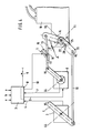
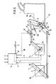
- a control element which can be actuated by a vehicle and which can represent an accelerator pedal or a lever connected to an accelerator pedal is designated by 1.
- the control element is connected to an electrical setpoint generator 2, which emits an electrical signal corresponding to the position of the control element 1 to an electronic controller 3.
- "LL" indicates the idle position of the control element, while the full load position is abbreviated to "VL".
- Fig. L shows the situation of the Setup at full load or full throttle position of the control element.
- the abbreviations "LL” and VL are also used to identify the location of the other components of the facility.
- An electrical control signal is fed from an output 5 of the controller into an electrical control element 6, which can essentially consist, for example, of an electric motor and a transmission. Feedback from the actuator via an input 7 of the actuator position.
- the controller also comprises a part 8 which is indicated by a broken line and which, in conjunction with a contact 9 which can be actuated by the driver, functions as a test signal generator and in conjunction with the input 7 as an error detection device.
- This device is discussed below in connection with FIGS. 4 and 5.
- an electrical output l0 leads to an electromagnetic actuating element, not shown, of a controlled clutch ll, which is designed as a latching connection.
- the locking connection lies in the course of an actuator frame with the actuator rods l2 and l3, which is a mechanical connection between the electrical actuator and an actuator lever l4 can produce.
- the controlled clutch 11 has a catch l5, which engages electromagnetically actuated in a groove l6 in a force-fitting and form-fitting manner or is removed from this groove when the actuating element is de-energized.
- the actuator lever loaded by a return spring l7 is used in the present example to adjust the control rod of an injection pump l8.
- the throttle valve of a carburetor can be actuated as an actuator instead of the control rod of the injection pump.
- the device for automatically maintaining an emergency driving characteristic essentially consists of an emergency driving linkage l9 as a mechanical safety transmission means between the control element l and the actuator lever 14.
- the emergency drive linkage does not act directly on the actuator lever, but on a transmission lever 20, which is rotatably mounted about an axis 2l, and also rotatable relative to the actuator lever l4, which can be adjusted about the same axis 2l.
- the transmission lever 20 can act on the actuator lever 14 only via one end 22 of an overtravel spring 23.
- the overtravel spring 23, which is essentially cylindrical in shape and is arranged coaxially to the axis 2l, can bear with the end 22 against an extension 24 of the actuator lever 14, which can be seen better from FIG. 2, for example.
- the end 22 can also come to rest against an edge 25 of a cutout 26 which is formed from the transmission lever.
- slack The angle between the edge 25 and the dash-dotted line through the point of contact of the end 22 of the overtravel spring at the Approach 26 when the leading edges of the approach and transfer lever are in register is referred to as slack.
- freewheeling The angle by which the transmission lever can be moved further away from the end 22 of the overtravel spring to the idle position is defined as freewheeling.
- a second end 27 of the overtravel spring is constantly in contact with the front edge of the actuator lever 14. A torque can be transmitted between the ends 22 and 27 of the overtravel spring which exceeds the torque which is exerted on the actuator lever 14 by the return spring 17.
- the position of the actuator lever is thus determined by the actuator 6 when the controlled clutch 11 is closed, which actuator receives an electrical control signal from the controller 3.
- the position of the control element 3 is thus transmitted electrically to the actuator.
- the electrical transmission is based on the principle of run-on control.
- a feedback signal which indicates the actuator position, is fed into the input 7 of the controller 3.
- an error detection device in the controller determines that the actuator is functioning properly. For this reason, the controllable clutch 11 receives a signal, for example a voltage, via the electrical output l0 of the error detection device, which keeps the clutch in the closed state.
- the emergency drive linkage l9 which acts on the control element, is actuated, as always, in such a way that it could cause an adjustment on the actuator l4 which is the same as the adjustment of the actuator lever l4 caused by the actuator 6.
- the operation of the emergency drive has an effect not on the actuator lever l4.
- the emergency drive linkage cannot transmit a positive connection to the actuating lever in this operating case, since the transmission lever 20 is either moved in a direction of rotation in the region of the lots formed by the cutout 26, so that the end 22 of the overtravel spring 23 does not come to rest against the edge 25 or but the transmission lever 20 is moved further away in the other direction of rotation from the end 22 of the overtravel spring in the region of the freewheel.
- a slight offset between the emergency drive linkage l9 and the actuator rods l2, l3 cannot therefore have an effect; rather, in this case too, the emergency drive linkage is moved without force when the control element is actuated.
- a normal operating situation is also shown, namely an automatic control, for example, the speed of the internal combustion engine or the driving speed of the vehicle by the electronic controller 3, while the driver and the control element actuated by him should not be adjusted the actuator lever.
- the controllable clutch 11 is also closed as a result of the corresponding signal from the output l0 of the error detection device 8.
- the control element 1 is in the idle position or at least in a position that corresponds to a lower throughput of the fuel-air mixture than it corresponds to the electrical actuator signal at the output 5 of controller 3 corresponds.
- the actuator lever is further regulated in comparison to the setpoint generator position and the position of the emergency drive linkage l9. This is done without introducing a force on the emergency drive linkage via the transmission lever 20, since the extension 24 of the actuator lever is moved away from the transmission lever.
- an adjustment of the parts is shown in a likewise normal operating case, in which the position of the actuator is automatically reduced, ie is driven in the direction of a lower throughput of the fuel-air mixture than it corresponds to the position of the control element.
- This operating case can be a limiting function, which is exercised, for example, when the controller 3 acting as a limiter reaches a maximum speed or maximum speed.
- the controllable clutch 11 is also kept closed in this normal operating case.
- the actuator 6 moves the actuator lever 14 in FIG.
- the actuator can perform this rotation of the actuator lever - assisted by the return spring l7 - by overcoming the moment exerted by the overtravel spring on the actuator lever when the end 22 of the overtravel spring bears against the edge 25 of the transmission lever 20.
- the emergency drive linkage l9 is loaded with a force which corresponds to the moment initiated by the overtravel spring on the transmission lever 20.
- the emergency drive linkage l9 which, as always, brings about a position of the transmission lever 20 corresponding to the position of the control element.
- the edge 22 on the cutout 26 of the transmission lever 20 comes into contact with the end 22 of the overtravel spring resting on the shoulder 24 as soon as the slack has been exceeded by the relative movement between the transmission lever and the actuator lever.
- the actuator lever can be rotated further into a position that regulates the internal combustion engine, since the overtravel spring can overcome the restoring force of the return spring 17 and the movement of the actuator lever as a result of the open controllable clutch 11 is no longer inhibited. Accordingly, the emergency drive linkage l9 is essentially only loaded by the restoring force.
- Fig. 4 it is indicated that the maximum position which the actuator lever l4 can assume in emergency driving mode remains behind the full-load position by an angle, which corresponds to the lots.
- the vehicle driver is also made aware of the emergency driving situation and is encouraged not to use the maximum possible performance of the internal combustion engine in this accident, but to go to a workshop.
- FIG. 5 shows the setting of the device when it is checked whether the automatic emergency running property is guaranteed.
- the contact 9 is opened and in the test signal device 8 - which is shown together with the error detection device 8 - a test signal is generated which corresponds to a fault.
- the actuating element, not shown, of the controllable clutch 11 is de-energized and de-energized and opens the clutch as in the event of a fault. It is then determined whether, as shown in FIG. 5, the actuator lever can be rotated between the maximum position for emergency operation by operating the control element.
- the decoupling function of the controllable clutch 11 can be checked with the contact 9 still open in that a defined operating state, the load position, the speed or the thrust detection is specified by corresponding signals at the inputs v, n, s of the controller 3 and is determined whether despite the open clutch changes the operating state of the internal combustion engine.
- This detection can be carried out automatically by a detection device, not shown, which, for example, determines deviations in the engine speed from a predetermined value.
- a particular advantage of the device is that the powerless running of the emergency driving device means that its function cannot become inoperable through long-term rest.
Landscapes
- Engineering & Computer Science (AREA)
- Chemical & Material Sciences (AREA)
- Combustion & Propulsion (AREA)
- Mechanical Engineering (AREA)
- General Engineering & Computer Science (AREA)
- Transportation (AREA)
- Control Of Throttle Valves Provided In The Intake System Or In The Exhaust System (AREA)
- Control Of Vehicle Engines Or Engines For Specific Uses (AREA)
- Auxiliary Drives, Propulsion Controls, And Safety Devices (AREA)
Applications Claiming Priority (2)
| Application Number | Priority Date | Filing Date | Title |
|---|---|---|---|
| DE3641275 | 1986-12-03 | ||
| DE19863641275 DE3641275A1 (de) | 1986-12-03 | 1986-12-03 | Einrichtung zur uebertragung der position eines durch einen fahrzeugfuehrer betaetigbaren steuerelements |
Publications (2)
| Publication Number | Publication Date |
|---|---|
| EP0269780A1 true EP0269780A1 (fr) | 1988-06-08 |
| EP0269780B1 EP0269780B1 (fr) | 1991-09-18 |
Family
ID=6315351
Family Applications (1)
| Application Number | Title | Priority Date | Filing Date |
|---|---|---|---|
| EP87103646A Expired - Lifetime EP0269780B1 (fr) | 1986-12-03 | 1987-03-13 | Dispositif de transmission de la position d'un élément de commande actionnable par le conducteur d'un véhicule |
Country Status (5)
| Country | Link |
|---|---|
| US (1) | US4785781A (fr) |
| EP (1) | EP0269780B1 (fr) |
| JP (1) | JPS63145132A (fr) |
| BR (1) | BR8705309A (fr) |
| DE (2) | DE3641275A1 (fr) |
Cited By (7)
| Publication number | Priority date | Publication date | Assignee | Title |
|---|---|---|---|---|
| FR2630164A1 (fr) * | 1988-04-19 | 1989-10-20 | Pierburg Gmbh | Regulateur pour le papillon du carburateur de moteurs a combustion interne |
| DE9000598U1 (de) * | 1990-01-20 | 1990-09-20 | Rathor Ag, Appenzell | Tellerventil für Druckbehälter, insbesondere zum Ausbringen von Treibmittel und Schaumbildner |
| EP0402521A1 (fr) * | 1989-06-10 | 1990-12-19 | VDO Adolf Schindling AG | Dispositif de réglage de charge |
| EP0412237A1 (fr) * | 1989-08-10 | 1991-02-13 | Audi Ag | Papillon |
| WO1991002660A1 (fr) * | 1989-08-22 | 1991-03-07 | Robert Bosch Gmbh | Dispositif pour la transmission d'une position de reglage d'un element de commande |
| WO1991002661A1 (fr) * | 1989-08-22 | 1991-03-07 | Robert Bosch Gmbh | Dispositif pour la transmission d'une position de reglage d'un element de commande |
| EP0377875B1 (fr) * | 1989-01-10 | 1994-03-16 | Mannesmann VDO AG | Dispositif de réglage de charge |
Families Citing this family (8)
| Publication number | Priority date | Publication date | Assignee | Title |
|---|---|---|---|---|
| DE3722633A1 (de) * | 1987-07-09 | 1989-01-19 | Vdo Schindling | Elektrisches gaspedal |
| US5314665A (en) * | 1987-07-27 | 1994-05-24 | Nissan Motor Co., Ltd. | Catalytic converter |
| US4940109A (en) * | 1989-07-18 | 1990-07-10 | Eaton Corporation | Split arm throttle cable intervention device |
| DE3934739A1 (de) * | 1989-10-18 | 1991-04-25 | Bosch Gmbh Robert | Vorrichtung i mit einem stellmotor zum eingriff in eine uebertragungseinrichtung |
| DE4129960C2 (de) * | 1991-09-10 | 2000-11-16 | Hella Kg Hueck & Co | Einrichtung zum Einstellen der Fahrgeschwindigkeit eines Kraftfahrzeuges |
| DE10102217B4 (de) * | 2001-01-19 | 2009-07-30 | Bayerische Motoren Werke Aktiengesellschaft | Vorrichtung und Verfahren zur Schubabschaltung |
| DE102011003430B3 (de) * | 2011-02-01 | 2012-05-31 | Continental Automotive Gmbh | Verfahren und Vorrichtung zum Überprüfen einer Steuereinrichtung |
| CN103196469B (zh) * | 2013-03-27 | 2015-08-12 | 福州大学 | 一种双燃料发动机油门开度检测装置及其安装方法 |
Citations (2)
| Publication number | Priority date | Publication date | Assignee | Title |
|---|---|---|---|---|
| GB2144179A (en) * | 1983-07-22 | 1985-02-27 | Westfaelische Metall Industrie | Motor vehicle speed control |
| GB2157367A (en) * | 1984-04-12 | 1985-10-23 | Daimler Benz Ag | Device for influencing the fuel delivery of an injection pump |
Family Cites Families (17)
| Publication number | Priority date | Publication date | Assignee | Title |
|---|---|---|---|---|
| US2077555A (en) * | 1932-01-28 | 1937-04-20 | Samuel G Frantz | Speed control device |
| US2111284A (en) * | 1936-03-23 | 1938-03-15 | Girl Christian | Speed control device |
| US3528523A (en) * | 1965-02-08 | 1970-09-15 | Robert H Thorner | Automotive speed control system |
| US3379187A (en) * | 1966-05-05 | 1968-04-23 | Roy J. Armbrust | Diesel safety control apparatus |
| US3704635A (en) * | 1971-06-01 | 1972-12-05 | Phillip V Eshelman | Throttle return spring redundancy system |
| US3699943A (en) * | 1971-06-07 | 1972-10-24 | Philip V Eshelman | Throttle return spring redundancy system |
| US4019475A (en) * | 1974-06-06 | 1977-04-26 | Chrysler Corporation | Automobile acceleration control for fuel economy |
| US3888219A (en) * | 1974-06-10 | 1975-06-10 | Ford Motor Co | Throttle linkage including an overspeed protective device |
| SE434932B (sv) * | 1977-03-30 | 1984-08-27 | Vdo Schindling | Anordning for reglering av ett motorfordons korhastighet |
| JPS5833239Y2 (ja) * | 1977-06-25 | 1983-07-25 | 株式会社ボッシュオートモーティブ システム | デイ−ゼルエンジンのスト−ル防止装置 |
| US4458645A (en) * | 1978-11-06 | 1984-07-10 | Schwartzman Everett H | Force actuated latching device and high pressure system |
| JPS5820948A (ja) * | 1981-07-29 | 1983-02-07 | Mikuni Kogyo Co Ltd | 内燃機関の燃料供給装置 |
| JPS59153945A (ja) * | 1983-02-21 | 1984-09-01 | Nissan Motor Co Ltd | スロツトルバルブ制御装置 |
| JPS6049235U (ja) * | 1983-09-12 | 1985-04-06 | 愛三工業株式会社 | 内燃機関のスロットル制御装置 |
| JPS60240835A (ja) * | 1984-05-12 | 1985-11-29 | Nissan Motor Co Ltd | 内燃機関の吸気量制御装置 |
| JP2503389B2 (ja) * | 1985-05-27 | 1996-06-05 | 日本電装株式会社 | スロットルバルブの駆動装置 |
| US4727837A (en) * | 1987-04-30 | 1988-03-01 | Sturdy Corporation | Engine governor with emergency throttle limiter |
-
1986
- 1986-12-03 DE DE19863641275 patent/DE3641275A1/de not_active Withdrawn
-
1987
- 1987-03-13 EP EP87103646A patent/EP0269780B1/fr not_active Expired - Lifetime
- 1987-03-13 DE DE87103646T patent/DE3773135D1/de not_active Expired - Lifetime
- 1987-03-17 JP JP62060249A patent/JPS63145132A/ja active Pending
- 1987-10-07 BR BR8705309A patent/BR8705309A/pt not_active IP Right Cessation
- 1987-12-03 US US07/128,463 patent/US4785781A/en not_active Expired - Fee Related
Patent Citations (2)
| Publication number | Priority date | Publication date | Assignee | Title |
|---|---|---|---|---|
| GB2144179A (en) * | 1983-07-22 | 1985-02-27 | Westfaelische Metall Industrie | Motor vehicle speed control |
| GB2157367A (en) * | 1984-04-12 | 1985-10-23 | Daimler Benz Ag | Device for influencing the fuel delivery of an injection pump |
Non-Patent Citations (2)
| Title |
|---|
| PATENT ABSTRACTS OF JAPAN, Band 10, Nr. 109 (M-472)[216], 23. April 1986; & JP - A - 60 240 835 (NISSAN) 29.11.1985 * |
| PATENT ABSTRACTS OF JAPAN, Band 9, Nr. 3 (M-349)[1726], 9. Januar 1985; & JP - A - 59 153 945 (NISSAN) 01.09.1984 * |
Cited By (7)
| Publication number | Priority date | Publication date | Assignee | Title |
|---|---|---|---|---|
| FR2630164A1 (fr) * | 1988-04-19 | 1989-10-20 | Pierburg Gmbh | Regulateur pour le papillon du carburateur de moteurs a combustion interne |
| EP0377875B1 (fr) * | 1989-01-10 | 1994-03-16 | Mannesmann VDO AG | Dispositif de réglage de charge |
| EP0402521A1 (fr) * | 1989-06-10 | 1990-12-19 | VDO Adolf Schindling AG | Dispositif de réglage de charge |
| EP0412237A1 (fr) * | 1989-08-10 | 1991-02-13 | Audi Ag | Papillon |
| WO1991002660A1 (fr) * | 1989-08-22 | 1991-03-07 | Robert Bosch Gmbh | Dispositif pour la transmission d'une position de reglage d'un element de commande |
| WO1991002661A1 (fr) * | 1989-08-22 | 1991-03-07 | Robert Bosch Gmbh | Dispositif pour la transmission d'une position de reglage d'un element de commande |
| DE9000598U1 (de) * | 1990-01-20 | 1990-09-20 | Rathor Ag, Appenzell | Tellerventil für Druckbehälter, insbesondere zum Ausbringen von Treibmittel und Schaumbildner |
Also Published As
| Publication number | Publication date |
|---|---|
| DE3773135D1 (en) | 1991-10-24 |
| US4785781A (en) | 1988-11-22 |
| BR8705309A (pt) | 1988-07-19 |
| DE3641275A1 (de) | 1988-06-16 |
| JPS63145132A (ja) | 1988-06-17 |
| EP0269780B1 (fr) | 1991-09-18 |
Similar Documents
| Publication | Publication Date | Title |
|---|---|---|
| EP0269780B1 (fr) | Dispositif de transmission de la position d'un élément de commande actionnable par le conducteur d'un véhicule | |
| EP0413081A1 (fr) | Dispositif de réglage de charge | |
| EP0377875B1 (fr) | Dispositif de réglage de charge | |
| EP0412237B1 (fr) | Papillon | |
| EP0413082A1 (fr) | Dispositif de réglage de charge | |
| EP0123731B1 (fr) | Dispositif pour transmettre la position d'un élément de commande | |
| EP0483448B1 (fr) | Dispositif de réglage de charge | |
| EP0427097A1 (fr) | Soupape d'étranglement pour moteur à combustion interne | |
| DE3326460C2 (fr) | ||
| DE3813047A1 (de) | Verstelleinrichtung fuer die drosselklappe einer gemischbildungseinrichtung fuer brennkraftmaschinen | |
| EP0378737B1 (fr) | Dispositif de réglage de la charge | |
| DE3711779A1 (de) | Drosselklappe | |
| EP0378736B1 (fr) | Dispositif de réglage de la charge | |
| EP0456904B1 (fr) | Dispositif de réglage de la puissance | |
| DE3628538C2 (de) | Anordnung für ein Kraftfahrzeug zum Eingriff in die Verbindung zwischen einem Bedienorgan und einem die Leistung der Brennkraftmaschine des Kraftfahrzeugs bestimmenden Steuerorgan | |
| EP0306641A1 (fr) | Commande électrique de papillon pour moteur à combustion interne | |
| EP0421047B1 (fr) | Dispositif de réglage de charge | |
| EP0300153B1 (fr) | Dispositif de réglage de charge | |
| DE3809910A1 (de) | Vorrichtung zur leistungsbeeinflussung von brennkraftmaschinen | |
| EP0478884B1 (fr) | Dispositif de réglage de charge | |
| DE4342754A1 (de) | Vorrichtung zum Steuern der Leistung einer Antriebsmaschine | |
| EP0488016A2 (fr) | Dispositif de commande de la puissance d'un moteur à combustion interne notamment pour véhicule automobile | |
| DE69314199T2 (de) | Drosselklappenstelleinrichtung | |
| EP0455882A2 (fr) | Dispositif de réglage pour un papillon des gaz | |
| EP0454971B1 (fr) | Positionneur de butée pour papillon des gaz |
Legal Events
| Date | Code | Title | Description |
|---|---|---|---|
| PUAI | Public reference made under article 153(3) epc to a published international application that has entered the european phase |
Free format text: ORIGINAL CODE: 0009012 |
|
| AK | Designated contracting states |
Kind code of ref document: A1 Designated state(s): DE FR GB NL SE |
|
| 17P | Request for examination filed |
Effective date: 19880629 |
|
| 17Q | First examination report despatched |
Effective date: 19900608 |
|
| GRAA | (expected) grant |
Free format text: ORIGINAL CODE: 0009210 |
|
| AK | Designated contracting states |
Kind code of ref document: B1 Designated state(s): DE FR GB NL SE |
|
| ET | Fr: translation filed | ||
| REF | Corresponds to: |
Ref document number: 3773135 Country of ref document: DE Date of ref document: 19911024 |
|
| GBT | Gb: translation of ep patent filed (gb section 77(6)(a)/1977) | ||
| PG25 | Lapsed in a contracting state [announced via postgrant information from national office to epo] |
Ref country code: SE Effective date: 19920314 |
|
| PLBE | No opposition filed within time limit |
Free format text: ORIGINAL CODE: 0009261 |
|
| STAA | Information on the status of an ep patent application or granted ep patent |
Free format text: STATUS: NO OPPOSITION FILED WITHIN TIME LIMIT |
|
| 26N | No opposition filed | ||
| PG25 | Lapsed in a contracting state [announced via postgrant information from national office to epo] |
Ref country code: NL Effective date: 19921001 |
|
| NLV4 | Nl: lapsed or anulled due to non-payment of the annual fee | ||
| EUG | Se: european patent has lapsed |
Ref document number: 87103646.3 Effective date: 19921005 |
|
| PGFP | Annual fee paid to national office [announced via postgrant information from national office to epo] |
Ref country code: GB Payment date: 19950213 Year of fee payment: 9 |
|
| PGFP | Annual fee paid to national office [announced via postgrant information from national office to epo] |
Ref country code: FR Payment date: 19950217 Year of fee payment: 9 |
|
| PGFP | Annual fee paid to national office [announced via postgrant information from national office to epo] |
Ref country code: DE Payment date: 19960216 Year of fee payment: 10 |
|
| PG25 | Lapsed in a contracting state [announced via postgrant information from national office to epo] |
Ref country code: GB Effective date: 19960313 |
|
| GBPC | Gb: european patent ceased through non-payment of renewal fee |
Effective date: 19960313 |
|
| PG25 | Lapsed in a contracting state [announced via postgrant information from national office to epo] |
Ref country code: FR Effective date: 19961129 |
|
| REG | Reference to a national code |
Ref country code: FR Ref legal event code: ST |
|
| PG25 | Lapsed in a contracting state [announced via postgrant information from national office to epo] |
Ref country code: DE Effective date: 19971202 |