EP0270420A1 - Verfahren und Vorrichtung zum Verfertigen einer Verpackung aus zwei mit einander verbundenen Teilen, insbesondere für Eier - Google Patents
Verfahren und Vorrichtung zum Verfertigen einer Verpackung aus zwei mit einander verbundenen Teilen, insbesondere für Eier Download PDFInfo
- Publication number
- EP0270420A1 EP0270420A1 EP87402521A EP87402521A EP0270420A1 EP 0270420 A1 EP0270420 A1 EP 0270420A1 EP 87402521 A EP87402521 A EP 87402521A EP 87402521 A EP87402521 A EP 87402521A EP 0270420 A1 EP0270420 A1 EP 0270420A1
- Authority
- EP
- European Patent Office
- Prior art keywords
- plate
- edges
- flaps
- upper face
- main wall
- Prior art date
- Legal status (The legal status is an assumption and is not a legal conclusion. Google has not performed a legal analysis and makes no representation as to the accuracy of the status listed.)
- Withdrawn
Links
Images




Classifications
-
- B—PERFORMING OPERATIONS; TRANSPORTING
- B31—MAKING ARTICLES OF PAPER, CARDBOARD OR MATERIAL WORKED IN A MANNER ANALOGOUS TO PAPER; WORKING PAPER, CARDBOARD OR MATERIAL WORKED IN A MANNER ANALOGOUS TO PAPER
- B31B—MAKING CONTAINERS OF PAPER, CARDBOARD OR MATERIAL WORKED IN A MANNER ANALOGOUS TO PAPER
- B31B50/00—Making rigid or semi-rigid containers, e.g. boxes or cartons
- B31B50/74—Auxiliary operations
- B31B50/81—Forming or attaching accessories, e.g. opening devices, closures or tear strings
-
- B—PERFORMING OPERATIONS; TRANSPORTING
- B31—MAKING ARTICLES OF PAPER, CARDBOARD OR MATERIAL WORKED IN A MANNER ANALOGOUS TO PAPER; WORKING PAPER, CARDBOARD OR MATERIAL WORKED IN A MANNER ANALOGOUS TO PAPER
- B31B—MAKING CONTAINERS OF PAPER, CARDBOARD OR MATERIAL WORKED IN A MANNER ANALOGOUS TO PAPER
- B31B2105/00—Rigid or semi-rigid containers made by assembling separate sheets, blanks or webs
-
- B—PERFORMING OPERATIONS; TRANSPORTING
- B31—MAKING ARTICLES OF PAPER, CARDBOARD OR MATERIAL WORKED IN A MANNER ANALOGOUS TO PAPER; WORKING PAPER, CARDBOARD OR MATERIAL WORKED IN A MANNER ANALOGOUS TO PAPER
- B31B—MAKING CONTAINERS OF PAPER, CARDBOARD OR MATERIAL WORKED IN A MANNER ANALOGOUS TO PAPER
- B31B2120/00—Construction of rigid or semi-rigid containers
- B31B2120/20—Construction of rigid or semi-rigid containers provided with two or more compartments
-
- B—PERFORMING OPERATIONS; TRANSPORTING
- B31—MAKING ARTICLES OF PAPER, CARDBOARD OR MATERIAL WORKED IN A MANNER ANALOGOUS TO PAPER; WORKING PAPER, CARDBOARD OR MATERIAL WORKED IN A MANNER ANALOGOUS TO PAPER
- B31B—MAKING CONTAINERS OF PAPER, CARDBOARD OR MATERIAL WORKED IN A MANNER ANALOGOUS TO PAPER
- B31B2241/00—Making bags or boxes intended for a specific use
- B31B2241/002—Making egg cartons
Definitions
- the invention relates to a method and a machine for producing a packaging in two parts rigidly associated with one another in opposite directions, in particular a packaging for eggs.
- This package has an upper tray and a lower bottom.
- the tray in thermoformed plastic, has hollow cells open upwards, distributed in rows and columns on an upper face and, on the same side as these edge cells which, when the packaging is in its normal position use, that is to say horizontally flat, are arranged at least substantially vertically and directed downwards.
- the bottom made of cardboard, has foldable flaps normally arranged at least substantially vertically and directed upwards from a main wall. The edges and the corresponding flaps are associated with one another, in particular rigidly by bonding.
- the tray has a tormented shape, suitable for receiving the contents to be packaged (eggs). Its intrinsic resistance is quite low. In particular, the edges can sink if a perpendicular force is exerted on them.
- the tray fulfills a function of receptacle for the content and the bottom a holding or stiffening function.
- the flaps can be pivoted around their fold line.
- the packaging has the required strength and rigidity.
- the internal space between the tray and the bottom is closed and inaccessible from the outside. This results in a serious problem for the realization of the packaging: the inaccessibility of this space does not allow the accommodation of a counterpart allowing a transverse force of application for the association of the edges and the flaps, which would be all the more necessary as the edges have, in themselves, a fairly low inherent resistance.
- Um packaging of this general type is described in documents EP 0089 and EP 0188 731.
- This type of packaging can optionally include a cover.
- the invention therefore aims to solve the problem of the reciprocal rigid association of the tray and of a bottom of a two-part packaging, in particular by rigid association of the foldable edges and flaps belonging respectively to the tray and to the bottom more especially in the case on the one hand, the edges have, in themselves, a fairly low resistance and on the other hand, the internal space formed by the plate and the bottom is inaccessible from the outside.
- Another object of the invention is to produce such packaging industrially, with a high rate, a limited cost, excellent operational safety, excellent quality.
- a method of manufacturing packaging for eggs is already known (document FR 2 480 178). However, this method does not allow the production of a packaging of the type described above.
- a method and a device are also known for obtaining a packaging in two parts: a cardboard bottom with flaps and a sheet of thermoformed plastic (document FR 2 411 701). Thermoforming and the association of the thermoformed sheet with the base previously placed in the thermoforming mold are carried out simultaneously.
- This method and this device are of complex implementation, do not allow high rates, present the risk of variable quality.
- the box according to GB 952 930 is such that the edges of the box are directed upwards (and not downwards according to the invention), the plate being lower (and not upper according to the invention) since forming the bottom of the box, the tray being flat and devoid of cells therefore unsuitable for packaging eggs, the envelope having as sole function the aesthetic character (and not the strength and stiffening according to the invention), bottom flaps being double, on the outside face of the edges of the plate and on the inside face, which supposes a peripherally hollow plate (whereas according to the invention, there is only one flap outside of the song, the inside of the songs being peripherally inaccessible from above).
- the document GB 2 059 868 also describes a machine for producing a box of the same general type as that concerned by the document GB 952 930.
- a machine has two magazines respectively for the boxes and the box covers, of which the boxes and the covers are removed individually, as well as a treatment zone working in synchronism with the movements of the boxes and covers, adapted to join and glue each box to each opening.
- Such a machine generally has the same type of drawbacks as that previously described (with reference to document GB 952 930).
- the invention therefore proposes first of all, a process specially adapted for producing packaging, in particular for eggs, comprising two parts rigidly associated with one another in opposite directions, namely, a lower bottom comprising a lower main wall and foldable flaps normally and finally directed upwards and an upper plate comprising hollow cells open upwards on an upper face and on the same side as the edge cells normally directed downwards, the main wall and the upper face being spaced apart.
- a bottom is seized separately, the flaps of which are flat, not folded, and a preformed tray; .
- the bottom and the plate are placed one on the other, so that the edges of the plate are directed towards and applied to the main wall of the bottom, the main wall and the upper face being separated from one another. 'other; . the bottom and the plate are then pressed against each other by acting on the side of the upper face opposite the edges; the bottom and the plate are rigidly associated; . finally, the flaps are folded upwards in the direction of the upper face and are combined on the edges outside of them.
- the invention also provides a method for gripping a preform tray from a stack of trays nested one inside the other, the trays being of the type comprising at least one and generally several cells joined by an upper face to which the edges of the same side as the cells, in particular for implementing the method for producing a package mentioned above, characterized in that the first plate is initially maintained by its upper face; then at least substantially simultaneously, first grasping and then moving the first plate on the one hand, by the interior of its cells and, on the other hand, by the free edges of its edges.
- the invention proposes a machine specially adapted for producing packaging, in particular for eggs comprising two parts rigidly associated with one another in opposite directions, namely, a lower bottom comprising a lower main wall and folds normally foldable and finally directed towards the top and an upper plate comprising hollow cells open upwards, on an upper face and on the same side as the alveoli of the edges normally directed downwards, the main wall and the upper face being separated from one another other, characterized by the fact that it comprises: . separate means for gripping a bottom, the flaps of which are flat, not folded, and of a preformed tray, respectively; .
- the invention finally proposes a device for feeding trays more specifically intended for this machine, characterized in that it comprises a conveyor belt with stepping drive means; a fixed plate coplanar to the mat; a movable lateral clamping plate between a clamping position and a retracted position; claws or the like, movable between an active position and a retracted position; a movable transverse pusher frame with longitudinal sliding between a retracted rear position and a pre-extended position.
- the upper face and the main wall are spaced from one another; the flaps and edges are directed in two opposite directions; there is an empty space between the tray and the bottom; the bottom is essentially a stiffening member.
- the flaps and edges are directed in two opposite directions; there is an empty space between the tray and the bottom; the bottom is essentially a stiffening member.
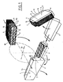
- the invention relates to a method and a machine specially intended for producing a package 1 which is not in itself the subject of the invention, in particular for eggs, of the type comprising two rigidly associated parts, namely a bottom 2 and a plate 3 in opposite directions.
- the packaging 1 is described in a possible embodiment only to better understand the process and the machine. It is understood that the packaging 1 can be the subject of other embodiments and that the method and the machine described later can therefore also have alternative embodiments adapted to the various embodiments of the packaging 1.
- the packaging 1 is described with respect to a normal position of use flat horizontally. However, it is understood that the packaging 1 can take any other position.
- the bottom 2 is lower and made in particular of cardboard so as to have a certain strength or rigidity. It has a lower horizontal main wall 4, generally of rectangular shape, and four respectively longitudinal 5 and lateral 6 flaps associated with the wall 4 by fold lines 7. The bottom 2 can then appear initially and before constitution of the packaging 1 in the form of a flat cut. Once incorporated into the packaging 1, the flaps 5, 6 - after their folding around the lines 7 - are arranged at least substantially vertically and directed upwards, that is to say at least substantially perpendicular to the wall 4 .If necessary, the flaps 5, 6 are slightly converging upwards, the main wall 4 forming a large base.
- the plate 3 is upper and produced in particular by means of a thermoformed plastic sheet. It comprises, firstly, hollow cells 8, normally open upwards, generally distributed in rows and columns, associated with each other, on the side of their openings by coplanar plates constituting a face upper 9 and, secondly, four respectively longitudinal 10 and lateral 11 edges adjacent to the upper face 9 on the same side as the cells 8.
- the plate 3 is preformed and the edges 10, 11 are arranged at least substantially vertically and directed downward, that is to say, at least substantially perpendicular to the face 9. Where appropriate, the edges 10, 11 are also slightly diverging downward, the face 9 constituting a small base.
- the bottom 2 and the plate 3 are rigidly associated with one another, in particular by the flaps 5, 6 and the edges 10, 11, these preferably being glued.
- the free edges 12, coplanar, of the edges 10, 11 rest on the wall 4 at the place or an immediate vicinity of the fold lines 7.
- the free edges 13 of the flaps 5, 6 are located between the wall 4 and the face 9, that is to say that the flaps 5, 6 do not project above the face 9.
- the flaps 5, 6 are outside and the edges 10, 11 inside and, on the other hand, the flaps and edges 5, 6, 10, 11 are slightly inclined vertically, by a few degrees, the packaging 1 thus having a general external shape slightly truncated-pyramid to large lower base (wall 4) and small upper base (face 9).
- the bottom 2 and the plate 3 are rigidly associated with one another by the bottom of the cells 8 in contact and glued to the main wall 4.
- the flaps 5, 6 and the edges 10, 11 can be snapped together (or glued).
- edges 10, 11 may be discontinuous and constituted by sections of walls of the cells 8. And, the edges may comprise, in the vicinity of the upper face 9, a peripheral groove in which the flaps are engaged and possibly maintained 5, 6.
- a bottom 2 and a preformed plate 3 are first grasped, the flaps being flat, not folded. Then place one on the other the bottom 2 and the tray 3 thus captured so that the edges 10, 11 of the tray 3 are directed towards and applied to the main wall 4 of the bottom 2, the main wall 4 and the upper face 9 being spaced from one another. They are then pressed against each other the bottom 2 and the plate 3 by acting on the side of the upper face 9 opposite the edges 10, 11. We rigidly associate the bottom 2 and the plate 3. And finally, we folds the flaps 5, 6 upwards towards the upper face 9 and they are rigidly associated with the edges 10, 11, outside of these.
- funds 2 and plates 3 are produced beforehand, the funds 2 being able to be stacked flat and the preformed plates 3 being able to be stacked, embedded or nested one inside the other.
- the folding of the flaps 5, 6 around the folding lines 7 aims to pass them from their original position where they are coplanar to the wall 4 and in which the plate 3 is placed on the bottom 2, to their final position where they are applied to the edges 10, 11, outside, at least substantially perpendicular to the wall 4.
- flaps 5, 6 are associated with the edges 10, 11, rigidly and permanently, in particular by gluing or by welding, by ultrasound, or any equivalent means or in a more or less removable manner, in particular by snapping in particular of the free edges. flaps 5, 6 in reserves made on the plate 3, in particular in the vicinity of the upper face 9.
- the flaps 5, 6 are folded when the bottom 2 and the plate 3 are pressed against each other, so as to stiffen the edges 10, 11 between the upper face 9 and the main wall 4.
- the flaps 5, 6 and / or the edges 10, 11 are glued and the flaps 5, 6 are folded against the edges 10, 11.
- the opposite sides are glued to the bottom of the cells 8 and / or of the main wall 4 and they are applied one against the other; and the flaps 5, 6 and the edges 10, 11 are combined, in particular by snap-fastening.
- the packaging 1 is maintained by its lateral faces 14.
- FIGS. 2A to 2D which make it possible to clearly understand the phase of association of the bottom 2 with the plate 3, in the case of the first variant envisaged.
- the invention also relates to a method for gripping a preformed tray 3 of the type described above from a stack of preformed trays 3 nested one inside the other.
- This input method is more specifically, but not limited to, applicable to the packaging production method described above.
- the first plate 3 is initially maintained by its upper face 9; then at least substantially simultaneously, we first grasp and then move the first plate 3 on the one hand, by the interior of its cells 8 and, on the other hand, by the free edges 12 of its edges 10, 11 .
- edges 10, 11 of the second plate 3 are deformed inwards so as to favor the extraction of the first plate 3 relative to the second plate 3 .
- the first plate 3 is initially maintained by the edges of its upper face 9 adjoining the edges 10, 11.
- the first plate 3 is grasped by the interior of its cells 8 by suction.
- FIGS. 3A and 3B make it possible to clearly understand the variant proposed as regards the gripping phase of the plate 3.
- the plates 3 are stacked and fitted together with a first front plate 3 (referenced 31) , a second plate 3 placed immediately after the first plate 31 (referenced 32) and so on an n th plate 3 (referenced 3n).
- the first plate 31 is maintained by its upper face 9, in particular by its edges adjoining the edges 10, 11. Then, simultaneously (FIG. 3B), the first plate 31 is grasped, towards the front by its alveoli 8, by suction and, towards the rear, by its free edges 12. For this step, the edges 10, 11 of the second plate 32 are previously deformed inwards and the stack of plates 3 is laterally tightened.
- the deformation edges 10, 11 of the second plate 32 promotes the extraction of the first plate 31 with respect to the second plate 32 by a double function: reduction of the friction of the edges in contact with the two plates 31 and 32; communication with the external ambient atmosphere of the cavity created between the two plates 31 and 31, which, failing this, would prevent the extraction of the first plate 31 held by suction, at the rear.
- the lateral clamping of the stack of trays 3 - with the exception of the first tray 31 aims to keep the stack stationary when the first tray 31 is extracted from it.
- the invention also relates to a machine specially adapted for producing packaging 1.
- This machine comprises: . separate means for gripping a bottom 2, the flaps 5, 6 of which are flat, not folded and of a preformed plate 3, respectively 15 and 16; . downstream of the gripping means 15, 16, means for placing the bottom 2 and the plate 3 on one another so that the edges 10, 11 of the plate 3 are directed towards and applied to the main wall 4 of the bottom 2, the main wall 4 and the upper face 9 being spaced from one another; . means for pressing 18 against each other the bottom 2 and the plate 3 acting on the side of the upper face 9 opposite the edges 10, 11, these means for pressing comprising two parts acting on the bottom 2 and the plate 3 separated transversely from each other; .
- means for associating the flaps 5, 6 on the edges 10, 11 outside of these. means, distinct or not, of rigid association, of the bottom 2 and of the plate 3.
- the machine also comprises means 19 for holding the packaging 1 by its lateral faces 14.
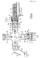
- the machine is of the carousel type and comprises an indexed wheel 20 of axis 21, preferably horizontal, having at least three but preferably four work stations 22, driven step by step. 'a quarter turn (in the case of four stations 22) by a motor not shown.
- the wheel 20 is associated with supply means 23 for the plates 3, supply means 24 for the bottoms 2 and discharge means 25 for the packages 1 produced located opposite three successive stations 22.
- This structure of the machine makes it possible to define respectively a set for gripping a plate 3 comprising the gripping means 16, a set for positioning and rigid association of a plate 3 with a bottom 2 comprising the gripping means 15, as well as the means 17, 18, 19 and, finally, a package evacuation assembly 1 made from the machine. Subsequently, and for reasons of simplicity, the positions 221 for gripping the plate 3, the positions 222 for positioning and association and the positions 223 for evacuation are designated respectively, the positions 22 being in the sets thus defined. . In the case of a wheel 20 with four stations 22, the fourth station 224 is said to be a rest station.
- each station 22 becomes successively a station 221 then a station 222 then a station 223 and finally a station 22 poste.
- the entry station 221 and the evacuation station 223 are such that the corresponding branches 29 are horizontal.
- the positioning and association station 222 is such that the corresponding branch 29 is vertical and directed downwards.
- Each station 22 comprises on the one hand, a gripping member 26 of a plate 3 from the inside of its cells 8, comprising in particular suction means, radially movable and, on the other hand, the holding means 19 of the packaging 1 by its lateral faces 14, fixed.
- Drive means 27 make it possible to move the gripping member 26 between two extreme inner and outer radial positions, respectively.
- the movable characters of the gripping member 26 and the fixed of the holding member 19 refer to the wheel 20
- the gripping member 26 is in the form of a complementary imprint of the cells 8, with which are associated suction means by air - not shown - intended to keep a plate 3 firmly applied to the imprint 26.
- These means air suction comprise a vacuum source or air suction means as well as sectioning means, well known per se to the skilled person.
- the gripping member 26 is carried perpendicularly to the outer end of a radial and mobile rod 28 guided so as to be able to slide radially in a branch 29 of the wheel 20 corresponding to the station 22.
- the rod 28 cooperates, on the side of axis 21 with a cam not shown. This cam and the rod 28 are part of the drive means 27.
- the gripping member 26 is also part of the gripping means 16 described later.
- the holding means 19 consist of a frame extending in a plane orthogonal to the rod 28, fixedly carried by crutches 30 at least substantially radial, fixed on either side of the branch 29 so as not to not interfere with the gripping member 26 during its movement.
- the internal dimensions of the frame 19 and its thickness correspond to the internal dimensions and the thickness of the packaging 1 so that the packaging 1 can be held by force, with gentle friction and by its lateral faces 14 in the frame 19.
- the outer opening of the frame 19 is flared outward to facilitate the cooperation of the frame 19 and the packaging 1.
- the gripping member 26 In its extreme internal position, the gripping member 26 is closest to the axis 21 and is placed inside the frame 19, substantially coplanar with it. This position occurs at the beginning and at the end of operation at the 221 input station of the trays 3, the 222 placement and association station, and the 223 evacuation station. This position is also that of the rest station 22 poste.
- the gripping member 26 In its extreme external position, the gripping member 26 is furthest from the axis 21 and is placed just outside the frame 19, spaced from it along the sliding axis of the member 26. This position is presented in an intermediate manner at the 221 entry station in order to carry out the entry of a plate 3, the establishment and association station 222 in order to carry out the pressing, and the discharge station 223 in order to carry out evacuation.
- the supply means 23 of the plates 3 can be the subject of several alternative embodiments. A particular variant embodiment, described later, is specially adapted to the case where the plates 3 are stacked and nested. In all cases, the supply means 23 are arranged so that the gripping member 26 can be lined with a plate 3.
- the means 24 for supplying funds 2 can also be the subject of several alternative embodiments.
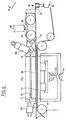
- a particular variant embodiment includes (FIG. 5) a magazine 31 in which the bottoms 2 are stacked flat; a movable extractor 32 associated with the magazine 31 intended to extract a bottom 2 of the magazine 31, this extractor 32 possibly being of the suction cup type, known per se to those skilled in the art; one or more belts or endless drive belt 33 extending parallel to the axis 21 in particular horizontally and below the positioning and association station 222; drive means, not shown, of the belt 33 step by step; possibly one or more motorized pressure rollers 34 arranged transversely above the belt 33.
- the belt 33 extends over a length making it possible to define three successive zones: .
- the drive means are arranged to pass a bottom 2 flat from one to the other of the zones 35, 37, 36 respectively.
- the discharge means 25 can also be the subject of several alternative embodiments.
- a particular variant comprises (FIG. 4) a deflecting plate 39, a receiving plate 40 both intended to guide a package 1 in line with the gripping member 26 of the evacuation station 223 towards an evacuation mat 41 or the like.
- the means 15 for gripping the bottom 2 comprise on the one hand, the belt 33 and on the other hand, a plate 42, horizontal, placed in the downstream area 36 vertically and below the frame 19 and the member gripping 26 of the station 222, movable vertically sliding between two extreme positions respectively lower retracted and upper discharge with an intermediate pressing position.
- the plate 42 is located to the right of the belt 33.
- the belt 33 can be of small transverse width and the plate 42, have two parts on either side of the belt 33.
- the belt 33 is single and axial and the plate 42 in two symmetrical parts.
- the external space requirement of the plate 42 is at most and preferably close to that of the wall 4, that is to say, up to the fold lines 7.
- the plate 42 is for example carried by the rod 43 of a jack 44 disposed orthogonally to the axis 20 and below the plate 42 and the belt 33.
- the plate 42 In its intermediate position, the plate 42 is at least substantially coplanar with the belt 33. This intermediate position occurs in the middle of the operation of the positioning and association station 222 (FIGS. 2B and 2C). In its lower retracted position, the plate 42 is inactive and housed under the belt 33. This lower retracted and inactive position occurs at the start of the operation of the positioning and association station 222 (FIG. 2A). In its upper evacuation position, the plate 42 is spaced vertically and upwards above the belt 33 and therefore is closest to the axis 21. In this upper evacuation position, the plate 42 supports the bottom 2 spaced from the belt 33. This upper position occurs at the end of the operation of the positioning and association station 222.
- the means 16 for gripping the plate 3 comprise the suction gripping member 26 and the supply means 23 of associated plates described later.
- the means 17 for placing the bottom 2 and the plate 3 on one another comprise, on the one hand, the gripping member 26 in the station 222 as well as the drive means 27 and in that they drive the gripping member 26 towards its extreme external position, that is to say towards the belt 33 and, on the other hand, the belt 33 in its downstream zone 36.
- the means 18 for pressing the bottom 2 and the plate 3 against each other comprise on the one hand, the gripping member 26 in the station 222 as well as the drive means 27 in that they are suitable maintaining the gripping member 26 in the extreme external position, and on the other hand, the plate 42 and its associated drive means 43, 44; the drive means 27, 43, 44, urging the gripping member 26 and the plate 42 one towards the other.
- the machine also comprises means for longitudinal gluing in two parts 38a and 38b, and means for lateral gluing in two parts respectively upstream and downstream 45a, 45b.
- These sizing means are constituted by nozzles projecting glue, such as hot melt glue, a relative movement existing between the nozzle and the bottom 2 to form a line of glue.
- the gluing means 38a, 38b, 45a, 45b have the function of depositing lines of glue on the longitudinal and side flaps 5 6.
- the two parts of the longitudinal gluing means 38a, 38b are placed opposite one another, on either side of the means 24 for supplying the bottoms 2, in particular in the intermediate zone.
- the longitudinal gluing means 38a, 38b operate "in the parade” during the longitudinal movement of the bottoms 2 on the belt 33.
- the two parts of the upstream lateral gluing means 45a and downstream 45b are placed respectively at the start and at the end of the downstream zone 36, in particular on either side of the frame 19, of the gripping member 26 and of the plate. 42 in the longitudinal direction of movement of the belt 33 and the bottom 2.
- the two parts of the lateral gluing means 45a, 45b are mounted with transverse horizontal sliding and driven on either side of the feeding means 24 thanks to drive means not shown such as a jack.
- a jack drives a carriage carrying the two parts 45a, 45b.
- the gluing means 38a, 38b, 45a, 45b are placed vertically above but close to the plane of the belt 33 or the plate 42 in the intermediate position.
- the machine also includes folding means 46 for the flaps 5, 6 around the fold lines 7, vertically and upwards to bring them against the edges 10, 11.
- These folding means 46 are constituted, for example, by a frame placed horizontally around the plate 42.
- the frame 46 is movable with vertical sliding between two extreme positions, respectively retracted lower and upper folding.
- the frame 46 is, for example, carried by the body of the jack 44, this jack body being movably mounted to slide along a vertical axis. This arrangement facilitates the realization of the drive means of the plate 42 and the frame 46 so that they can be moved independently of one another, but in combination. the body of the jack 44 can then be driven by one or more jacks or even by a cam.
- the frames 19 and 46 have at least substantially the same opening.
- the frame 46 In the extreme lower position retracted, the frame 46 is located under the belt 33. This position occurs at the start of operation of the second station 222 ( Figures 2A and 2B).
- the frame 46 In the extreme upper position, the frame 46 is located immediately above the belt 33. This position occurs at the end of the operation of the second station ( Figures 2C and 2D).
- the plate 42 In this upper position of the frame 46, the plate 42 can also be in the upper extreme position above the frame 46 and this in the last step of the operation of the second station 222.
- a tray 3 is gripped by the gripping member 26 at station 221.
- a bottom 2 flat is delivered by the supply means 24 to the downstream area 36 of the station 222.
- the rotation of a step of the wheel 20 makes it possible to bring the plate 3 to the station 222.
- the application of the gluing means 38a, 38B, 45a, 45b has made it possible to glue the internal faces of the flaps 5, 6.
- the bottom 2 and the plate 3 at station 222 are opposite and vertically vertically from one another but initially spaced from one another, the gripping member 26 being in its extreme interior position, the plate 42 and the frame 46 in their lower retracted extreme position (FIG. 2A). Then, the gripping member 26 is brought into the extreme external position, until the free edges 12 are in abutment on the bottom 2. Simultaneously, the plate 42 is brought to the intermediate position so as to firmly hold the bottom 2 in the plane of the belt 33 ( Figure 2B). Then, the gripping member 26 and the plate 42 remain in this same position and the frame 46 is moved to its extreme upper folding position (FIG. 2C).
- the bottom 2 and the plate 3 are pressed simultaneously, one against the other, to ensure the rigidity of the edges 10, 11 by tensioning as indicated above and the folding of the flaps 5, 6 against the edges 10, 11.
- the contact of the flaps 5, 6 glued and the flaps 10, 11 causes them to join.
- the frame 46 remaining in its same position, the gripping member 26 and the plate 42 are moved in synchronism vertically and upwards until they reach the inner extreme position and the upper extreme position respectively. It follows the transfer of the bottom 2-plate 3 assembly from the frame 46 to the frame 19, the two frames being placed facing each other and in close proximity to each other.
- Another aspect of the invention relates to the supply means 23 and the gripping means 16. These means are applicable in particular but not exclusively to the machine which has just been described.
- the supply means 23 comprise a conveyor belt 47 having a step-by-step advancement by means of appropriate drive means 48.
- the conveyor belt 47 is extended forward by a coplanar fixed plate 49 and in particular horizontal.
- the conveyor belt 47 and the plate 49 make it possible to support a stack of nested trays 3 resting on their edges, in particular the longitudinal edges 10 below.
- the supply means 23 also include a lateral clamping plate 50, in particular at least substantially horizontal, placed above the plate 49, movable for example, pivoting about a transverse axis 51, moved by a jack 52 or similar, between two extreme positions: a clamping position and a retracted position.
- a clamping position the clamping plate 50 is applied to the edges, in particular the upper longitudinal edges 10 of the plates 3. This position occurs at the end of the operation of the station 221 ( Figure 3B).
- the clamping plate 50 In the retracted position, the clamping plate 50 is separated from the edges of the plates 3. This position occurs at the start of operation of the station 221 ( Figure 3A).
- the function of the clamping plate 50 is to hold the stack of trays 3 when this stack is no longer held by the other members of the supply means 23.
- the feeding means 23 also include claws or the like 53a, 53b, at least substantially vertical and transverse, mobile, in particular pivoting about transverse axes 54a, 54b, displaced by a linkage 55, itself, controlled by a cam or cylinder.
- claws 53a, 53b are intended to engage on the upper face 9 of the first plate 31 of the stack of trays 3. the claws, 53a, 53b therefore constitute a retractable front stop, ensuring a positive hold of the stack.
- the claws 53a, 53b can be in two extreme positions, respectively active and inactive retracted. In the active position, the claws 53a, 53b actually come to form a front stop for the first 31 tray. This active position occurs in particular in the retracted position of the plate 50. In the inactive retracted position, the claws 53a, 53b do not hold the first plate 31 and do not prevent its pressing. This retracted inactive position occurs in particular in the plate 50 clamping position.
- the supply means 23 finally comprise a pusher frame 56 placed vertically and transversely, movable with horizontal and longitudinal sliding (that is to say, parallel to the direction of the conveyor belt 47 and the plate 49, c ' that is to say also the direction of advancement of the plates 3), by means of a linkage 57 controlled by a cam or a jack.
- the pusher frame 56 can occupy two extreme positions: a rear retracted position and a position before extended.
- the pusher frame 56 has an opening 58 corresponding to the outer contour of the plates 3 - that is to say the edges 10, 11- so as to be adjusted to the plates 3, as mentioned below.
- the opening 58 is preferably pyramidal or beveled so as to be slightly larger at the rear 58a than at the front 58b.
- the rear opening 58a is slightly larger than the largest size of the plates 3 - in particular at the location of the free edges 12 and the front opening 58b is slightly smaller than the largest space of the plates 3 or even slightly smaller than the smallest footprint of the plates 3, in particular at the location of the upper face 9.
- the sliding movement of the pusher frame 56 rearward does not create any annoying interference with the stack of trays 3.
- the front opening 58b forms a stop or pawl and fulfills two functions: on the one hand, slightly deforming the edges inwards 10, 11 of the second plate 32 and, on the other hand, come to lock on the free edges 12 of the first plate 31.
- the deformation of the edges 10, 11 of the second plate 32 has itself two functions: the first to reduce the friction on each other of the edges 10, 11 of the plates 31 and 32.
- the second allows air to enter between the two plates 31 and 32 to prevent them from sticking to each other due to the vacuum prevailing between them.
- the pusher frame 56 In the retracted rear position, the pusher frame 56 is located at the rear and away from the claws 53a, 53b, in line with the plates 49 and 50. In the position before output, the pusher frame 56 is located immediately behind the claws 53a, 53b.
- the supply means 23 are arranged generally horizontally opposite the first station 221, the claws 53a, 53b being near the station 221. More precisely, the supply means 23 are arranged, relative to the first station 221 so that in the position before exit, the pusher frame 56 is located in the immediate vicinity - in particular is tangent - to the gripping member 26 in position extreme exterior.
- the pusher frame 56 essentially constitutes a unit for extracting a unit from a tray 3 from the stack of the tray 3.
- the means 16 for gripping the trays 3 thus essentially consist of the gripping member 26 and the pusher frame 56.
- the device that has just been described operates as follows: Initially, the clamping plate 50 is in the retracted position, the claws 53a, 53b in the active position, the pusher frame 56 in the retracted rear position, the gripping member 26 in the extreme interior position (FIG. 3A). In this situation, the stack of trays 3 is at rest, the member 26 being devoid of trays. In this situation, the belt 47 can advance one step to properly lock the first plate 31 against the claws 53a, 53b. Then, the clamping plate 50 passes into the clamping position, the claws 53a, 53b pass into the retracted position, the pusher frame 56 is slid forward (relative to the direction of advance of the belt 47) and the member seizure 26 is advanced outward.
- the stack of trays 3 is held between the plates 49 and 50, while the pusher frame 56 extracts the first tray 31 from the stack.
- the pusher frame 56 and the gripping member 26 move towards each other, until the first plate 31 is gripped by the member 26 by means of the suction means.
Landscapes
- Making Paper Articles (AREA)
Applications Claiming Priority (2)
| Application Number | Priority Date | Filing Date | Title |
|---|---|---|---|
| FR8615615A FR2606327A1 (fr) | 1986-11-07 | 1986-11-07 | Procede et machine pour la realisation d'un emballage en deux parties |
| FR8615615 | 1986-11-07 |
Publications (1)
| Publication Number | Publication Date |
|---|---|
| EP0270420A1 true EP0270420A1 (de) | 1988-06-08 |
Family
ID=9340669
Family Applications (1)
| Application Number | Title | Priority Date | Filing Date |
|---|---|---|---|
| EP87402521A Withdrawn EP0270420A1 (de) | 1986-11-07 | 1987-11-06 | Verfahren und Vorrichtung zum Verfertigen einer Verpackung aus zwei mit einander verbundenen Teilen, insbesondere für Eier |
Country Status (2)
| Country | Link |
|---|---|
| EP (1) | EP0270420A1 (de) |
| FR (1) | FR2606327A1 (de) |
Citations (7)
| Publication number | Priority date | Publication date | Assignee | Title |
|---|---|---|---|---|
| GB952930A (de) * | 1900-01-01 | |||
| US2002213A (en) * | 1933-12-26 | 1935-05-21 | Charles F Adams | Cup dropping machine |
| US2081910A (en) * | 1932-12-03 | 1937-06-01 | Burt Co Ltd F N | Forming machine |
| US3661282A (en) * | 1970-03-04 | 1972-05-09 | Scott Paper Co | Method of continously moving containers through a treatment process |
| US4109803A (en) * | 1977-02-14 | 1978-08-29 | Quelch Alan Ralph | Method and apparatus for de-stacking trays |
| GB2059868A (en) * | 1979-10-09 | 1981-04-29 | Haendle & Soehne Maschf Karl | Machine for covering boxes with a cardboard or foil blank |
| AT380854B (de) * | 1984-01-19 | 1986-07-25 | Kreuziger Wolf Dieter Mag Ing | Vorrichtung zur handhabung von in einem stapel vorliegenden offenen gefaessen |
Family Cites Families (3)
| Publication number | Priority date | Publication date | Assignee | Title |
|---|---|---|---|---|
| US1343748A (en) * | 1917-06-08 | 1920-06-15 | Stokes & Smith Co | Box-covering machine |
| US2937786A (en) * | 1957-05-16 | 1960-05-24 | Muller Paper Goods Company Inc | Paper crinkle cup separating device |
| JPS60202019A (ja) * | 1984-03-26 | 1985-10-12 | Katsumi Yoshida | 合成樹脂薄板製包装用容器の分離装置 |
-
1986
- 1986-11-07 FR FR8615615A patent/FR2606327A1/fr active Pending
-
1987
- 1987-11-06 EP EP87402521A patent/EP0270420A1/de not_active Withdrawn
Patent Citations (7)
| Publication number | Priority date | Publication date | Assignee | Title |
|---|---|---|---|---|
| GB952930A (de) * | 1900-01-01 | |||
| US2081910A (en) * | 1932-12-03 | 1937-06-01 | Burt Co Ltd F N | Forming machine |
| US2002213A (en) * | 1933-12-26 | 1935-05-21 | Charles F Adams | Cup dropping machine |
| US3661282A (en) * | 1970-03-04 | 1972-05-09 | Scott Paper Co | Method of continously moving containers through a treatment process |
| US4109803A (en) * | 1977-02-14 | 1978-08-29 | Quelch Alan Ralph | Method and apparatus for de-stacking trays |
| GB2059868A (en) * | 1979-10-09 | 1981-04-29 | Haendle & Soehne Maschf Karl | Machine for covering boxes with a cardboard or foil blank |
| AT380854B (de) * | 1984-01-19 | 1986-07-25 | Kreuziger Wolf Dieter Mag Ing | Vorrichtung zur handhabung von in einem stapel vorliegenden offenen gefaessen |
Also Published As
| Publication number | Publication date |
|---|---|
| FR2606327A1 (fr) | 1988-05-13 |
Similar Documents
| Publication | Publication Date | Title |
|---|---|---|
| EP0334707B1 (de) | Verfahren und Maschine für die Herstellung von polygonalen Schachteln aus Bogenmaterial und daraus hergestellte Schachtel | |
| EP0605268B1 (de) | Verpackung mit vieleckigem Querschnitt aus Blattmaterial, insbesondere für Flaschen, Zuschnitt und Maschine für eine solche Verpackung | |
| EP2619118B1 (de) | Vorrichtung für den transport von bündeln für eine umreifungsmaschine | |
| FR2532619A1 (fr) | Procede de preparation de paquets d'articles imprimes arrivant dans une disposition de chevauchements et prets a l'expedition | |
| EP1188676A1 (de) | Satz von Zuschnitten, Verfahren und Vorrichtung zum Verpacken eines Produktes oder einer Menge Artikeln nichtspezifischer Form | |
| EP0281484A1 (de) | Verfahren zur Regelung des Ausmasses eines Matrizensets für Zuschnitte; Matrizenset | |
| CH373688A (fr) | Procédé pour insérer une ébauche de séparation pliable entre des rangées de récipients à emballer et machine pour la mise en oeuvre de ce procédé | |
| EP1171355A1 (de) | Faltschachtel, zuschnitte, verfahren zur öffnung einer faltschachtel sowie verfahren und maschine zum herstellen von einer solchen faltschachtel | |
| EP0202998A1 (de) | Verfahren und Vorrichtung zum Aufrichten und teilweise Verschliessen von Kisten oder Faltschachteln aus Karton | |
| EP3526025B1 (de) | Vorrichtung und verfahren zur entfernung einer schachtel von einem dorn | |
| EP3526024B1 (de) | Verfahren und vorrichtung zum formen eines rohlings um eine spindel | |
| EP4711293A2 (de) | Verfahren und verpackungsmaschine zum verschliessen eines oben offenen quaderförmigen kastens durch eine kappe | |
| FR3089860A1 (fr) | Procédé et machine de formation de sacs flexibles à fond spécial | |
| FR2606327A1 (fr) | Procede et machine pour la realisation d'un emballage en deux parties | |
| EP1725393B1 (de) | Maschine und verfahren zur herstellung einer platte durch verwendung eines dorns | |
| EP0151364A2 (de) | Verpackungsstrasse für Produkte mit einem Film in einem aus einem flachen vorgeschnittenen Zuschnitt hergestellten Behälter | |
| EP2878540B1 (de) | Verschlussstation einer Lasche für eine Kartoniermaschine | |
| FR3161904A1 (fr) | Procédé et machine d’emballage pour la fermeture par une coiffe d'une caisse de forme parallélépipédique rectangle ouverte sur le dessus | |
| EP0697338A1 (de) | Verpackung für ein Produkt nichtspezifischer Form, Satz von Zuschnitten, Verfahren und Vorrichtung zur Herstellung einer solchen Verpackung | |
| FR3151576A1 (fr) | Machine d’ensachage de produits et procédé d’ensachage de produits à ensacher avec une telle machine | |
| JPH06171606A (ja) | フィルム包装方法及びその装置 | |
| FR2774941A1 (fr) | Procede et machine simplifiee pour la mise en volume de caisse tambour a partir de decoupes carton | |
| FR2518054A1 (fr) | Installation pour la pose d'un groupe d'objets, tels que des boites de conserve sur un support en vue de leur emballage | |
| FR2471851A1 (fr) | Procede et appareillage pour l'ouverture et la pose de troncons de gaine thermoplastique autour de recipients ou autres objets divers | |
| BE461794A (de) |
Legal Events
| Date | Code | Title | Description |
|---|---|---|---|
| PUAI | Public reference made under article 153(3) epc to a published international application that has entered the european phase |
Free format text: ORIGINAL CODE: 0009012 |
|
| AK | Designated contracting states |
Kind code of ref document: A1 Designated state(s): AT BE CH DE ES FR GB GR IT LI LU NL SE |
|
| 17P | Request for examination filed |
Effective date: 19881205 |
|
| STAA | Information on the status of an ep patent application or granted ep patent |
Free format text: STATUS: THE APPLICATION IS DEEMED TO BE WITHDRAWN |
|
| 18D | Application deemed to be withdrawn |
Effective date: 19900531 |
|
| RIN1 | Information on inventor provided before grant (corrected) |
Inventor name: VALLETEAU DE MOULLIAC, CHRISTIAN Inventor name: DELAUNAY,JEAN-PIERRE |