EP0270730A2 - Farbwechselvorrichtung - Google Patents
Farbwechselvorrichtung Download PDFInfo
- Publication number
- EP0270730A2 EP0270730A2 EP87107283A EP87107283A EP0270730A2 EP 0270730 A2 EP0270730 A2 EP 0270730A2 EP 87107283 A EP87107283 A EP 87107283A EP 87107283 A EP87107283 A EP 87107283A EP 0270730 A2 EP0270730 A2 EP 0270730A2
- Authority
- EP
- European Patent Office
- Prior art keywords
- iris
- leaves
- control plate
- color
- control
- Prior art date
- Legal status (The legal status is an assumption and is not a legal conclusion. Google has not performed a legal analysis and makes no representation as to the accuracy of the status listed.)
- Withdrawn
Links
- 239000003086 colorant Substances 0.000 claims abstract description 11
- 238000001228 spectrum Methods 0.000 claims abstract description 6
- 238000004040 coloring Methods 0.000 claims abstract description 3
- 230000007246 mechanism Effects 0.000 description 5
- 239000000463 material Substances 0.000 description 3
- 238000002955 isolation Methods 0.000 description 2
- 230000004048 modification Effects 0.000 description 2
- 238000012986 modification Methods 0.000 description 2
- 235000014036 Castanea Nutrition 0.000 description 1
- 241001070941 Castanea Species 0.000 description 1
- 239000011521 glass Substances 0.000 description 1
- 238000005286 illumination Methods 0.000 description 1
- 230000013011 mating Effects 0.000 description 1
- 239000002184 metal Substances 0.000 description 1
- 230000007935 neutral effect Effects 0.000 description 1
Images


Classifications
-
- F—MECHANICAL ENGINEERING; LIGHTING; HEATING; WEAPONS; BLASTING
- F21—LIGHTING
- F21V—FUNCTIONAL FEATURES OR DETAILS OF LIGHTING DEVICES OR SYSTEMS THEREOF; STRUCTURAL COMBINATIONS OF LIGHTING DEVICES WITH OTHER ARTICLES, NOT OTHERWISE PROVIDED FOR
- F21V11/00—Screens not covered by groups F21V1/00, F21V3/00, F21V7/00 or F21V9/00
- F21V11/08—Screens not covered by groups F21V1/00, F21V3/00, F21V7/00 or F21V9/00 using diaphragms containing one or more apertures
- F21V11/10—Screens not covered by groups F21V1/00, F21V3/00, F21V7/00 or F21V9/00 using diaphragms containing one or more apertures of iris type
-
- F—MECHANICAL ENGINEERING; LIGHTING; HEATING; WEAPONS; BLASTING
- F21—LIGHTING
- F21V—FUNCTIONAL FEATURES OR DETAILS OF LIGHTING DEVICES OR SYSTEMS THEREOF; STRUCTURAL COMBINATIONS OF LIGHTING DEVICES WITH OTHER ARTICLES, NOT OTHERWISE PROVIDED FOR
- F21V9/00—Elements for modifying spectral properties, polarisation or intensity of the light emitted, e.g. filters
- F21V9/40—Elements for modifying spectral properties, polarisation or intensity of the light emitted, e.g. filters with provision for controlling spectral properties, e.g. colour, or intensity
Definitions
- This invention relates generally to spotlight systems and more particularly to a spotlight apparatus mounted with a spotlight for changing the colors of the spotlight beam.
- Spotlights are generally called upon to throw not only white, or colorless, beams but also color beams of varying colors, hues, and intensities that can be selected by an operator from a range of colors and color combinations across the complete range of the color spectrum.
- One color changer mechanism known in the art uses a series of individually hinged color lenses, or boomerangs, each of a basic color of the light spectrum and hinged at the end of the spotlight housing so that any or any combination of the colored lenses can be rotated by an operator to a position at the emission end of the beam.
- the colors of the color lenses are such that the range of the spectrum is available.
- the operator selects one color lens then rotates the selected lens across the light beam.
- two or more selected color lenses which when mated with one another will produce a desired color, can be rotated across the light beam.
- an object of the present invention to provide a color changer system for a spotlight that can be easily operated to change the color of the light beam being projected in a subtle manner.
- the present invention achieves the above objects by converting a shutter-type dimmer mechanism known in the art to a color changer system for a spotlight.
- the present invention includes a color changer system mounted at the light beam emission end of a luminaire housing.
- the system includes a support frame secured to the housing disposed transverse to the beam, a plurality of iris units each having a plurality of colored, translucent leaves rotatably attached to the support frame, and a circular control plate rotatably mounted to the support frame and having a control slot in which a thrust pin of each leaf is slidably movable and a control handle.
- the support frame and the control plate each have circular apertures with centers that are aligned with the beam axis. When the control plate is rotated, the leaves of each iris unit open or close in response to pressure by the control plate against a thrust pin so as to control the coloring of the light beam.
- the leaves move inwardly from the periphery of the light beam towards the beam axis towards a closed position or move away from the beam axis so as to intercept all or a portion of the light beam so as to filter the light beam through the intercepting leaves so as to color that portion of the intercepted beam.
- the leaves of each iris unit each have a different color from the leaves of the other iris units, with the colors preferably including the primary colors of the spectrum.
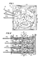
- a color changer system 10 is illustrated in isolation in Figures 1-3 and schematically mounted in a luminaire, or housing, 12 in Figure 4.
- Housing 12 contains a light source 14 and a lens 16, but may include a number of other devices known in the art of stage illumination including an iris, a shutter, a mechanical dimmer, and an extended lens system.
- Light source 14 emits a light beam 18 centered about an axis 20. Beam 18 is emitted generally as a colorless, or white, beam and is directed to the beam emission end 22 of housing 12.
- a series of iris units 28A, 28B, 28C, and 28D each rotatably connected to its own generally flat support frame 30 are positioned perpendicular to beam 18 and secured to housing 12 at beam emission end 22 by a number of bolts 26 in a manner known in the art.
- Iris units 28A-28D are slightly spaced apart and parallel with one another with iris unit 28A nearest to entering beam 18 from light source 14 and iris unit 28D farthest.
- Each of the four support frames 30 has a circular aperture 32 having a center that is aligned with axis 20.
- Each control plate 34A-34D is rotatably positioned in the arcs of stepped supports 38 at circumferential edges 36A-36D so as to be freely rotatable laterally relative to each support frame 30 and iris units 28A-28D.
- Four hold-down members 40 have their one end screwed into each support frame 30 at stepped supports 38 and their opposite ends pressed against the beam-facing flat surface of each of control plates 34A-34D so as to keep each control plate rotatably mounted to each support frame 30.
- Each control plate 34A-34D has a respective central aperture 42A-42D of the same radius as aperture 32 of support frame 24 and having a center aligned with beam axis 20.
- control handles 44A-44D include hand gripping portions that extend outwardly from circumferential edges 36A-36D to connecting portions that are secured to control plates 34A-34D, respectively, by a pair of screws.
- the connecting portions of handles 44A-44D are disposed in the space between each iris unit 28A-28D and each support frame 30.
- Each of the iris units 28A-28D includes three similarly shaped, colored or filtered, translucent iris leaves 46, which are centered about and disposed perpendicular to beam axis 20.
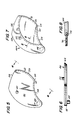
- a single iris leaf 46 is shown in isolation in Figures 5 and 6.
- Each leaf 46 is rotatably mounted to the beam-facing surface of support frame 24 by a pivot member 48, which is rotatably positioned in pivot holes in the beam-facing surface of support frame 24.
- a thrust pin 50 extends perpendicularly from the reverse surface from pivot member 48 of each leaf 46.
- Each control plate 34A-34D has an elongated control slot 52 in which a thrust pin 50 is engaged and slidingly movable along the slot as will be explained in detail below.
- Leaves 46 of each set of iris units 28A-28D is colored differently from the other. As shown in Figures 1-3, the iris leaves 46 of iris unit 28A is of one primary color, he iris leaves 46 of iris unit 28B is of a second primary color, and the iris leaves 46 of iris unit 28C is of a third primary color. Leaves 46 of iris unit 28D are of a neutral, tinted shade that function to subdue the intensity of the colors of iris units 28A-28C.
- Each of the iris units 28A-28D is movable between an open position and a closed position including a plurality of intermediate positions between the open and closed positions.
- beam 18 passes iris leaves 46, which are rotatably completely withdrawn from aperture 42 of support frame 30.
- beam 18 passes through the three translucent leaves 46, which completely cover aperture 42 so that beam 18 is fully colored in accordance with the particular color of the leaves of the particular iris unit that is closed.
- leaves 46 of each iris unit are successively positioned across a portion of beam 18 and extend from from the periphery of beam 18 to positions spaced from beam axis 20. As leaves 46 are simultaneously moved inwardly or outwardly, they close toward or from beam axis 20, respectively, so that an increasingly less or greater amount of light passes through the apertures centered around beam axis 20.
- control handle 44A In operation an operator moves one of the control handles 44A-44D for its respective control plate 34A-34D and rotates the control plate by upward or downward movement of the control handle.
- control handle 44A In Figures 1 and 2 control handle 44A is in a raised position and leaves 46 of iris unit 28A completely cover aperture 32 so that beam 18 is completely colored by the first primary color upon passing through translucent leaves 46.
- control handle 44A In Figure 3 control handle 44A has been moved to a down position so that leaves 46 of iris unit 28A have been completely withdrawn from aperture 32 of its support frame 30 so that beam 30 is not colored as it passes iris unit 28A.
- iris unit 28B is shown with its leaves 46 in a half-closed position so that beam 18 is colored by the second primary color around the outer portion of the beam from the periphery of the beam to about half the radius of the beam while the remaining center portion centered about beam axis 20 is uncolored.
- Iris unit 28C is shown in about a three-quarters closed position with beam 20 colored with the second primary color about three-fourths of the radial distance from its periphery with about one-fourth of the radial distance from beam axis 20 uncolored.
- leaves 46 of each control unit 28B and 28B are indicated as the control units themselves for purposes of illustration so that the positions of the leaves in each position can be seen.
- Iris unit 28D is shown in a completely closed position.
- thrust pin 50 When the selected control plate 34A-34D is rotated, thrust pin 50 is pressured by the side walls of elongated control slot 52 from its former position relative to its support plate 30A-30D to a new position.
- thrust pins 50 are positioned proximate apertures 42A-42D when leaves 46 are in their closed mode as shown for control plate 34A in Figures 1 and 2 and are positioned distant from apertures 42-42A when leaves 46 are in their closed mode as shown for control plate 34A in Figure 3.
- thrust pin 50 In the intermediate positions, thrust pin 50 is forced to intermediate positions between the proximate and distant positions just discussed from the control plate aperture so that leaves 46 are positioned partly across beam 20.
- leaves 46 The exact configuration of leaves 46 is illustrated in Figure 5.
- An inwardly curved wall 54 of each leaf 46 aligns with apertures 42A-42D when in the completely open mode, and in the closed mode inwardly curved wall 54 fits against an outwardly curved wall 56 of the adjoining leaf.
- Another outwardly slightly curved wall 58 is pressed against a portion of a support boss 38 when leaf 46 is in its open mode.
- Two of leaves 46 have projecting edges, or lips, 60 and 62 along walls 54 and 56, respectively. In the leaf shown in Figure 5, lips 60 and 62 project from the beam-facing surface of leaf 46, but its mating leaf in the closed mode has its lips projecting from the reverse surface so that the lips lock.
- the third leaf 46 has a middle lip 64, seen best in Figure 2, projecting from walls 54 and 56 so that the lips from the other two leaves fit above and below lip 64.
- the three leaves 46 converge at a central point 66 aligned with beam axis 20 at the juncture of walls 54 and 56 when the three leaves 46 are in their fully closed mode.
- the number of leaves for each iris unit may vary from the three leaves shown herein.
- the leaves may be made any of a variety of materials including colored plastic material or colored glass with a metal support trim.
- FIGs 7 and 8 illustrate an alternate embodiment of a leaf indicated as leaf 46A, which includes a mounting portion 68 and a translucent portion 70.
- Mounting portion 68 is made of a stronger material than translucent portion 70.
- Mounting portion 68 is never positioned so as intercept light rays 20.
- Mounting portion 68 and translucent portion 70 are joined along an annular juncture 72, which is aligned with the circular edge of circular apertures 42A-42D of control plates 34A-34D when the leaves are in their closed mode.
- Mounting portion 68 has an annular slot 73 along the concave side of juncture 72 that is adapted to slidably position the convex side of translucent portion 70.
- Mounting portion 68 and translucent portion 70 are cemented together.
- Figures 9 and 10 illustrate an alternative embodiment of the controls for control plates 34A-34D to control handles 44A-44D discussed earlier.
- Figure 9 which is a slightly simplified version of the view shown in Figure 2, shows four motors 74A-74D with their drive shafts 76A-76D, respectively, connected to drive gears 78A-78D, respectively, which are geared to gear teeth 80A-80D of control plates 34A-34D, respectively.
- Figure 10 illustrates a typical control system for a typical control plate 34 having gear teeth 80 over a portion the circumference of the control plate.
- a motor 74 shown in phantom line, rotates drive shaft 76 and drive gear 78 at the end of the drive shaft.
- Drive gear 78 is geared to gear teeth 80. Controls for each motor lead to a control panel (not shown) so as to give the operator the ability to control all the iris leaves 46 operated by control plates 34A-34D.
Landscapes
- Engineering & Computer Science (AREA)
- General Engineering & Computer Science (AREA)
- Physics & Mathematics (AREA)
- Spectroscopy & Molecular Physics (AREA)
- Non-Portable Lighting Devices Or Systems Thereof (AREA)
- Optical Filters (AREA)
- Securing Globes, Refractors, Reflectors Or The Like (AREA)
Applications Claiming Priority (2)
| Application Number | Priority Date | Filing Date | Title |
|---|---|---|---|
| US06/939,348 US4811182A (en) | 1986-12-08 | 1986-12-08 | Color changer |
| US939348 | 1986-12-08 |
Publications (2)
| Publication Number | Publication Date |
|---|---|
| EP0270730A2 true EP0270730A2 (de) | 1988-06-15 |
| EP0270730A3 EP0270730A3 (de) | 1989-08-30 |
Family
ID=25473025
Family Applications (1)
| Application Number | Title | Priority Date | Filing Date |
|---|---|---|---|
| EP87107283A Withdrawn EP0270730A3 (de) | 1986-12-08 | 1987-05-19 | Farbwechselvorrichtung |
Country Status (3)
| Country | Link |
|---|---|
| US (1) | US4811182A (de) |
| EP (1) | EP0270730A3 (de) |
| JP (1) | JPS63150806A (de) |
Cited By (4)
| Publication number | Priority date | Publication date | Assignee | Title |
|---|---|---|---|---|
| GB2246427A (en) * | 1990-07-25 | 1992-01-29 | Medical Res Council | Apparatus tar and a method of obtaining an opthalmic tint |
| EP1547574B2 (de) † | 2003-12-25 | 2012-05-30 | Kao Corporation | Haarkosmetik |
| US8242152B2 (en) | 2001-07-19 | 2012-08-14 | Dong Wha Pharmaceutical Co., Ltd. | Use of 4-[(4-thiazolyl)phenoxy]alkoxy-benzamidine derivatives for the prophylaxis and treatment of osteoporosis |
| EP3106744A1 (de) * | 2015-06-15 | 2016-12-21 | Martin Professional ApS | Irismembransystem |
Families Citing this family (30)
| Publication number | Priority date | Publication date | Assignee | Title |
|---|---|---|---|---|
| US5179400A (en) * | 1988-11-12 | 1993-01-12 | 501 Samsung Electron Devices Co., Ltd. | Light source assembly for use in light exposing device of color cathode-ray tube |
| JPH0782587B2 (ja) * | 1988-11-14 | 1995-09-06 | 株式会社岡村製作所 | 取り出すべき物品の指示装置 |
| JPH086325Y2 (ja) * | 1989-07-03 | 1996-02-21 | 株式会社ウシオユーテック | ステージ用投光装置 |
| US5067064A (en) * | 1990-03-16 | 1991-11-19 | American Sterilizer Company | Pattern change mechanism |
| US5079683A (en) * | 1990-04-19 | 1992-01-07 | Tailored Lighting Company, Inc. | Appartaus for producing light distributions |
| US5207494A (en) * | 1991-02-04 | 1993-05-04 | Karl Storz Endoscopy-America, Inc. | Dimmer for fiber optic systems |
| US6769792B1 (en) | 1991-04-30 | 2004-08-03 | Genlyte Thomas Group Llc | High intensity lighting projectors |
| US5329435A (en) * | 1993-01-28 | 1994-07-12 | Tailored Lighting Company, Inc. | Apparatus for producing light distributions |
| US5282115A (en) * | 1993-01-28 | 1994-01-25 | Tailored Lighting Inc. | Apparatus for producing light distributions |
| US5658070A (en) * | 1994-10-27 | 1997-08-19 | Alcon Laboratories, Inc. | Method of varying luminous intensity of light in an illumination system |
| US5803571A (en) * | 1995-10-20 | 1998-09-08 | Mcentyre; Rick | I-snoot |
| US6079853A (en) * | 1996-10-18 | 2000-06-27 | Light & Sound Design, Ltd. | Cammed rotating gobos |
| US5904417A (en) * | 1997-08-04 | 1999-05-18 | Buhl Electric, Inc. | Light fixture with elliptical reflector and mechanical shutter dimmer |
| US5969868A (en) | 1997-09-11 | 1999-10-19 | Vari-Lite, Inc. | Sequential cross-fading color filters and system |
| US6578987B1 (en) | 2000-05-03 | 2003-06-17 | Vari-Lite, Inc. | Intra-lens color and dimming apparatus |
| IT1317660B1 (it) * | 2000-05-22 | 2003-07-15 | Coemar Spa | Proiettore luminoso particolarmente per la proiezione di luce adinfiniti colori, con potenza del fascio elevata. |
| US6939026B2 (en) * | 2003-08-28 | 2005-09-06 | Electronic Theatre Controls, Inc. | Shutter assembly for a luminaire |
| US7901089B2 (en) * | 2004-11-19 | 2011-03-08 | Whiterock Design, Llc | Optical system with array light source |
| US7226188B2 (en) * | 2004-11-19 | 2007-06-05 | Whiterock Design, Llc | Stage lighting methods and apparatus |
| US7736025B2 (en) * | 2005-04-18 | 2010-06-15 | Koninklijke Philips Electronics N.V. | Illumination system comprising mechanical dimming device |
| US7444057B2 (en) * | 2007-03-16 | 2008-10-28 | Alcon, Inc. | Variable-wedge rotating-disk beam attenuator for ophthalmic endoilluminator |
| US7499624B2 (en) * | 2007-03-16 | 2009-03-03 | Alcon, Inc. | Ophthalmic Endoilluminator with Variable-Wedge Rotating-Disk Beam Attenuator |
| EP2680931A4 (de) | 2011-03-04 | 2015-12-02 | Eski Inc | Vorrichtungen und verfahren zur bereitstellung einer verteilten kundgebung in einer umgebung |
| US9217389B1 (en) | 2011-11-10 | 2015-12-22 | Blue Origin, Llc | Rocket turbopump valves and associated systems and methods |
| US20150041695A1 (en) * | 2013-08-07 | 2015-02-12 | Kyle P. Daniels | Shutter valve |
| EP3504695A1 (de) | 2016-09-07 | 2019-07-03 | Eski Inc. | Projektionssysteme für verteilte manifestation und zugehörige verfahren |
| US12330214B1 (en) | 2019-02-11 | 2025-06-17 | Blue Origin Manufacturing, LLC | Printed porous media, such as for use in aerospace parts, and associated systems and methods |
| US11391243B1 (en) | 2020-03-09 | 2022-07-19 | Blue Origin, Llc | Seal for gimbaling and/or fixed rocket engine nozzles, and associated systems and methods |
| US11174966B1 (en) | 2020-03-09 | 2021-11-16 | Blue Origin, Llc | Fluid damped check valve, and associated systems and mei'hods |
| CN112586951B (zh) * | 2020-12-08 | 2022-06-10 | 深圳市亚讯威视数字技术有限公司 | 一种产品展览用针对计算机旋转式展示台 |
Family Cites Families (11)
| Publication number | Priority date | Publication date | Assignee | Title |
|---|---|---|---|---|
| US2735929A (en) * | 1956-02-21 | Lighting dimmers | ||
| DE687362C (de) * | 1938-03-26 | 1940-01-27 | Katharina Korfmacher Geb Meyer | Laternenblende |
| US2856831A (en) * | 1953-09-16 | 1958-10-21 | Robert C Gipe | High speed light beam shutter mechanism |
| US3222510A (en) * | 1962-01-18 | 1965-12-07 | Josephine Edgerton Mack | Projecting colored light |
| DE2411301B2 (de) * | 1974-03-09 | 1979-05-10 | Agfa-Gevaert Ag, 5090 Leverkusen | Vorrichtung zum stufenlosen Einfärben eines Strahlengangs eines fotografischen Kopiergerätes |
| US4210955A (en) * | 1977-03-14 | 1980-07-01 | Electro Controls Inc. | Shutter system for stage-lighting spotlights |
| US4298920A (en) * | 1979-06-07 | 1981-11-03 | Lewis Gluck | Automatic gel changer for a spotlight |
| GB2075720A (en) * | 1980-05-01 | 1981-11-18 | Cct Theatre Lighting Ltd | Control of theatre apparatus, for example lights |
| US4458303A (en) * | 1982-05-24 | 1984-07-03 | Berns Michael S | Light beam concentrating, intensifying and filtering device |
| FR2546271B1 (fr) * | 1983-05-18 | 1988-02-12 | Cocteau Philippe | Procede et dispositif pour la coloration d'un faisceau lumineux |
| US4618918A (en) * | 1985-06-03 | 1986-10-21 | Ilya Zhabokrug | Universal filter changer for theatrical lights |
-
1986
- 1986-12-08 US US06/939,348 patent/US4811182A/en not_active Expired - Fee Related
-
1987
- 1987-05-19 EP EP87107283A patent/EP0270730A3/de not_active Withdrawn
- 1987-06-15 JP JP62147179A patent/JPS63150806A/ja active Pending
Cited By (6)
| Publication number | Priority date | Publication date | Assignee | Title |
|---|---|---|---|---|
| GB2246427A (en) * | 1990-07-25 | 1992-01-29 | Medical Res Council | Apparatus tar and a method of obtaining an opthalmic tint |
| GB2246427B (en) * | 1990-07-25 | 1994-05-04 | Medical Res Council | Apparatus for and a method of obtaining an opthalmic tint |
| US8242152B2 (en) | 2001-07-19 | 2012-08-14 | Dong Wha Pharmaceutical Co., Ltd. | Use of 4-[(4-thiazolyl)phenoxy]alkoxy-benzamidine derivatives for the prophylaxis and treatment of osteoporosis |
| EP1547574B2 (de) † | 2003-12-25 | 2012-05-30 | Kao Corporation | Haarkosmetik |
| EP3106744A1 (de) * | 2015-06-15 | 2016-12-21 | Martin Professional ApS | Irismembransystem |
| US10077885B2 (en) | 2015-06-15 | 2018-09-18 | Martin Professional Aps | Iris diaphragm system |
Also Published As
| Publication number | Publication date |
|---|---|
| EP0270730A3 (de) | 1989-08-30 |
| US4811182A (en) | 1989-03-07 |
| JPS63150806A (ja) | 1988-06-23 |
Similar Documents
| Publication | Publication Date | Title |
|---|---|---|
| US4811182A (en) | Color changer | |
| US4893225A (en) | Color changer | |
| US6102554A (en) | Apparatus for modifying a light beam | |
| EP1152185B1 (de) | Zwischen den Linsen angeordnete Lichtfärbungs- und Abblendeinrichtung | |
| US6241366B1 (en) | Lighting system with diffusing dimmer | |
| US8282245B2 (en) | Stage lighting methods and apparatus | |
| US5665305A (en) | Lighting system with multiple beam shapes | |
| EP1167868A2 (de) | Scheinwerfer, insbesondere zum Projizieren von Lichtbündeln verschiedener Abmessungen und Farben | |
| US4958265A (en) | Symmetrical color changer system | |
| US4298920A (en) | Automatic gel changer for a spotlight | |
| US5073847A (en) | Variable color lighting instrument | |
| US5980066A (en) | Lighting system with multiple beam shapes | |
| US4897770A (en) | Symmetrical color changer system | |
| AU9115998A (en) | Cross-fading color filter and system | |
| US4622625A (en) | Operating-room light with variable illumination | |
| US5067064A (en) | Pattern change mechanism | |
| CN113915559B (zh) | 一种展厅用可调式照明装置 | |
| US11149922B1 (en) | Light output reducing shutter system | |
| US20030218881A1 (en) | Lighting apparatus | |
| JPH0620249Y2 (ja) | 光色変化用フィルタ装置 | |
| GB2316477A (en) | Lighting system with beam shape control | |
| EP1825323B1 (de) | Bühnenbeleuchtungsverfahren und -vorrichtungen | |
| JPH02278606A (ja) | 散光式警告灯 | |
| JPH07201202A (ja) | スポットライトの調光装置 |
Legal Events
| Date | Code | Title | Description |
|---|---|---|---|
| PUAI | Public reference made under article 153(3) epc to a published international application that has entered the european phase |
Free format text: ORIGINAL CODE: 0009012 |
|
| AK | Designated contracting states |
Kind code of ref document: A2 Designated state(s): AT BE CH DE ES FR GB GR IT LI LU NL SE |
|
| PUAL | Search report despatched |
Free format text: ORIGINAL CODE: 0009013 |
|
| AK | Designated contracting states |
Kind code of ref document: A3 Designated state(s): AT BE CH DE ES FR GB GR IT LI LU NL SE |
|
| STAA | Information on the status of an ep patent application or granted ep patent |
Free format text: STATUS: THE APPLICATION IS DEEMED TO BE WITHDRAWN |
|
| 18D | Application deemed to be withdrawn |
Effective date: 19900301 |
|
| RIN1 | Information on inventor provided before grant (corrected) |
Inventor name: SOLOMON, DENIS J. |