EP0271739A1 - Verfahren zum Reparieren und Schützen eines Endes eines metallischen Wärmeaustauschrohres und Buchse zur Durchführung - Google Patents
Verfahren zum Reparieren und Schützen eines Endes eines metallischen Wärmeaustauschrohres und Buchse zur Durchführung Download PDFInfo
- Publication number
- EP0271739A1 EP0271739A1 EP87117143A EP87117143A EP0271739A1 EP 0271739 A1 EP0271739 A1 EP 0271739A1 EP 87117143 A EP87117143 A EP 87117143A EP 87117143 A EP87117143 A EP 87117143A EP 0271739 A1 EP0271739 A1 EP 0271739A1
- Authority
- EP
- European Patent Office
- Prior art keywords
- tube
- sleeve
- corrosion
- area
- welding
- Prior art date
- Legal status (The legal status is an assumption and is not a legal conclusion. Google has not performed a legal analysis and makes no representation as to the accuracy of the status listed.)
- Granted
Links
- 238000000034 method Methods 0.000 title claims description 23
- 238000003466 welding Methods 0.000 claims description 29
- 230000007797 corrosion Effects 0.000 claims description 18
- 238000005260 corrosion Methods 0.000 claims description 18
- 229910052751 metal Inorganic materials 0.000 claims description 12
- 239000002184 metal Substances 0.000 claims description 12
- 239000011261 inert gas Substances 0.000 claims description 11
- 238000007664 blowing Methods 0.000 claims description 8
- 239000004020 conductor Substances 0.000 claims description 6
- 230000035515 penetration Effects 0.000 claims description 6
- 239000007789 gas Substances 0.000 claims description 5
- 239000011248 coating agent Substances 0.000 claims description 4
- 238000000576 coating method Methods 0.000 claims description 4
- 238000003032 molecular docking Methods 0.000 claims 1
- XLYOFNOQVPJJNP-UHFFFAOYSA-N water Substances O XLYOFNOQVPJJNP-UHFFFAOYSA-N 0.000 abstract description 7
- 239000011324 bead Substances 0.000 description 8
- 239000012530 fluid Substances 0.000 description 7
- 238000010438 heat treatment Methods 0.000 description 3
- 230000002285 radioactive effect Effects 0.000 description 3
- 230000007547 defect Effects 0.000 description 2
- 230000000694 effects Effects 0.000 description 2
- 229920001971 elastomer Polymers 0.000 description 2
- 239000000806 elastomer Substances 0.000 description 2
- 238000004880 explosion Methods 0.000 description 2
- 238000009434 installation Methods 0.000 description 2
- VYZAMTAEIAYCRO-UHFFFAOYSA-N Chromium Chemical compound [Cr] VYZAMTAEIAYCRO-UHFFFAOYSA-N 0.000 description 1
- 238000009825 accumulation Methods 0.000 description 1
- 230000004888 barrier function Effects 0.000 description 1
- 229910052804 chromium Inorganic materials 0.000 description 1
- 239000011651 chromium Substances 0.000 description 1
- 238000011109 contamination Methods 0.000 description 1
- 230000001066 destructive effect Effects 0.000 description 1
- 230000004927 fusion Effects 0.000 description 1
- 238000003754 machining Methods 0.000 description 1
- 239000012528 membrane Substances 0.000 description 1
- 238000001465 metallisation Methods 0.000 description 1
- 238000002360 preparation method Methods 0.000 description 1
- 230000000717 retained effect Effects 0.000 description 1
- 238000007789 sealing Methods 0.000 description 1
- 238000005476 soldering Methods 0.000 description 1
- WFKWXMTUELFFGS-UHFFFAOYSA-N tungsten Chemical compound [W] WFKWXMTUELFFGS-UHFFFAOYSA-N 0.000 description 1
- 229910052721 tungsten Inorganic materials 0.000 description 1
- 239000010937 tungsten Substances 0.000 description 1
- 238000002604 ultrasonography Methods 0.000 description 1
Images
Classifications
-
- F—MECHANICAL ENGINEERING; LIGHTING; HEATING; WEAPONS; BLASTING
- F28—HEAT EXCHANGE IN GENERAL
- F28F—DETAILS OF HEAT-EXCHANGE AND HEAT-TRANSFER APPARATUS, OF GENERAL APPLICATION
- F28F11/00—Arrangements for sealing leaky tubes and conduits
- F28F11/02—Arrangements for sealing leaky tubes and conduits using obturating elements, e.g. washers, inserted and operated independently of each other
-
- Y—GENERAL TAGGING OF NEW TECHNOLOGICAL DEVELOPMENTS; GENERAL TAGGING OF CROSS-SECTIONAL TECHNOLOGIES SPANNING OVER SEVERAL SECTIONS OF THE IPC; TECHNICAL SUBJECTS COVERED BY FORMER USPC CROSS-REFERENCE ART COLLECTIONS [XRACs] AND DIGESTS
- Y10—TECHNICAL SUBJECTS COVERED BY FORMER USPC
- Y10T—TECHNICAL SUBJECTS COVERED BY FORMER US CLASSIFICATION
- Y10T29/00—Metal working
- Y10T29/49—Method of mechanical manufacture
- Y10T29/4935—Heat exchanger or boiler making
- Y10T29/49352—Repairing, converting, servicing or salvaging
-
- Y—GENERAL TAGGING OF NEW TECHNOLOGICAL DEVELOPMENTS; GENERAL TAGGING OF CROSS-SECTIONAL TECHNOLOGIES SPANNING OVER SEVERAL SECTIONS OF THE IPC; TECHNICAL SUBJECTS COVERED BY FORMER USPC CROSS-REFERENCE ART COLLECTIONS [XRACs] AND DIGESTS
- Y10—TECHNICAL SUBJECTS COVERED BY FORMER USPC
- Y10T—TECHNICAL SUBJECTS COVERED BY FORMER US CLASSIFICATION
- Y10T29/00—Metal working
- Y10T29/49—Method of mechanical manufacture
- Y10T29/49718—Repairing
- Y10T29/49732—Repairing by attaching repair preform, e.g., remaking, restoring, or patching
- Y10T29/49742—Metallurgically attaching preform
-
- Y—GENERAL TAGGING OF NEW TECHNOLOGICAL DEVELOPMENTS; GENERAL TAGGING OF CROSS-SECTIONAL TECHNOLOGIES SPANNING OVER SEVERAL SECTIONS OF THE IPC; TECHNICAL SUBJECTS COVERED BY FORMER USPC CROSS-REFERENCE ART COLLECTIONS [XRACs] AND DIGESTS
- Y10—TECHNICAL SUBJECTS COVERED BY FORMER USPC
- Y10T—TECHNICAL SUBJECTS COVERED BY FORMER US CLASSIFICATION
- Y10T29/00—Metal working
- Y10T29/49—Method of mechanical manufacture
- Y10T29/49718—Repairing
- Y10T29/49748—Repairing by shaping, e.g., bending, extruding, turning, etc.
-
- Y—GENERAL TAGGING OF NEW TECHNOLOGICAL DEVELOPMENTS; GENERAL TAGGING OF CROSS-SECTIONAL TECHNOLOGIES SPANNING OVER SEVERAL SECTIONS OF THE IPC; TECHNICAL SUBJECTS COVERED BY FORMER USPC CROSS-REFERENCE ART COLLECTIONS [XRACs] AND DIGESTS
- Y10—TECHNICAL SUBJECTS COVERED BY FORMER USPC
- Y10T—TECHNICAL SUBJECTS COVERED BY FORMER US CLASSIFICATION
- Y10T29/00—Metal working
- Y10T29/49—Method of mechanical manufacture
- Y10T29/49826—Assembling or joining
- Y10T29/49908—Joining by deforming
- Y10T29/49909—Securing cup or tube between axially extending concentric annuli
- Y10T29/49911—Securing cup or tube between axially extending concentric annuli by expanding inner annulus
-
- Y—GENERAL TAGGING OF NEW TECHNOLOGICAL DEVELOPMENTS; GENERAL TAGGING OF CROSS-SECTIONAL TECHNOLOGIES SPANNING OVER SEVERAL SECTIONS OF THE IPC; TECHNICAL SUBJECTS COVERED BY FORMER USPC CROSS-REFERENCE ART COLLECTIONS [XRACs] AND DIGESTS
- Y10—TECHNICAL SUBJECTS COVERED BY FORMER USPC
- Y10T—TECHNICAL SUBJECTS COVERED BY FORMER US CLASSIFICATION
- Y10T29/00—Metal working
- Y10T29/49—Method of mechanical manufacture
- Y10T29/49826—Assembling or joining
- Y10T29/49908—Joining by deforming
- Y10T29/49938—Radially expanding part in cavity, aperture, or hollow body
- Y10T29/4994—Radially expanding internal tube
-
- Y—GENERAL TAGGING OF NEW TECHNOLOGICAL DEVELOPMENTS; GENERAL TAGGING OF CROSS-SECTIONAL TECHNOLOGIES SPANNING OVER SEVERAL SECTIONS OF THE IPC; TECHNICAL SUBJECTS COVERED BY FORMER USPC CROSS-REFERENCE ART COLLECTIONS [XRACs] AND DIGESTS
- Y10—TECHNICAL SUBJECTS COVERED BY FORMER USPC
- Y10T—TECHNICAL SUBJECTS COVERED BY FORMER US CLASSIFICATION
- Y10T428/00—Stock material or miscellaneous articles
- Y10T428/12—All metal or with adjacent metals
- Y10T428/12347—Plural layers discontinuously bonded [e.g., spot-weld, mechanical fastener, etc.]
Definitions
- the present invention relates to a method for repairing or protecting a damaged or corrosion-prone area of an end of a metal exchanger tube in the vicinity of the internal face of its tube plate, in which the inside is inserted tube a metal sleeve with an external diameter slightly smaller than the internal diameter of the tube, over a length sufficient to cover the damaged or prone to corrosion area, the end of the sleeve is approached in the tube beyond the damaged or prone to corrosion area , locally welds the docked end of the sleeve on the inside of the tube with partial penetration into it, and locally welds the end of the sleeve on the side of the external face of the tube plate and of the zone of the corresponding end of the tube. It also extends to a sleeve usable in this process.
- one of the fluids for example the heating fluid
- circulates inside the tubes and the other, for example the heated fluid, to the outside of the tubes.
- the object of the present invention is to provide a method of repairing or protecting a damaged or subject to corrosion area of a tube end, which avoids any danger of subsequent corrosion of the tube, in particular by creating excessive residual stresses in that -this, while constituting a mechanically robust protection and an absolute seal
- the method according to the invention is characterized in that, prior to the localized welding of the end of the sleeve situated on the side of the external face of the tubular plate, it is carried out on a localized expansion of this end of the sleeve against the tube, in that one carries out the localized welding inside the expanded area with partial penetration of the weld into the tube, and in that one then performs an expansion of the end region of the sleeve against the tube in an area inside the tube plate above the localized weld.
- the end of the latter intended to be expanded in the tube on the side of the external face of the tube plate is provided with a series of longitudinal grooves, and before performing the welding, the air present in the gap between the tube and the sleeve is expelled by blowing inert gas into these grooves or by placing them under vacuum.
- the other end of the sleeve is also provided with a series of longitudinal grooves, and before welding is effected near this other end, the air present in the gap between the tube and the sleeve is expelled by gas blowing inert in the grooves or by vacuum.
- the weld on the end of the sleeve is subjected to the inside of the tube beyond the damaged area or subject to corrosion to a stress relieving treatment using an internal inductor.
- the area of the sleeve beyond that in the tube in the tube inside the tube plate is subjected to a stress relieving treatment ment by a light expansion.
- the invention further extends to a sleeve for carrying out the method of the invention, with an external diameter slightly less than the internal diameter of the tube, and with a length greater than that of the damaged area or subject to corrosion, characterized in that it comprises either in the vicinity of one of its ends an external metallic coating of small thickness which is a good conductor of heat and which is not very oxidizable, or, at least at one of its ends, an area provided with fines longitudinal external grooves, or both.
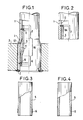
- the tube 1 is fixed to the tubular plate 2, in the usual way, by swaging, and its lower end is welded to the external face of this plate, as represented by the weld bead 3.
- the repair is carried out using an internal sleeve 5, with an external diameter slightly smaller than the internal diameter of the tube, which covers the partially corroded zone of the tube.
- This sleeve 5 is tightly connected to the tube in the two zones 6, inside the tube plate, and 7, beyond the latter and the corroded zone.
- the sleeve is first expanded in the tube in a localized manner in this zone. This expansion can take place under inert gas or with inert gas blowing.
- the welding is carried out back from the edge of the sleeve by the automatic arc arc process using an inert gas using a device for internal welding of tubes (this position allowing greater flexibility in the adjustment in altitude welding torch).
- the preliminary expansion allows the heat to be concentrated in the area to be welded, which facilitates the penetration of the weld, the removal of the metal after welding and the evacuation of the gas trapped between the tube and the sleeve.
- the weld bead must have good penetration into the thickness of the tube (from 20% to 75% thereof), but without crossing it.
- the sleeve can be provided in the region provided for the weld bead and on either side of it with a thin deposit of a metal which is not very oxidizable and which is a good conductor of heat. , such as chromium, obtained for example by metallization (deposit 14 in fig. 3). It is also possible, in order to further facilitate the evacuation of the air retained in the gap between the tube and the sleeve, to provide the lower end of the sleeve up to the level of the weld bead with fine longitudinal grooves. , for example four 90 ° grooves (grooves 15 and fig.4). The air can be evacuated either by blowing inert gas, or by vacuum, if the assembly allows.
- the upper weld is then produced after the sleeve has come into contact with the tube by controlled deformation of the diameter, by controlling the expansion of the sleeve by the number of spindle turns of a dudgeon.
- This ensures good repeatability of obtaining good contact between the tube and the sleeve, a necessary condition for ensuring good bond welding by limiting the stresses induced in the tube.
- This upper welding can also be carried out behind the edge of the sleeve, for example at 20 or 30 mm from this edge (weld bead 9 in FIG. 1). It is also possible to ensure complete fusion welding of the edge of the sleeve (weld bead 9A in FIG. 2).
- the shape of this connection allows the control of the zone 13 thermally affected by the welding and located above the welding.
- This type of weld bead is obtained by adjusting the position and the inclination of the welding electrode, that is to say by appropriate preparation of the end of the sleeve by machining.
- Welding operations can optionally be substituted by the arc under inert gas process with tungsten electrode for welding by laser beam or by electronic beam.
- the quality of the welds can be controlled by non-destructive means such as endoscopic examination, penetrant testing, eddy currents and ultrasound.
Landscapes
- Engineering & Computer Science (AREA)
- Physics & Mathematics (AREA)
- Thermal Sciences (AREA)
- Mechanical Engineering (AREA)
- General Engineering & Computer Science (AREA)
- Butt Welding And Welding Of Specific Article (AREA)
- Arc Welding In General (AREA)
Applications Claiming Priority (2)
| Application Number | Priority Date | Filing Date | Title |
|---|---|---|---|
| FR8616231A FR2607235B1 (fr) | 1986-11-21 | 1986-11-21 | Procede de reparation ou de protection d'une extremite de tube metallique d'echangeur de chaleur, et manchon pour sa mise en oeuvre |
| FR8616231 | 1986-11-21 |
Publications (2)
| Publication Number | Publication Date |
|---|---|
| EP0271739A1 true EP0271739A1 (de) | 1988-06-22 |
| EP0271739B1 EP0271739B1 (de) | 1990-10-03 |
Family
ID=9341064
Family Applications (1)
| Application Number | Title | Priority Date | Filing Date |
|---|---|---|---|
| EP87117143A Expired - Lifetime EP0271739B1 (de) | 1986-11-21 | 1987-11-20 | Verfahren zum Reparieren und Schützen eines Endes eines metallischen Wärmeaustauschrohres und Buchse zur Durchführung |
Country Status (9)
| Country | Link |
|---|---|
| US (1) | US4960650A (de) |
| EP (1) | EP0271739B1 (de) |
| JP (1) | JPS63153398A (de) |
| KR (1) | KR880006523A (de) |
| DE (1) | DE3765402D1 (de) |
| ES (1) | ES2017991B3 (de) |
| FR (1) | FR2607235B1 (de) |
| IN (1) | IN172043B (de) |
| ZA (1) | ZA878663B (de) |
Cited By (2)
| Publication number | Priority date | Publication date | Assignee | Title |
|---|---|---|---|---|
| EP0416848A1 (de) * | 1989-09-08 | 1991-03-13 | Nnc Limited | Wärmetauscher |
| FR2736989A1 (fr) * | 1995-07-19 | 1997-01-24 | Gec Alsthom Stein Ind | Dispositif destine a etre fixe de facon etanche sur au moins un element cylindrique |
Families Citing this family (12)
| Publication number | Priority date | Publication date | Assignee | Title |
|---|---|---|---|---|
| FR2652440B1 (fr) * | 1989-09-27 | 1993-12-03 | Framatome | Procede de reparation par chemisage d'un tube tel qu'un tube de generateur de vapeur. |
| US5430270A (en) * | 1993-02-17 | 1995-07-04 | Electric Power Research Institute, Inc. | Method and apparatus for repairing damaged tubes |
| US5372391A (en) * | 1993-02-22 | 1994-12-13 | The United States Of America As Represented By The United States Department Of Energy | Internal pipe attachment mechanism |
| US5392322A (en) * | 1993-11-22 | 1995-02-21 | General Electric Company | Shroud repair clamp |
| FR2726885A1 (fr) * | 1994-11-15 | 1996-05-15 | Framatome Sa | Procede de fixation resistante et etanche d'une manchette a l'interieur d'un tube metallique et manchette de reparation d'un tube metallique |
| US7551705B2 (en) * | 2003-12-11 | 2009-06-23 | Areva Np, Inc. | Fuel assembly top nozzle repair sleeve and method for repairing a fuel assembly |
| WO2005087426A1 (de) * | 2004-03-09 | 2005-09-22 | Bruendermann Georg | Verfahren zur herstellung einer wärmetauscher-trennwand mit einer aufpanzerung und wärmetauscher-trennwand |
| DE102004056619B4 (de) * | 2004-03-09 | 2007-06-06 | BRÜNDERMANN, Georg | Verfahren zur Herstellung einer Wärmetauscher-Trennwand mit einer Aufpanzerung und Wärmetauscher-Trennwand |
| US9101997B2 (en) * | 2008-09-11 | 2015-08-11 | Siemens Energy, Inc | Asymmetric heat sink welding using a penetration enhancing compound |
| US20150105212A1 (en) * | 2013-10-14 | 2015-04-16 | Caterpillar Inc. | System and method for salvaging a pin-bore assembly |
| RU2675952C2 (ru) * | 2014-01-10 | 2018-12-25 | Эуротекника Меламине, Люксембург, Цвайгнидерлассунг ин Иттиген | Трубчатый теплообменник и установка, в частности реактор для производства меламина, содержащая такой теплообменник |
| CN114182088B (zh) * | 2021-12-08 | 2023-10-13 | 中国石油大学(华东) | 降低管壳式换热器换热管与管板焊接接头应力腐蚀开裂风险的局部热处理方法 |
Citations (5)
| Publication number | Priority date | Publication date | Assignee | Title |
|---|---|---|---|---|
| US3792603A (en) * | 1972-07-26 | 1974-02-19 | Glaenzer Spicer Sa | Apparatus for assembling two parts into interlocked and interfitting relationship |
| EP0047407A1 (de) * | 1980-09-09 | 1982-03-17 | Westinghouse Electric Corporation | Auskleidungsverfahren |
| EP0112612A2 (de) * | 1982-09-30 | 1984-07-04 | The Babcock & Wilcox Company | Reparieren von undichten Rohren in Dampfgeneratoren |
| EP0121137A1 (de) * | 1983-04-04 | 1984-10-10 | Combustion Engineering, Inc. | Dichtgeschweisster Rohreinsatz |
| EP0181250A1 (de) * | 1984-11-06 | 1986-05-14 | Framatome | Muffeneinsatzverfahren zum Reparieren eines Dampferzeugerrohres und Reparaturmuffe für dieses Rohr |
Family Cites Families (18)
| Publication number | Priority date | Publication date | Assignee | Title |
|---|---|---|---|---|
| GB471413A (en) * | 1935-12-02 | 1937-09-02 | Hall & Kay Ltd | Improvements in or relating to metal sockets, bushes, ferrules, rivets and the like |
| US3064344A (en) * | 1956-09-24 | 1962-11-20 | Chicago Bridge & Iron Co | Method of producing lined vessels |
| GB1143590A (de) * | 1965-04-14 | |||
| CH581200A5 (de) * | 1974-04-27 | 1976-10-29 | Bes Sa | |
| USRE30802E (en) * | 1976-03-26 | 1981-11-24 | Combustion Engineering, Inc. | Method of securing a sleeve within a tube |
| US4028789A (en) * | 1976-03-29 | 1977-06-14 | Westinghouse Electric Corporation | Method of installing a sleeve in one end of a tube |
| US4411456A (en) * | 1976-04-02 | 1983-10-25 | Martin Charles F | Apparatus, methods, and joints for connecting tubular members |
| JPS56149596A (en) * | 1980-04-21 | 1981-11-19 | Mitsubishi Heavy Ind Ltd | Repairing method of heat transmitting fine tube for heat exchanger |
| JPS5790595A (en) * | 1980-11-27 | 1982-06-05 | Mitsubishi Heavy Ind Ltd | Repairing method of heat transfer pipe |
| JPS57196096A (en) * | 1981-05-26 | 1982-12-01 | Mitsubishi Heavy Ind Ltd | Repairing method of heat exchanger tube |
| JPS57196097A (en) * | 1981-05-26 | 1982-12-01 | Mitsubishi Heavy Ind Ltd | Repairing method of heat exchanger tube |
| US4641409A (en) * | 1982-09-23 | 1987-02-10 | Westinghouse Electric Corp. | Reconstituting a nuclear reactor fuel assembly |
| US4505017A (en) * | 1982-12-15 | 1985-03-19 | Combustion Engineering, Inc. | Method of installing a tube sleeve |
| US4513786A (en) * | 1983-04-14 | 1985-04-30 | Combustion Engineering, Inc. | Mechanical tube plub |
| US4580426A (en) * | 1984-02-27 | 1986-04-08 | Westinghouse Electric Corp. | Hybrid expansion apparatus and process |
| JPS60211289A (ja) * | 1984-04-05 | 1985-10-23 | Mitsubishi Heavy Ind Ltd | 管の補修方法 |
| US4713870A (en) * | 1985-03-26 | 1987-12-22 | Raychem Corporation | Pipe repair sleeve apparatus and method of repairing a damaged pipe |
| JP2785518B2 (ja) * | 1991-06-24 | 1998-08-13 | 日産自動車株式会社 | グローブボックスダンパーの取付構造 |
-
1986
- 1986-11-21 FR FR8616231A patent/FR2607235B1/fr not_active Expired - Lifetime
-
1987
- 1987-11-18 IN IN992/DEL/87A patent/IN172043B/en unknown
- 1987-11-19 ZA ZA878663A patent/ZA878663B/xx unknown
- 1987-11-20 JP JP62293866A patent/JPS63153398A/ja active Pending
- 1987-11-20 ES ES87117143T patent/ES2017991B3/es not_active Expired - Lifetime
- 1987-11-20 DE DE8787117143T patent/DE3765402D1/de not_active Expired - Lifetime
- 1987-11-20 EP EP87117143A patent/EP0271739B1/de not_active Expired - Lifetime
- 1987-11-21 KR KR870013146A patent/KR880006523A/ko not_active Withdrawn
-
1989
- 1989-06-15 US US07/366,362 patent/US4960650A/en not_active Expired - Fee Related
Patent Citations (5)
| Publication number | Priority date | Publication date | Assignee | Title |
|---|---|---|---|---|
| US3792603A (en) * | 1972-07-26 | 1974-02-19 | Glaenzer Spicer Sa | Apparatus for assembling two parts into interlocked and interfitting relationship |
| EP0047407A1 (de) * | 1980-09-09 | 1982-03-17 | Westinghouse Electric Corporation | Auskleidungsverfahren |
| EP0112612A2 (de) * | 1982-09-30 | 1984-07-04 | The Babcock & Wilcox Company | Reparieren von undichten Rohren in Dampfgeneratoren |
| EP0121137A1 (de) * | 1983-04-04 | 1984-10-10 | Combustion Engineering, Inc. | Dichtgeschweisster Rohreinsatz |
| EP0181250A1 (de) * | 1984-11-06 | 1986-05-14 | Framatome | Muffeneinsatzverfahren zum Reparieren eines Dampferzeugerrohres und Reparaturmuffe für dieses Rohr |
Cited By (7)
| Publication number | Priority date | Publication date | Assignee | Title |
|---|---|---|---|---|
| EP0416848A1 (de) * | 1989-09-08 | 1991-03-13 | Nnc Limited | Wärmetauscher |
| US5155894A (en) * | 1989-09-08 | 1992-10-20 | Nnc Limited | Method of repairing by lining heat exchanger tubes |
| FR2736989A1 (fr) * | 1995-07-19 | 1997-01-24 | Gec Alsthom Stein Ind | Dispositif destine a etre fixe de facon etanche sur au moins un element cylindrique |
| WO1997004268A1 (fr) * | 1995-07-19 | 1997-02-06 | Gec Alsthom Stein Industrie | Dispositif destine a etre fixe de façon etanche sur au moins un element cylindrique |
| US5924743A (en) * | 1995-07-19 | 1999-07-20 | Gec Alsthom Stein Industrie | Device adapted to be fixed and sealed to at least one cylindrical member |
| RU2157945C2 (ru) * | 1995-07-19 | 2000-10-20 | Гец Альстом Стэн Эндюстри | Устройство для герметичного крепления, по крайней мере, на одном цилиндрическом элементе |
| CN1069391C (zh) * | 1995-07-19 | 2001-08-08 | Gec阿尔松·斯坦工业公司 | 用于密封固定在至少一个圆柱形件上的装置 |
Also Published As
| Publication number | Publication date |
|---|---|
| DE3765402D1 (de) | 1990-11-08 |
| FR2607235B1 (fr) | 1990-02-16 |
| FR2607235A1 (fr) | 1988-05-27 |
| JPS63153398A (ja) | 1988-06-25 |
| IN172043B (de) | 1993-03-20 |
| US4960650A (en) | 1990-10-02 |
| EP0271739B1 (de) | 1990-10-03 |
| ZA878663B (en) | 1988-05-18 |
| KR880006523A (ko) | 1988-07-23 |
| ES2017991B3 (es) | 1991-03-16 |
Similar Documents
| Publication | Publication Date | Title |
|---|---|---|
| EP0271739B1 (de) | Verfahren zum Reparieren und Schützen eines Endes eines metallischen Wärmeaustauschrohres und Buchse zur Durchführung | |
| FR2698576A1 (fr) | Procédé et dispositif de réparation d'une zone défectueuse de la paroi d'une pièce métallique et en particulier d'une pièce tubulaire. | |
| EP0181250B1 (de) | Muffeneinsatzverfahren zum Reparieren eines Dampferzeugerrohres und Reparaturmuffe für dieses Rohr | |
| EP0477066A1 (de) | Verfahren zum Austauschen eines Rohres eines Wärmetauschers und Anwendung dieses Verfahrens | |
| EP0248728B1 (de) | Verfahren zum festen und dichten Befestigen eines hohlen, zylindrischen Elementes in das Innere eines Rohres und zylindrisches Element zur Durchführung dieses Verfahrens | |
| FR2585817A1 (fr) | Procede et dispositif de traitement de surface pour les echangeurs de chaleur | |
| FR2598209A1 (fr) | Procede et dispositif de chemisage a distance d'un tube de generateur de vapeur d'un reacteur nucleaire a eau sous pression. | |
| FR2649923A1 (fr) | Outillage de travail a l'interieur d'un element tubulaire | |
| EP0196971B1 (de) | Wiederherstellungsverfahren durch Verkleidung eines Dampfgeneratorrohres | |
| EP0699499B1 (de) | Reparaturverfahren einer heterogenen Schweissverbindung zwischen einem Stutzen eines Nuklearreaktorbestandteils und einer Rohrleitung | |
| EP0263733B1 (de) | Vorrichtung zum dichten Verschliessen einer Wanddurchführung | |
| EP0731311A1 (de) | Reparaturverfahren durch elektrolytische Verkleidung eines Rohres, insbesondere eines Dampferzeugerrohres | |
| EP0622810B1 (de) | Verfahren und Einrichtung zur Wiederherstellung und zum Rissebildungsschutz der Innenwand eines Durchführungsrohrs im Druckgefässboden eines Druckwasserkernreaktors | |
| FR2665758A1 (fr) | Procede de bouchage d'un tube d'un echangeur de chaleur a tubes droits et utilisation de ce procede. | |
| FR2652440A1 (fr) | Procede de reparation par chemisage d'un tube tel qu'un tube de generateur de vapeur. | |
| FR2723869A1 (fr) | Procede de reparation d'une liaison soudee heterogene entre une tubulure d'un composant d'un reacteur nucleaire et une tuyauterie. | |
| FR2705047A1 (fr) | Procédé et dispositif de soudage par faisceau d'électrons de deux pièces d'un composant de grande dimension et notamment d'un générateur de vapeur d'un réacteur nucléaire à eau sous pression. | |
| FR2598210A1 (fr) | Procede de reparation par soudage de tubes de generateurs de vapeur et outils correspondants. | |
| FR2799401A1 (fr) | Procede de protection et procede de renovation d'une liaison soudee heterogene entre deux elements tubulaires | |
| FR2990554A1 (fr) | Procede de reparation d'un equipement chaudronne de reacteur nucleaire | |
| FR2578957A1 (fr) | Amelioration aux generateurs de vapeur des reacteurs nucleaires | |
| FR2692972A1 (fr) | Procédé de réparation d'un tube d'échangeur de chaleur détérioré localement. | |
| FR3105555A1 (fr) | Méthode de réparation d’une enveloppe, notamment d’un pressuriseur | |
| EP0713049A1 (de) | Verfahren zum festen und dichten Befestigen einer Muffe in das Innere eines Rohres aus Metall und Reparaturmuffe für ein Rohr aus Metall | |
| JP4488591B2 (ja) | 炉心スプレイスパージャの保全方法 |
Legal Events
| Date | Code | Title | Description |
|---|---|---|---|
| PUAI | Public reference made under article 153(3) epc to a published international application that has entered the european phase |
Free format text: ORIGINAL CODE: 0009012 |
|
| AK | Designated contracting states |
Kind code of ref document: A1 Designated state(s): BE CH DE ES FR GB IT LI SE |
|
| 17P | Request for examination filed |
Effective date: 19881201 |
|
| 17Q | First examination report despatched |
Effective date: 19890803 |
|
| GRAA | (expected) grant |
Free format text: ORIGINAL CODE: 0009210 |
|
| AK | Designated contracting states |
Kind code of ref document: B1 Designated state(s): BE CH DE ES FR GB IT LI SE |
|
| GBT | Gb: translation of ep patent filed (gb section 77(6)(a)/1977) | ||
| REF | Corresponds to: |
Ref document number: 3765402 Country of ref document: DE Date of ref document: 19901108 |
|
| ITF | It: translation for a ep patent filed | ||
| PLBI | Opposition filed |
Free format text: ORIGINAL CODE: 0009260 |
|
| 26 | Opposition filed |
Opponent name: SIEMENS AG GRPA3 ERL S Effective date: 19910703 |
|
| PGFP | Annual fee paid to national office [announced via postgrant information from national office to epo] |
Ref country code: ES Payment date: 19910912 Year of fee payment: 5 |
|
| PGFP | Annual fee paid to national office [announced via postgrant information from national office to epo] |
Ref country code: CH Payment date: 19910918 Year of fee payment: 5 |
|
| PGFP | Annual fee paid to national office [announced via postgrant information from national office to epo] |
Ref country code: SE Payment date: 19910919 Year of fee payment: 5 |
|
| PGFP | Annual fee paid to national office [announced via postgrant information from national office to epo] |
Ref country code: FR Payment date: 19910930 Year of fee payment: 5 |
|
| PGFP | Annual fee paid to national office [announced via postgrant information from national office to epo] |
Ref country code: BE Payment date: 19911003 Year of fee payment: 5 |
|
| PGFP | Annual fee paid to national office [announced via postgrant information from national office to epo] |
Ref country code: DE Payment date: 19911017 Year of fee payment: 5 |
|
| PGFP | Annual fee paid to national office [announced via postgrant information from national office to epo] |
Ref country code: GB Payment date: 19911028 Year of fee payment: 5 |
|
| ITTA | It: last paid annual fee | ||
| RDAG | Patent revoked |
Free format text: ORIGINAL CODE: 0009271 |
|
| STAA | Information on the status of an ep patent application or granted ep patent |
Free format text: STATUS: PATENT REVOKED |
|
| REG | Reference to a national code |
Ref country code: CH Ref legal event code: PL |
|
| 27W | Patent revoked |
Effective date: 19920502 |
|
| GBPR | Gb: patent revoked under art. 102 of the ep convention designating the uk as contracting state | ||
| BERE | Be: lapsed |
Owner name: ELECTRICITE DE FRANCE SERVICE NATIONAL Effective date: 19921130 Owner name: STEIN INDUSTRIE Effective date: 19921130 |
|
| EUG | Se: european patent has lapsed |
Ref document number: 87117143.5 Effective date: 19920916 |
|
| PLAB | Opposition data, opponent's data or that of the opponent's representative modified |
Free format text: ORIGINAL CODE: 0009299OPPO |