EP0272047A2 - Transmission vis-écrou pivotante - Google Patents
Transmission vis-écrou pivotante Download PDFInfo
- Publication number
- EP0272047A2 EP0272047A2 EP87310839A EP87310839A EP0272047A2 EP 0272047 A2 EP0272047 A2 EP 0272047A2 EP 87310839 A EP87310839 A EP 87310839A EP 87310839 A EP87310839 A EP 87310839A EP 0272047 A2 EP0272047 A2 EP 0272047A2
- Authority
- EP
- European Patent Office
- Prior art keywords
- jacking
- screw
- ball
- screw jack
- pivotable
- Prior art date
- Legal status (The legal status is an assumption and is not a legal conclusion. Google has not performed a legal analysis and makes no representation as to the accuracy of the status listed.)
- Granted
Links
- 230000000452 restraining effect Effects 0.000 claims description 8
- 230000000295 complement effect Effects 0.000 claims description 7
- 230000000694 effects Effects 0.000 claims description 3
- 238000006073 displacement reaction Methods 0.000 description 2
- 230000000712 assembly Effects 0.000 description 1
- 238000000429 assembly Methods 0.000 description 1
- 230000004888 barrier function Effects 0.000 description 1
- 230000009977 dual effect Effects 0.000 description 1
- 230000002441 reversible effect Effects 0.000 description 1
Images
Classifications
-
- B—PERFORMING OPERATIONS; TRANSPORTING
- B60—VEHICLES IN GENERAL
- B60R—VEHICLES, VEHICLE FITTINGS, OR VEHICLE PARTS, NOT OTHERWISE PROVIDED FOR
- B60R1/00—Optical viewing arrangements; Real-time viewing arrangements for drivers or passengers using optical image capturing systems, e.g. cameras or video systems specially adapted for use in or on vehicles
- B60R1/02—Rear-view mirror arrangements
- B60R1/04—Rear-view mirror arrangements mounted inside vehicle
-
- B—PERFORMING OPERATIONS; TRANSPORTING
- B60—VEHICLES IN GENERAL
- B60R—VEHICLES, VEHICLE FITTINGS, OR VEHICLE PARTS, NOT OTHERWISE PROVIDED FOR
- B60R1/00—Optical viewing arrangements; Real-time viewing arrangements for drivers or passengers using optical image capturing systems, e.g. cameras or video systems specially adapted for use in or on vehicles
- B60R1/02—Rear-view mirror arrangements
- B60R1/06—Rear-view mirror arrangements mounted on vehicle exterior
- B60R1/062—Rear-view mirror arrangements mounted on vehicle exterior with remote control for adjusting position
- B60R1/07—Rear-view mirror arrangements mounted on vehicle exterior with remote control for adjusting position by electrically powered actuators
- B60R1/072—Rear-view mirror arrangements mounted on vehicle exterior with remote control for adjusting position by electrically powered actuators for adjusting the mirror relative to its housing
-
- Y—GENERAL TAGGING OF NEW TECHNOLOGICAL DEVELOPMENTS; GENERAL TAGGING OF CROSS-SECTIONAL TECHNOLOGIES SPANNING OVER SEVERAL SECTIONS OF THE IPC; TECHNICAL SUBJECTS COVERED BY FORMER USPC CROSS-REFERENCE ART COLLECTIONS [XRACs] AND DIGESTS
- Y10—TECHNICAL SUBJECTS COVERED BY FORMER USPC
- Y10T—TECHNICAL SUBJECTS COVERED BY FORMER US CLASSIFICATION
- Y10T74/00—Machine element or mechanism
- Y10T74/18—Mechanical movements
- Y10T74/18568—Reciprocating or oscillating to or from alternating rotary
- Y10T74/18576—Reciprocating or oscillating to or from alternating rotary including screw and nut
- Y10T74/18584—Shaft shorter than nut
-
- Y—GENERAL TAGGING OF NEW TECHNOLOGICAL DEVELOPMENTS; GENERAL TAGGING OF CROSS-SECTIONAL TECHNOLOGIES SPANNING OVER SEVERAL SECTIONS OF THE IPC; TECHNICAL SUBJECTS COVERED BY FORMER USPC CROSS-REFERENCE ART COLLECTIONS [XRACs] AND DIGESTS
- Y10—TECHNICAL SUBJECTS COVERED BY FORMER USPC
- Y10T—TECHNICAL SUBJECTS COVERED BY FORMER US CLASSIFICATION
- Y10T74/00—Machine element or mechanism
- Y10T74/18—Mechanical movements
- Y10T74/18568—Reciprocating or oscillating to or from alternating rotary
- Y10T74/18792—Reciprocating or oscillating to or from alternating rotary including worm
-
- Y—GENERAL TAGGING OF NEW TECHNOLOGICAL DEVELOPMENTS; GENERAL TAGGING OF CROSS-SECTIONAL TECHNOLOGIES SPANNING OVER SEVERAL SECTIONS OF THE IPC; TECHNICAL SUBJECTS COVERED BY FORMER USPC CROSS-REFERENCE ART COLLECTIONS [XRACs] AND DIGESTS
- Y10—TECHNICAL SUBJECTS COVERED BY FORMER USPC
- Y10T—TECHNICAL SUBJECTS COVERED BY FORMER US CLASSIFICATION
- Y10T74/00—Machine element or mechanism
- Y10T74/19—Gearing
- Y10T74/19642—Directly cooperating gears
- Y10T74/19698—Spiral
- Y10T74/19828—Worm
-
- Y—GENERAL TAGGING OF NEW TECHNOLOGICAL DEVELOPMENTS; GENERAL TAGGING OF CROSS-SECTIONAL TECHNOLOGIES SPANNING OVER SEVERAL SECTIONS OF THE IPC; TECHNICAL SUBJECTS COVERED BY FORMER USPC CROSS-REFERENCE ART COLLECTIONS [XRACs] AND DIGESTS
- Y10—TECHNICAL SUBJECTS COVERED BY FORMER USPC
- Y10T—TECHNICAL SUBJECTS COVERED BY FORMER US CLASSIFICATION
- Y10T74/00—Machine element or mechanism
- Y10T74/20—Control lever and linkage systems
- Y10T74/20207—Multiple controlling elements for single controlled element
Definitions
- This invention relates to a pivotable screw jack drive when in combination with a tilting element, for use in tilting control of position of that element, for example, of a rear vision mirror.
- the invention extends to a rear vision mirror assembly which embodies such a screw jack drive for tilting control.
- the positioning of a tiltable element relates to rotation of that element about the two principal axes, which, in most instances, are contained within a single plane.
- Such rotation can either be achieved by applying a lifting or lowering force at three or more points, or by supporting the tiltable element on a pivot point and providing two lifting or lowering forces at spaced positions which most desirably form an angle of 90° with respect to the pivot point.
- the invention is particularly useful with the latter arrangement.
- a tiltable element that would be adjusted in the above manner is a rear view mirror of a motor vehicle, and the invention is particularly applicable thereto.
- Rear view mirrors require adjustment to suit different drivers or different driving positions. Frequently, adjustment of external rear view mirrors for the required accuracy is difficult due to at least one of the mirrors being distant from the driving position. Therefore, some means for remotely adjusting the tilt of a mirror is desirable.
- the invention comprises a pivotable screw jack drive for a tiltable element such as a rear view mirror of a motor vehicle, wherein a motor driven worm wheel also performs the function of a jacking nut which rotates about a jacking screw, the projecting end of the jacking screw being connected to the tiltable element for universal pivotal movement but being restrained against relative rotation, the jacking nut being mounted in a housing with a ball joint so that the nut and screw pivot as an assembly.
- the nut has around its periphery gear teeth which define the worm wheel, for example, of cylindrical shape, and a motor has a worm which engages the gear teeth to effect rotation of the nut and consequent tilting of the tiltable element, and consequential pivoting of the nut and screw is accommodated by movement of the gear teeth across the drive worm.
- the invention consists of a combination of a tiltable element and a pivotable screw jack drive which controls tilting of the element, and which comprises a housing, a jacking nut bearing surface in a wall of the housing, a jacking nut having an outer surface which is also a bearing surface, an inner threaded surface, and a series of gear teeth spaced around its periphery defining a worm wheel, at least one of the bearing surfaces being of part spherical shape, a motor assembly within the housing having an output shaft, a drive worm on the output shaft in driving engagement with the worm wheel, a jacking screw having a first end with a threaded male portion which threadably engages said inner threaded surface of the jacking nut, and a second end which engages said element for relative pivotal movement about an axis which is perpendicular to the axis of the screw, and restraining means for restraining the screw from rotation, the arrangement being such that, upon motor rotation, the arrangement being such
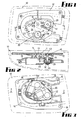
- the tiltable element of the invention is the rear vision mirror which is contained within an outer shroud 10 which is hinged in known manner to a mounting (not shown) secured to the outer surface of a motor vehicle in such a way that the shroud 10 will be displaced upon striking an obstruction.
- the invention however is not limited to such use and can be applied to other tiltable elements, or to rear vision mirrors which do not have this provision.
- the rear vision mirror 11 is carried on a mirror backing plate 12 (not shown in Fig. 3), the backing plate 12 being provided with a first ball socket 13 about which it can both universally pivot and rotate, the ball socket 13 engaging a ball 14 carried on a mounting plate 15 secured by screws 16 to the outer shroud 10.
- the requirement is to pivot the rear vision mirror 11 and its backing plate 12 with respect to the shroud, for rotation (in this embodiment) about both vertical and horizontal axes of the ball 14.
- the mounting plate 15 is provided with female lugs 20 (Fig. 3) which are engaged by protruding lugs 21 (Fig. 4) of a housing 22.
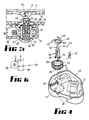
- the housing 22 contains two pivotal screw jack drives generally designated 23, and each being as shown in a larger scale in Fig. 5.
- Each screw jack drive 23 comprises an electric motor assembly 24 of the reversible type, the output shaft of which carries on it a drive worm 25.
- the housing 22 contains two part spherical hollow jacking nut bearing surfaces 27 (Fig. 4), and these are engaged by complementary part spherical bearing surfaces 28 of respective jacking nuts 29, each jacking nut 29 having an inner threaded surface 30, and a series of gear teeth 31 (which are either spur gear teeth or slightly helical to match the helix angle of the worm), the gear teeth 31 being spaced around the periphery of the jacking nut 29 to constitute a worm wheel which has a cylindrical envelope shape (that is, they are not concave teeth as with the ordinary worm wheel).
- a jacking screw 35 is bifurcate and has two limbs 36 (Fig. 4) which are splayed out by a resilient "U"-shaped spring 37, the inner ends of the limbs 36 having male threads 38 thereon which threadably engage the inner threaded surface 30 of the jacking nut 29 as best seen in Fig. 5.
- the projecting end of each jacking screw 35 passes through a soft elastomeric gasket 40 located between the housing 22 and the mounting plate 15, and terminates at its upper end in a ball head 41, the ball head 41 having a projecting spigot 42 which constitutes a restraining portion, rotation of the jacking screw being restrained by spigot 42 engaging a complementary surface of a slot 43 (Fig.
- second and third ball sockets 44 each having a slot 43 opening into it, on the underside of the backing plate 12 of the mirror 11.
- the slots are directed towards the first socket 13.
- the ball head 41 is otherwise movable within the part spherical socket 44 for the required pivotal movement in the two directions for vertical and horizontal adjustment of the position of the mirror 11.
- the arrangement therefore is such that, upon motor rotation, the worm 25 causes rotation of the jacking nut 29 to drive the jacking screw 35 outwardly or withdraw it back into the nut.
- the bifurcate limbs 36 merely spring together as the threads ride over one another, and this constitutes an in-built overload protection device.
- the backing plate 12 By driving the jacking screw 35 outwardly or withdrawing it inwardly, the backing plate 12 is tilted about the ball socket 13 in either one of the two planes, and since the ball heads 41 of the jacking screws 35 subtend an angle of 90° with each other with respect to the bolt ball socket 13, the adjustment takes place in either one of the two planes.
- tilting of the mirror 11 necessarily means that there is some tilting of the assembly of the jacking nut 29 and jacking screw 35, and this causes the gear teeth 31 to move across the thread of the worm 25 by a small degree only.
- Fig. 6 illustrates the geometry of this movement, and the displacement angle A from central position is very small (a small adjustment only being required for the mirror) and this corresponds to a distance D.
- the difference in engagement between the teeth and the threads of the worm is therefore extremely small, being trigonomically identified by (1-R cos A), wherein R is the radius of tilt, this being so small as to be negligible in the application described herein.
Landscapes
- Engineering & Computer Science (AREA)
- Multimedia (AREA)
- Mechanical Engineering (AREA)
- Rear-View Mirror Devices That Are Mounted On The Exterior Of The Vehicle (AREA)
- Transmission Devices (AREA)
- Automatic Cycles, And Cycles In General (AREA)
- Gear Transmission (AREA)
Applications Claiming Priority (2)
| Application Number | Priority Date | Filing Date | Title |
|---|---|---|---|
| AUPH949286 | 1986-12-12 | ||
| AU9492/86 | 1986-12-12 |
Publications (3)
| Publication Number | Publication Date |
|---|---|
| EP0272047A2 true EP0272047A2 (fr) | 1988-06-22 |
| EP0272047A3 EP0272047A3 (en) | 1988-07-20 |
| EP0272047B1 EP0272047B1 (fr) | 1992-04-29 |
Family
ID=3771949
Family Applications (1)
| Application Number | Title | Priority Date | Filing Date |
|---|---|---|---|
| EP87310839A Expired - Lifetime EP0272047B1 (fr) | 1986-12-12 | 1987-12-09 | Transmission vis-écrou pivotante |
Country Status (8)
| Country | Link |
|---|---|
| US (1) | US4881418A (fr) |
| EP (1) | EP0272047B1 (fr) |
| KR (1) | KR950014991B1 (fr) |
| CA (1) | CA1300944C (fr) |
| DE (1) | DE3778664D1 (fr) |
| ES (1) | ES2031524T3 (fr) |
| MY (1) | MY101786A (fr) |
| NZ (1) | NZ222870A (fr) |
Cited By (6)
| Publication number | Priority date | Publication date | Assignee | Title |
|---|---|---|---|---|
| EP0549173A1 (fr) * | 1991-12-21 | 1993-06-30 | Britax Rainsfords Pty. Limited | Assemblage de rétroviseur extérieur pour véhicule automobile |
| FR2690767A1 (fr) * | 1992-05-02 | 1993-11-05 | Bosch Gmbh Robert | Servo-mécanisme, en particulier pour le réglage du rétroviseur extérieur d'une automobile. |
| WO1995022473A1 (fr) * | 1994-02-22 | 1995-08-24 | Poong Jeong Ind. Co., Ltd. | Dispositif de reglage de l'angle d'inclinaison du retroviseur exterieur d'un vehicule automobile |
| EP0713804A1 (fr) | 1994-11-26 | 1996-05-29 | Britax (Geco) S.A. | Rétroviseur extérieur pour véhicule |
| EP0979757A2 (fr) | 1998-08-08 | 2000-02-16 | Britax Rainsfords Pty. Limited | Rétroviseur |
| US6050537A (en) * | 1997-02-06 | 2000-04-18 | Britax Rainsfords Pty. Limited | Mirror carrier mounting arrangement for a vehicle rear view mirror |
Families Citing this family (20)
| Publication number | Priority date | Publication date | Assignee | Title |
|---|---|---|---|---|
| WO1991018758A1 (fr) * | 1990-05-29 | 1991-12-12 | Ichikoh Industries, Ltd. | Retroviseur a telecommande electrique |
| US5226034A (en) * | 1990-06-19 | 1993-07-06 | Ichikoh Industries, Ltd. | Electrically remote-controlled type mirror assembly |
| US5293784A (en) * | 1991-09-06 | 1994-03-15 | Gebruder Buhler Nachfolger Gmbh | Drive device for a vehicle rear-view mirror |
| US5331471A (en) * | 1991-10-04 | 1994-07-19 | Britax Rainsfords Pty Ltd | Discrete mirror drive assembly |
| AU652078B2 (en) * | 1991-10-04 | 1994-08-11 | Visiocorp Patents S.A.R.L. | Discrete mirror drive assembly |
| US5363246A (en) * | 1993-05-12 | 1994-11-08 | United Technologies Automotive, Inc. | Power pack for an automotive exterior mirror assembly |
| NL9401791A (nl) * | 1994-10-27 | 1996-06-03 | Iku Holding Montfoort Bv | Verplaatsingsinstelinrichting. |
| US5701211A (en) * | 1995-03-31 | 1997-12-23 | United Technologies Automotive Systems, Inc. | Vehicle mirror adjustment gear train |
| US5782686A (en) * | 1995-12-04 | 1998-07-21 | Cummins-Allison Corp. | Disc coin sorter with slotted exit channels |
| US5959790A (en) * | 1997-01-14 | 1999-09-28 | Harman Automotive, Inc. | Breakaway mirror construction and method of assembly |
| US5926331A (en) * | 1997-01-30 | 1999-07-20 | Harman Automotive, Inc. | Power pack for controlling the angular position of a vehicle rearview mirror |
| US6555222B1 (en) | 2000-01-13 | 2003-04-29 | Schefenacker Vision Systems France Sa | Reinforced polypropylene mirror assembly and process for making the same |
| WO2003003776A2 (fr) | 2001-06-27 | 2003-01-09 | Nortel Networks Limited | Mise en correspondance d'informations dans des systemes de radiocommunication |
| US6485155B1 (en) * | 2001-07-06 | 2002-11-26 | Bernard Duroux | Multiplexing mirror |
| AU2003253938A1 (en) * | 2002-07-19 | 2004-02-09 | Magna Donnelly North America, L.L.C. | Rear view mirror with snap connection |
| US7080914B1 (en) | 2003-02-27 | 2006-07-25 | Magna Donnelly Mirrors North America L.L.C. | Vehicular mirror with adjustable pivot connection |
| US7090363B1 (en) | 2003-02-27 | 2006-08-15 | Magna Donnelly Mirrors North America L.L.C. | Mirror actuator assembly with modular positional memory device |
| US9976646B2 (en) * | 2015-05-28 | 2018-05-22 | Automotive Research & Testing Center | Angle regulation device |
| CN109911809A (zh) * | 2019-01-22 | 2019-06-21 | 福建(泉州)哈工大工程技术研究院 | 一种旋转顶升机构及包含该旋转顶升机构的潜伏式agv |
| CN113479821A (zh) * | 2021-06-11 | 2021-10-08 | 广东兴发铝业有限公司 | 一种铝型材仓储用运输升降机 |
Family Cites Families (8)
| Publication number | Priority date | Publication date | Assignee | Title |
|---|---|---|---|---|
| US2311972A (en) * | 1941-03-24 | 1943-02-23 | Gen Motors Corp | Power operated window regulator |
| US3069924A (en) * | 1959-08-18 | 1962-12-25 | Nippon Light Metal Co | Screw jack |
| US3978735A (en) * | 1974-05-16 | 1976-09-07 | Tenna Corporation | Electrically adjustable vehicle accessory |
| JPS6058054B2 (ja) * | 1981-02-24 | 1985-12-18 | 株式会社 村上開明堂 | 電動式ミラ−駆動装置 |
| FR2526737B1 (fr) * | 1982-05-13 | 1986-04-25 | Manzoni Stephane | Dispositif limiteur de couple pour mecanisme de commande d'un miroir de retroviseur |
| FR2545768B2 (fr) * | 1982-05-13 | 1987-12-04 | Manzoni Stephane | Dispositif limiteur de couple pour mecanisme de commande d'un miroir de retroviseur |
| US4482211A (en) * | 1982-12-13 | 1984-11-13 | Robert J. Fisher | Electrically operated remote control rearview mirror |
| US4509382A (en) * | 1983-03-25 | 1985-04-09 | General Motors Corporation | Preloaded screw actuator |
-
1987
- 1987-12-08 US US07/130,265 patent/US4881418A/en not_active Ceased
- 1987-12-09 EP EP87310839A patent/EP0272047B1/fr not_active Expired - Lifetime
- 1987-12-09 ES ES198787310839T patent/ES2031524T3/es not_active Expired - Lifetime
- 1987-12-09 DE DE8787310839T patent/DE3778664D1/de not_active Expired - Lifetime
- 1987-12-09 CA CA000553896A patent/CA1300944C/fr not_active Expired - Lifetime
- 1987-12-10 NZ NZ222870A patent/NZ222870A/en unknown
- 1987-12-12 MY MYPI87003189A patent/MY101786A/en unknown
- 1987-12-12 KR KR1019870014211A patent/KR950014991B1/ko not_active Expired - Fee Related
Cited By (9)
| Publication number | Priority date | Publication date | Assignee | Title |
|---|---|---|---|---|
| EP0549173A1 (fr) * | 1991-12-21 | 1993-06-30 | Britax Rainsfords Pty. Limited | Assemblage de rétroviseur extérieur pour véhicule automobile |
| US5436769A (en) * | 1991-12-21 | 1995-07-25 | Britax Rainsfords Pty. Limited | Rear view mirror assembly for motor vehicle |
| FR2690767A1 (fr) * | 1992-05-02 | 1993-11-05 | Bosch Gmbh Robert | Servo-mécanisme, en particulier pour le réglage du rétroviseur extérieur d'une automobile. |
| WO1995022473A1 (fr) * | 1994-02-22 | 1995-08-24 | Poong Jeong Ind. Co., Ltd. | Dispositif de reglage de l'angle d'inclinaison du retroviseur exterieur d'un vehicule automobile |
| EP0713804A1 (fr) | 1994-11-26 | 1996-05-29 | Britax (Geco) S.A. | Rétroviseur extérieur pour véhicule |
| US5828504A (en) * | 1994-11-26 | 1998-10-27 | Britax (Geco) S.A. | Exterior rearview mirror for a vehicle |
| US6050537A (en) * | 1997-02-06 | 2000-04-18 | Britax Rainsfords Pty. Limited | Mirror carrier mounting arrangement for a vehicle rear view mirror |
| USRE39328E1 (en) * | 1997-02-06 | 2006-10-10 | Schefenacker Vision Systems Australia Pty Ltd. | Mirror carrier mounting arrangement for a vehicle rear view mirror |
| EP0979757A2 (fr) | 1998-08-08 | 2000-02-16 | Britax Rainsfords Pty. Limited | Rétroviseur |
Also Published As
| Publication number | Publication date |
|---|---|
| CA1300944C (fr) | 1992-05-19 |
| KR880007297A (ko) | 1988-08-26 |
| AU602373B2 (en) | 1990-10-11 |
| EP0272047A3 (en) | 1988-07-20 |
| KR950014991B1 (ko) | 1995-12-21 |
| ES2031524T3 (es) | 1992-12-16 |
| AU8223587A (en) | 1988-06-16 |
| EP0272047B1 (fr) | 1992-04-29 |
| MY101786A (en) | 1992-01-17 |
| NZ222870A (en) | 1990-06-26 |
| DE3778664D1 (de) | 1992-06-04 |
| US4881418A (en) | 1989-11-21 |
Similar Documents
| Publication | Publication Date | Title |
|---|---|---|
| US4881418A (en) | Pivotable screw jack drive | |
| US4482211A (en) | Electrically operated remote control rearview mirror | |
| CA1325351C (fr) | Retroviseur de vehicule | |
| CN1050574C (zh) | 改进的双转动后视镜组件 | |
| US5740699A (en) | Wrist joint which is longitudinally extendible | |
| US5572376A (en) | Extensible vehicle mirror | |
| EP0485620B1 (fr) | Retroviseur a telecommande electrique | |
| USRE34142E (en) | Pivotable screw jack drive | |
| US4824232A (en) | Drive system with resilient yieldable biased actuator shaft for electric rear view mirror | |
| US6164148A (en) | Motorized actuator for vehicle wing mirrors | |
| US5836462A (en) | Adjusting means | |
| EP0463563A1 (fr) | Rétroviseur à commande à distance électrique | |
| WO1995022473A1 (fr) | Dispositif de reglage de l'angle d'inclinaison du retroviseur exterieur d'un vehicule automobile | |
| US5209140A (en) | Windshield wiper apparatus having a retraction facility | |
| CA1229755A (fr) | Retroviseur a telecommande electrique | |
| JPH0356207B2 (fr) | ||
| JPS6047129B2 (ja) | 車両用後写鏡装置 | |
| EP0265973A1 (fr) | Dispositif de réglage pour rétroviseur | |
| CN111661131B (zh) | 一种自动回位的电子方向盘 | |
| JPH0425902B2 (fr) | ||
| JPH05124470A (ja) | スピンドルを調節するための装置 | |
| JPH0526638U (ja) | 電動式リモートコントロールミラー | |
| DE2117620B2 (de) | Halterung für Kraftfahrzeug Außen rückblickspiegel | |
| JP2562034Y2 (ja) | バックミラーの角度制御機構 | |
| JPH04243640A (ja) | 電動式リモートコントロールミラー |
Legal Events
| Date | Code | Title | Description |
|---|---|---|---|
| PUAI | Public reference made under article 153(3) epc to a published international application that has entered the european phase |
Free format text: ORIGINAL CODE: 0009012 |
|
| PUAL | Search report despatched |
Free format text: ORIGINAL CODE: 0009013 |
|
| AK | Designated contracting states |
Kind code of ref document: A2 Designated state(s): DE ES FR GB |
|
| AK | Designated contracting states |
Kind code of ref document: A3 Designated state(s): DE ES FR GB |
|
| 17P | Request for examination filed |
Effective date: 19881221 |
|
| 17Q | First examination report despatched |
Effective date: 19910510 |
|
| GRAA | (expected) grant |
Free format text: ORIGINAL CODE: 0009210 |
|
| AK | Designated contracting states |
Kind code of ref document: B1 Designated state(s): DE ES FR GB |
|
| REF | Corresponds to: |
Ref document number: 3778664 Country of ref document: DE Date of ref document: 19920604 |
|
| ET | Fr: translation filed | ||
| REG | Reference to a national code |
Ref country code: ES Ref legal event code: FG2A Ref document number: 2031524 Country of ref document: ES Kind code of ref document: T3 |
|
| PLBE | No opposition filed within time limit |
Free format text: ORIGINAL CODE: 0009261 |
|
| STAA | Information on the status of an ep patent application or granted ep patent |
Free format text: STATUS: NO OPPOSITION FILED WITHIN TIME LIMIT |
|
| 26N | No opposition filed | ||
| PGFP | Annual fee paid to national office [announced via postgrant information from national office to epo] |
Ref country code: ES Payment date: 20001220 Year of fee payment: 14 |
|
| REG | Reference to a national code |
Ref country code: GB Ref legal event code: IF02 |
|
| PG25 | Lapsed in a contracting state [announced via postgrant information from national office to epo] |
Ref country code: ES Free format text: LAPSE BECAUSE OF NON-PAYMENT OF DUE FEES Effective date: 20021210 |
|
| PGFP | Annual fee paid to national office [announced via postgrant information from national office to epo] |
Ref country code: GB Payment date: 20031105 Year of fee payment: 17 |
|
| PGFP | Annual fee paid to national office [announced via postgrant information from national office to epo] |
Ref country code: DE Payment date: 20031230 Year of fee payment: 17 |
|
| REG | Reference to a national code |
Ref country code: ES Ref legal event code: FD2A Effective date: 20030113 |
|
| PG25 | Lapsed in a contracting state [announced via postgrant information from national office to epo] |
Ref country code: GB Free format text: LAPSE BECAUSE OF NON-PAYMENT OF DUE FEES Effective date: 20041209 |
|
| PG25 | Lapsed in a contracting state [announced via postgrant information from national office to epo] |
Ref country code: DE Free format text: LAPSE BECAUSE OF NON-PAYMENT OF DUE FEES Effective date: 20050701 |
|
| GBPC | Gb: european patent ceased through non-payment of renewal fee |
Effective date: 20041209 |
|
| PGFP | Annual fee paid to national office [announced via postgrant information from national office to epo] |
Ref country code: FR Payment date: 20051201 Year of fee payment: 19 |
|
| REG | Reference to a national code |
Ref country code: FR Ref legal event code: ST Effective date: 20070831 |
|
| PG25 | Lapsed in a contracting state [announced via postgrant information from national office to epo] |
Ref country code: FR Free format text: LAPSE BECAUSE OF NON-PAYMENT OF DUE FEES Effective date: 20070102 |