EP0272108A2 - Dispositif mesureur pour la vitesse rotatif d'une transmission à variation de vitesse infinie - Google Patents
Dispositif mesureur pour la vitesse rotatif d'une transmission à variation de vitesse infinie Download PDFInfo
- Publication number
- EP0272108A2 EP0272108A2 EP87311092A EP87311092A EP0272108A2 EP 0272108 A2 EP0272108 A2 EP 0272108A2 EP 87311092 A EP87311092 A EP 87311092A EP 87311092 A EP87311092 A EP 87311092A EP 0272108 A2 EP0272108 A2 EP 0272108A2
- Authority
- EP
- European Patent Office
- Prior art keywords
- oil
- pitot tube
- groove
- annular
- detecting device
- Prior art date
- Legal status (The legal status is an assumption and is not a legal conclusion. Google has not performed a legal analysis and makes no representation as to the accuracy of the status listed.)
- Granted
Links
Images


Classifications
-
- F—MECHANICAL ENGINEERING; LIGHTING; HEATING; WEAPONS; BLASTING
- F16—ENGINEERING ELEMENTS AND UNITS; GENERAL MEASURES FOR PRODUCING AND MAINTAINING EFFECTIVE FUNCTIONING OF MACHINES OR INSTALLATIONS; THERMAL INSULATION IN GENERAL
- F16H—GEARING
- F16H59/00—Control inputs to control units of change-speed- or reversing-gearings for conveying rotary motion
- F16H59/36—Inputs being a function of speed
- F16H59/38—Inputs being a function of speed of gearing elements
-
- F—MECHANICAL ENGINEERING; LIGHTING; HEATING; WEAPONS; BLASTING
- F16—ENGINEERING ELEMENTS AND UNITS; GENERAL MEASURES FOR PRODUCING AND MAINTAINING EFFECTIVE FUNCTIONING OF MACHINES OR INSTALLATIONS; THERMAL INSULATION IN GENERAL
- F16H—GEARING
- F16H61/00—Control functions within control units of change-speed- or reversing-gearings for conveying rotary motion ; Control of exclusively fluid gearing, friction gearing, gearings with endless flexible members or other particular types of gearing
- F16H61/66—Control functions within control units of change-speed- or reversing-gearings for conveying rotary motion ; Control of exclusively fluid gearing, friction gearing, gearings with endless flexible members or other particular types of gearing specially adapted for continuously variable gearings
- F16H61/662—Control functions within control units of change-speed- or reversing-gearings for conveying rotary motion ; Control of exclusively fluid gearing, friction gearing, gearings with endless flexible members or other particular types of gearing specially adapted for continuously variable gearings with endless flexible members
- F16H61/66231—Control functions within control units of change-speed- or reversing-gearings for conveying rotary motion ; Control of exclusively fluid gearing, friction gearing, gearings with endless flexible members or other particular types of gearing specially adapted for continuously variable gearings with endless flexible members controlling shifting exclusively as a function of speed
- F16H61/6624—Control functions within control units of change-speed- or reversing-gearings for conveying rotary motion ; Control of exclusively fluid gearing, friction gearing, gearings with endless flexible members or other particular types of gearing specially adapted for continuously variable gearings with endless flexible members controlling shifting exclusively as a function of speed using only hydraulical and mechanical sensing or control means
-
- F—MECHANICAL ENGINEERING; LIGHTING; HEATING; WEAPONS; BLASTING
- F16—ENGINEERING ELEMENTS AND UNITS; GENERAL MEASURES FOR PRODUCING AND MAINTAINING EFFECTIVE FUNCTIONING OF MACHINES OR INSTALLATIONS; THERMAL INSULATION IN GENERAL
- F16H—GEARING
- F16H61/00—Control functions within control units of change-speed- or reversing-gearings for conveying rotary motion ; Control of exclusively fluid gearing, friction gearing, gearings with endless flexible members or other particular types of gearing
- F16H61/66—Control functions within control units of change-speed- or reversing-gearings for conveying rotary motion ; Control of exclusively fluid gearing, friction gearing, gearings with endless flexible members or other particular types of gearing specially adapted for continuously variable gearings
- F16H61/662—Control functions within control units of change-speed- or reversing-gearings for conveying rotary motion ; Control of exclusively fluid gearing, friction gearing, gearings with endless flexible members or other particular types of gearing specially adapted for continuously variable gearings with endless flexible members
- F16H61/66254—Control functions within control units of change-speed- or reversing-gearings for conveying rotary motion ; Control of exclusively fluid gearing, friction gearing, gearings with endless flexible members or other particular types of gearing specially adapted for continuously variable gearings with endless flexible members controlling of shifting being influenced by a signal derived from the engine and the main coupling
- F16H61/66263—Control functions within control units of change-speed- or reversing-gearings for conveying rotary motion ; Control of exclusively fluid gearing, friction gearing, gearings with endless flexible members or other particular types of gearing specially adapted for continuously variable gearings with endless flexible members controlling of shifting being influenced by a signal derived from the engine and the main coupling using only hydraulical and mechanical sensing or control means
Definitions
- the present invention relates to a rotational speed detecting device for a continuously variable belt-drive transmission for a motor vehicle, and more particularly to a device using a pitot tube for measuring a pitot pressure of an oil stream in a drive pulley of the continuously variable belt transmission.
- Japanese Patent Application Laid Open 60-104852 discloses a speed measuring system in which a pitot tube is provided under oil in an annular groove formed on one side of a drive pulley which is connected an output shaft of an engine. When the drive pulley is rotated, the oil in the groove is rotated with the pulley.
- the system detects the total pressure (pitot pressure) of the oil stream for controlling the transmission ratio and the line pressure in a CVT.
- pitot pressure total pressure of the oil stream for controlling the transmission ratio and the line pressure in a CVT.
- an inlet of the pitot tube has a large opening area in order to measure the pitot pressure with accuracy.
- the pitot tube is formed to have a cylindrical shape having a round inlet.
- the round end of the pitot tube obstructs the groove to generate the turbulence of the oil.
- the turbulent flow inducts air in the oil to form bubbles.
- the air in the oil causes the pitot pressure to fluctuate. Accordingly, it is disadvantageous to increase the opening area of the inlet.
- the present invention seeks to provide a rotational speed detecting device by which pitot pressure can be accurately and stably measured.
- a rotational speed detecting device for a continuously variable transmission having a drive pulley comprising: an annular housing securable to a side of the drive pulley and forming an annular groove, a pitot tube in the annular groove and an oil supply pipe for supply oil in to the groove, whereby when the annular housing is rotated oil supplied into the annular groove can impinge on the pitot tube, characterised in that the pitot tube has an elliptic section, the major axis of the ellipse is arranged in a substantially tangential direction of an annular flow of oil in the groove, and an open end of pitot tube faces the flow of the oil.
- the open end is formed by obliquely cutting the pitot tube, and the oil supply pipe is disposed in a downstream position with respect to the pitot tube.
- a continuously variable transmission comprises: a rotatable drive pulley, an annular housing secured to a side of the drive pulley and forming an annular groove, a pitot tube in the annular groove and an oil supply pipe for supply oil in to the groove, so that when the annular housing is rotated oil supplied in to the annular groove can impinge on the pitot tube characterised in that the pitot tube has an elliptic section, the major axis of the ellipse is arranged in a substantially tangential direction of an annular flow of oil in the groove, and an open end of pitot tube faces the flow of the oil.
- a continuously variable belt-device automatic transmission for a vehicle comprises an electromagnetic powder clutch 1, a continuously variable belt-drive transmission 2 (called hereinafter CVT).
- the CVT 2 has a selector device 3, pulley and belt device 4, and final reduction device 5.
- the electromagnetic powder clutch 1 is provided in a housing 6, and the selector device 3, pulleys and belt device 4 and final reduction device 5 are provided in a main housing 7 and a side housing 8.
- a crankshaft 10 of an engine (not shown) is connected to an annular drive member 12 through a drive plate 11 of the electromagnetic powder clutch 1.
- the electromagnetic powder clutch 1 comprises a driven member 14, a magnetizing coil 15 provided in the driven member 14.
- the driven member 14 has its outer periphery spaced from the inner periphery of the drive member 12 by a gap 16, and a powder chamber 17 is defined between the drive member 12 and driven member 14. Powder of magnetic material is provided in the powder chamber 17.
- the driven member 14 is secured to an input shaft 13 of the CVT 2.
- a holder secured to the driven member 14 carries slip rings 18 which are electrically connected to the coil 15.
- the coil 15 is supplied through brushes 19 and slip rings 18 with current from a control circuit for the electromagnetic powder clutch.
- driven member 14 When the magnetizing coil 15 is excited by the clutch current, driven member 14 is magnetized to produce a magnetic flux passing through the drive member 12. The magnetic powder is aggregated in the gap 16 by the magnetic flux and the driven member 14 is engaged with the drive member 12 by the powder. On the other hand, when the clutch current is cut off, the drive and driven members 12 and 14 are disengaged from one another.
- the selector device 3 is provided between the input shaft 13 and a main shaft 20.
- the main shaft 20 is cylindrical and is disposed coaxially with the input shaft 13.
- the selector device 3 comprises a drive gear 21 integral with input shaft 13, reverse driven gear 22 rotatably mounted on the main shaft 20, and a synchronizer 27 as a synchromesh mechanism, which is mounted on the main shaft 20.
- the drive gear 21 meshes with one of counter gears 24 rotatably mounted on a shaft 23.
- Another gear of the counter gears 24 engages with an idler gear 26 rotatably mounted on a shaft 25, which in turn engages with the driven gear 22.
- the synchronizer 27 comprises a hub 28 secured to the main shaft 20, a synchronizer sleeve 29 slidably engaged with the hub 28 with splines, and synchronizer rings 30 and 31.
- the synchronizer sleeve 29 is adapted to engage with splines of the drive gear 21 or with splines of driven gear 22 through rings 30 or 31.
- the sleeve 29 does not engage either gear, so that the main shaft 20 is disconnected from the input shaft 13.
- N range neutral position
- P range parking position
- the input shaft 13 is connected to the main shaft 20 through the gear 21 and synchronizer 27 to provide driving positions.
- the input shaft 13 is connected to the main shaft 20 through gears 21, 24, 26 and 22 to provide a reverse driving position.
- the main shaft 20 has an axial passage in which an oil pump driving shaft 42 connected to crankshaft 10 is mounted.
- An output shaft 35 is provided in parallel with the main shaft 20.
- a drive pulley 36 and a driven pulley 37 are mounted on shafts 20 and 35.
- a fixed conical disc 36a of the drive pulley 36 is integral with main shaft 20 and an axially movable conical disc 36b is axially slidably mounted on the main shaft 20.
- the movable conical disc 36b also slides in a cylinder 38b secured to the main shaft 20 to form a servo device 38.
- a chamber 38a of the servo device 38 communicates with an oil pump 41 through a pressure oil control circuit (not shown). The oil pump 41 is driven by the shaft 42.
- a pitot pressure detecting device 50 is mounted on the cylinder 38b of the servo device 38 for detecting a rotating speed for the CVT 2 as described hereinafter.
- a fixed conical disc 37a of the driven pulley 37 is formed on the output shaft 35 opposite the movable disc 36b and a movable conical disc 37b is slidably mounted on the shaft 35 opposite disc 36a.
- Movable conical disc 37b has a cylindrical portion in which a piston portion of the output shaft 35 is slidably engaged to form a servo device 39.
- a chamber 39a of the servo device 39 is communicated with the oil pump 41 through the pressure oil control circuit.
- a spring 40 is provided to urge the movable conical disc 37b to the fixed conical disc 37a.
- a drive belt 34 engages with the drive pulley 36 and the driven pulley 37.
- a drive gear 43 Secured to the output shaft 35 is a drive gear 43 which engages with an intermediate reduction gear 44a on an intermediate shaft 44.
- An intermediate gear 45 on the shaft 44 engages with a final gear 46. Rotation of the final gear 46 is transmitted to axles 48 and 49 of the vehicle driving wheels through a differential 47.
- the pitot pressure detecting device 50 comprises an annular housing 51 secured to the cylinder 38b of the servo device 38 at a base thereof by rivets 52.
- the annular housing 51 has a U-shaped section for defining an annular groove 53 for holding the oil.
- the housing 51 is disposed adjacent the side housing 8 in such a position that an annular periphery 51a of the housing 51 is opposed to an annular projecting portion 8b of the side housing 8 with a space ⁇ there-between.
- the oil charged in the groove 53 is overflowed from the periphery 51a through the space ⁇ so that the oil level is positioned lower than the periphery 51a.
- a support pipe 54 for supporting a pitot tube 55 is mounted on the projecting portion 8b.
- the pitot tube 55 having a detect hole 55a is secured to the support pipe 54 at a projected end portion thereof to be disposed in the groove 53.
- the pitot tube is arranged in the radial direction.
- the pitot tube 55 communicates with an oil passage 56 of the side housing 8 through a hole 54a of the support pipe 54.
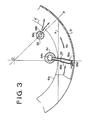
- the oil in the groove 53 is retained in a lower portion thereof.
- the surface of the oil coincides with the periphery 51a of the housing 51 as indicated by A of Fig. 3.
- the pitot tube 55 has an upper cylindrical portion 55b an end of which is secured to the support pipe 54 and a lower elliptic portion 55c which is plunged in the oil in the groove 53.
- An end of the lower elliptic portion 55c is obliquely cut off to form an elliptic open end 55d having a predetermined angle ⁇ with respect to the axis of the pitot tube 55.
- a cut 55e has a streamline as shown in Fig. 5.
- the pitot tube 55 is so disposed that the major axis of the elliptic portion 55c extends in the tangential direction of the annular flow of oil and that the open end 55d faces the flow of oil.
- the elliptic portion 55c can be formed by inserting a pin having a predetermined diameter into a pipe and pressing the pipe.
- An oil supply pipe 58 is inserted into a hold 57 formed in the projecting portion 8b by force fit.
- the oil supply pipe 58 has an axial hole 58a communicated with a lubricating oil passage 59 formed in the wall 8a of the side housing 8 and a supply port 58b formed in the pipe 58.
- the supply pipe 58 is disposed downstream of the flow of oil with respect to the pitot tube 55.
- the axis of the supply port 58b is slightly inclined with respect to a radial line O-P passing a rotating center O of the drive pulley 36 and the axis of the oil supply pipe 58 so as to discharge the oil in a downstream direction from the supply pipe.
- supply port 58b is inclined toward a wall 51b of the housing 51, as shown in Fig. 2.
- the operation of the oil pump 41 stops and the supply of the oil stops.
- the oil in the groove 53 remains at the lowest level as indicated by A of Fig. 3.
- the inlet 55d of the pitot tube 55 is under to oil, so that the oil prevents air from entering into the pitot tube 55.
- the oil pump 41 is operated by the oil pump driving shaft 42 which is connected to the crankshaft 10.
- the oil is fed to the supply pipe 58 through the passage 59 and discharged from the supply port 58b toward the wall 51b and in the flowing direction of the oil.
- the oil pressure is not applied to the pitot tube 55.
- a minimum pitot pressure is detected.
- the pitot tube Since the pitot tube has an elliptic section which is arranged in the flowing direction of the oil, turbulence of the flow does not occur. Further, the pitot tube has a large opening area because of the obliquely cut end. Since the supply pipe is disposed in a downstream portion with respect to the pitot tube, the pitot pressure is not affected by the oil supply.
- the turbulence of oil in the groove 53 is kept minimum, even if a large amount of oil is discharged at high rotating speed.
- the present invention provides a pitot pressure detecting device for detecting a rotating speed which may effectively prevent the turburence of the flowing oil in the groove. Therefore, pitot pressure is stably obtained with accuracy.
Landscapes
- Engineering & Computer Science (AREA)
- General Engineering & Computer Science (AREA)
- Mechanical Engineering (AREA)
- Transmissions By Endless Flexible Members (AREA)
- Control Of Transmission Device (AREA)
Applications Claiming Priority (4)
| Application Number | Priority Date | Filing Date | Title |
|---|---|---|---|
| JP30063586A JPS63152758A (ja) | 1986-12-17 | 1986-12-17 | 無段変速機のピト−圧検出装置 |
| JP30063486A JPS63152757A (ja) | 1986-12-17 | 1986-12-17 | 無段変速機のピト−圧検出装置 |
| JP300635/86 | 1986-12-17 | ||
| JP300634/86 | 1986-12-17 |
Publications (3)
| Publication Number | Publication Date |
|---|---|
| EP0272108A2 true EP0272108A2 (fr) | 1988-06-22 |
| EP0272108A3 EP0272108A3 (en) | 1990-04-04 |
| EP0272108B1 EP0272108B1 (fr) | 1993-03-24 |
Family
ID=26562399
Family Applications (1)
| Application Number | Title | Priority Date | Filing Date |
|---|---|---|---|
| EP87311092A Expired - Lifetime EP0272108B1 (fr) | 1986-12-17 | 1987-12-16 | Dispositif mesureur pour la vitesse rotatif d'une transmission à variation de vitesse infinie |
Country Status (3)
| Country | Link |
|---|---|
| US (1) | US4784630A (fr) |
| EP (1) | EP0272108B1 (fr) |
| DE (1) | DE3785011T2 (fr) |
Cited By (3)
| Publication number | Priority date | Publication date | Assignee | Title |
|---|---|---|---|---|
| EP0489999A1 (fr) * | 1990-12-13 | 1992-06-17 | Mitsuboshi Belting Ltd. | Variateur continu de vitesse à courroie avec dispositif de poulie à vitesse variable |
| EP0498210A1 (fr) * | 1991-01-22 | 1992-08-12 | Honda Giken Kogyo Kabushiki Kaisha | Système de commande pour une transmission continue de vitesses |
| EP1423612A4 (fr) * | 2001-09-07 | 2009-05-27 | Envirotech Pumpsystems Inc | Piece rapportee perfectionnee tube de pitot |
Families Citing this family (10)
| Publication number | Priority date | Publication date | Assignee | Title |
|---|---|---|---|---|
| US5073147A (en) * | 1989-03-30 | 1991-12-17 | Mitsuboshi Belting, Ltd. | Belt-type continuously variable transmission with variable-speed pulley mechanism |
| NL8902766A (nl) * | 1989-11-08 | 1991-06-03 | Doornes Transmissie Bv | Aandrijfsysteem voor hulpapparatuur. |
| US6093125A (en) * | 1998-03-19 | 2000-07-25 | Ford Global Technologies, Inc. | All wheel drive continuously variable transmission having dual mode operation |
| US5888161A (en) * | 1998-03-19 | 1999-03-30 | Ford Global Technologies, Inc. | All wheel drive continuously variable transmission having dual mode operation |
| US5941789A (en) * | 1998-03-19 | 1999-08-24 | Ford Global Technologies, Inc. | All wheel drive continuously variable transmission having dual mode operation |
| US5916053A (en) * | 1998-03-19 | 1999-06-29 | Ford Global Technologies, Inc. | Dual mode operation continuously variable transmission having creeper low and reverse gears |
| US5937711A (en) * | 1998-03-19 | 1999-08-17 | Ford Global Technologies, Inc. | All wheel drive continuously variable transmission having dual mode operation |
| US6106428A (en) * | 1998-03-23 | 2000-08-22 | Ford Global Technologies, Inc. | Compact dual mode continually variable transmission |
| US8246313B2 (en) * | 2009-06-29 | 2012-08-21 | Westinghouse Electric Company Llc | Dynamic port for measuring reactor coolant pump bearing oil level |
| DE102010021894B4 (de) * | 2010-05-28 | 2015-07-09 | Zf Friedrichshafen Ag | Verfahren und Einrichtung zur Innenbeölung einer koaxial zur Ölpumpe eines Getriebes angeordneten und die Ölpumpe antreibenden Getriebewelle |
Family Cites Families (6)
| Publication number | Priority date | Publication date | Assignee | Title |
|---|---|---|---|---|
| NL165821C (nl) * | 1976-02-09 | 1981-05-15 | Doornes Transmissie Bv | Traploos variabele overbrenging. |
| JPS59106754A (ja) * | 1982-12-09 | 1984-06-20 | Nissan Motor Co Ltd | Vベルト式無段変速機の油圧制御装置 |
| US4583423A (en) * | 1983-02-24 | 1986-04-22 | Ford Motor Company | Infinitely variable transmission for automotive vehicle driveline |
| JPS60104852A (ja) * | 1983-11-10 | 1985-06-10 | Mazda Motor Corp | ベルト式無段変速機 |
| DE3438201A1 (de) * | 1984-10-18 | 1986-04-24 | Rudolf 8580 Bayreuth Brözel | Sonde zur bestimmung des statischen druckes in einer stroemung |
| US4622850A (en) * | 1985-05-10 | 1986-11-18 | Gaffrig James W | Marine pitot tube |
-
1987
- 1987-12-10 US US07/130,882 patent/US4784630A/en not_active Expired - Lifetime
- 1987-12-16 EP EP87311092A patent/EP0272108B1/fr not_active Expired - Lifetime
- 1987-12-16 DE DE8787311092T patent/DE3785011T2/de not_active Expired - Fee Related
Cited By (4)
| Publication number | Priority date | Publication date | Assignee | Title |
|---|---|---|---|---|
| EP0489999A1 (fr) * | 1990-12-13 | 1992-06-17 | Mitsuboshi Belting Ltd. | Variateur continu de vitesse à courroie avec dispositif de poulie à vitesse variable |
| EP0498210A1 (fr) * | 1991-01-22 | 1992-08-12 | Honda Giken Kogyo Kabushiki Kaisha | Système de commande pour une transmission continue de vitesses |
| US5183439A (en) * | 1991-01-22 | 1993-02-02 | Honda Giken Kogyo Kabushiki Kaisha | Control system for continuously variable transmission |
| EP1423612A4 (fr) * | 2001-09-07 | 2009-05-27 | Envirotech Pumpsystems Inc | Piece rapportee perfectionnee tube de pitot |
Also Published As
| Publication number | Publication date |
|---|---|
| DE3785011D1 (de) | 1993-04-29 |
| EP0272108A3 (en) | 1990-04-04 |
| EP0272108B1 (fr) | 1993-03-24 |
| DE3785011T2 (de) | 1993-07-01 |
| US4784630A (en) | 1988-11-15 |
Similar Documents
| Publication | Publication Date | Title |
|---|---|---|
| US4784630A (en) | Rotating speed detecting device for a continuously variable transmission for a vehicle | |
| EP0151038A2 (fr) | Système de commande d'un embrayage électromagnétique d'un véhicule | |
| US4645046A (en) | Parking lock mechanism for a vehicle having an infinitely variable transmission | |
| CA1233045A (fr) | Systeme de commande-regulation du rapport des vitesses d'une transmission infiniment variable | |
| EP0206473B1 (fr) | Système de commande pour un embrayage de transfert d'un véhicule à quatre roues motrices | |
| EP0151535B1 (fr) | Système de contrôle pour une transmission continue comprenant un moyen de lubrification | |
| EP0985853B1 (fr) | Transmission véhiculaire | |
| EP0321921B1 (fr) | Variateur continu de vitesse avec dispositif de poulie à diamètre variable | |
| EP0206475A1 (fr) | Système de commande pour un embrayage de transfert d'un véhicule à quatre roues motrices | |
| EP0107329B1 (fr) | Unité d'embrayage de démarrage à commande hydraulique | |
| US4605112A (en) | Control system for an infinitely variable transmission with an electromagnetic powder clutch | |
| US4529393A (en) | Infinitely variable belt-drive transmission | |
| GB2129990A (en) | A system for temperature detection | |
| CA1223942A (fr) | Commande d'embrayage electromagnetique, pour moteur d'automobile | |
| EP0151525A1 (fr) | Variateur continu de vitesse | |
| EP0151037B1 (fr) | Système de commande du courant d'embrayage d'un embrayage électromagnétique d'un véhicule | |
| EP0151043B1 (fr) | Système de commande d'un embrayage électromagnétique d'un véhicule | |
| US5073147A (en) | Belt-type continuously variable transmission with variable-speed pulley mechanism | |
| EP0152182B1 (fr) | Système de commande d'un embrayage électromagnétique d'un véhicule | |
| JP2008309229A (ja) | 無段変速機の有段変速制御装置 | |
| JPH0547742B2 (fr) | ||
| JP4600821B2 (ja) | ベルト式無段変速機の制御装置 | |
| KR0162811B1 (ko) | 차량용 무단 변속기의 입력축 회전수 검출장치 | |
| EP0159417B1 (fr) | Transmission pour véhicule à moteur | |
| EP0186993B1 (fr) | Embrayage de démarrage actionné hydrauliquement |
Legal Events
| Date | Code | Title | Description |
|---|---|---|---|
| PUAI | Public reference made under article 153(3) epc to a published international application that has entered the european phase |
Free format text: ORIGINAL CODE: 0009012 |
|
| 17P | Request for examination filed |
Effective date: 19871230 |
|
| AK | Designated contracting states |
Kind code of ref document: A2 Designated state(s): DE GB IT NL |
|
| RAP1 | Party data changed (applicant data changed or rights of an application transferred) |
Owner name: FUJI JUKOGYO KABUSHIKI KAISHA Owner name: VAN DOORNE'S TRANSMISSIE B.V. |
|
| PUAL | Search report despatched |
Free format text: ORIGINAL CODE: 0009013 |
|
| AK | Designated contracting states |
Kind code of ref document: A3 Designated state(s): DE GB IT NL |
|
| 17Q | First examination report despatched |
Effective date: 19910718 |
|
| GRAA | (expected) grant |
Free format text: ORIGINAL CODE: 0009210 |
|
| AK | Designated contracting states |
Kind code of ref document: B1 Designated state(s): DE GB IT NL |
|
| PG25 | Lapsed in a contracting state [announced via postgrant information from national office to epo] |
Ref country code: IT Free format text: LAPSE BECAUSE OF FAILURE TO SUBMIT A TRANSLATION OF THE DESCRIPTION OR TO PAY THE FEE WITHIN THE PRESCRIBED TIME-LIMIT;WARNING: LAPSES OF ITALIAN PATENTS WITH EFFECTIVE DATE BEFORE 2007 MAY HAVE OCCURRED AT ANY TIME BEFORE 2007. THE CORRECT EFFECTIVE DATE MAY BE DIFFERENT FROM THE ONE RECORDED. Effective date: 19930324 Ref country code: NL Effective date: 19930324 |
|
| REF | Corresponds to: |
Ref document number: 3785011 Country of ref document: DE Date of ref document: 19930429 |
|
| NLV1 | Nl: lapsed or annulled due to failure to fulfill the requirements of art. 29p and 29m of the patents act | ||
| PLBE | No opposition filed within time limit |
Free format text: ORIGINAL CODE: 0009261 |
|
| STAA | Information on the status of an ep patent application or granted ep patent |
Free format text: STATUS: NO OPPOSITION FILED WITHIN TIME LIMIT |
|
| 26N | No opposition filed | ||
| REG | Reference to a national code |
Ref country code: GB Ref legal event code: IF02 |
|
| PGFP | Annual fee paid to national office [announced via postgrant information from national office to epo] |
Ref country code: DE Payment date: 20051209 Year of fee payment: 19 |
|
| PGFP | Annual fee paid to national office [announced via postgrant information from national office to epo] |
Ref country code: GB Payment date: 20051214 Year of fee payment: 19 |
|
| PG25 | Lapsed in a contracting state [announced via postgrant information from national office to epo] |
Ref country code: DE Free format text: LAPSE BECAUSE OF NON-PAYMENT OF DUE FEES Effective date: 20070703 |
|
| GBPC | Gb: european patent ceased through non-payment of renewal fee |
Effective date: 20061216 |
|
| PG25 | Lapsed in a contracting state [announced via postgrant information from national office to epo] |
Ref country code: GB Free format text: LAPSE BECAUSE OF NON-PAYMENT OF DUE FEES Effective date: 20061216 |