EP0273389A2 - Kanalwahlgerät mit selbsttätiger Kompensierung des Sendefrequenzfehlers - Google Patents
Kanalwahlgerät mit selbsttätiger Kompensierung des Sendefrequenzfehlers Download PDFInfo
- Publication number
- EP0273389A2 EP0273389A2 EP87119134A EP87119134A EP0273389A2 EP 0273389 A2 EP0273389 A2 EP 0273389A2 EP 87119134 A EP87119134 A EP 87119134A EP 87119134 A EP87119134 A EP 87119134A EP 0273389 A2 EP0273389 A2 EP 0273389A2
- Authority
- EP
- European Patent Office
- Prior art keywords
- frequency
- local oscillator
- frequency control
- oscillation
- control voltage
- Prior art date
- Legal status (The legal status is an assumption and is not a legal conclusion. Google has not performed a legal analysis and makes no representation as to the accuracy of the status listed.)
- Granted
Links
Images


Classifications
-
- H—ELECTRICITY
- H03—ELECTRONIC CIRCUITRY
- H03J—TUNING RESONANT CIRCUITS; SELECTING RESONANT CIRCUITS
- H03J7/00—Automatic frequency control; Automatic scanning over a band of frequencies
- H03J7/02—Automatic frequency control
-
- H—ELECTRICITY
- H03—ELECTRONIC CIRCUITRY
- H03J—TUNING RESONANT CIRCUITS; SELECTING RESONANT CIRCUITS
- H03J7/00—Automatic frequency control; Automatic scanning over a band of frequencies
- H03J7/02—Automatic frequency control
- H03J7/04—Automatic frequency control where the frequency control is accomplished by varying the electrical characteristics of a non-mechanically adjustable element or where the nature of the frequency controlling element is not significant
- H03J7/06—Automatic frequency control where the frequency control is accomplished by varying the electrical characteristics of a non-mechanically adjustable element or where the nature of the frequency controlling element is not significant using counters or frequency dividers
- H03J7/065—Automatic frequency control where the frequency control is accomplished by varying the electrical characteristics of a non-mechanically adjustable element or where the nature of the frequency controlling element is not significant using counters or frequency dividers the counter or frequency divider being used in a phase locked loop
Definitions
- the present invention relates to a channel selection apparatus for use as a cable television (referred to in the following as CAATV) converter, which utilizes a double superheterodyne (abbreviated in the following to double superhet) tuner circuit.
- CAATV cable television
- double superheterodyne abbreviated in the following to double superhet
- CAATV converter functions to select one of a number of channel signals contained in an input signal, to be produced as a fixedly predetermined television channel signal which is supplied, for example, to a television receiver.
- the input signal is applied to an up-converter section which produces a first IF signal by heterodyning the input signal up to a higher frequency, and this first IF signal is supplied to a down-converter section to be converted to a second IF signal which is lower in frequency then the first IF signal.
- the up-converter section includes a first local oscillator whose frequency of oscillation is varied to execute selection of a required channel, while the down-converter section includes a second local oscillator whose frequency of oscillation is held fixed, irrespective of the selected channel.
- phase lock loop abbreviated in the following to PLL
- AFC automatic frequency control
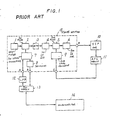
- FIG. 1 An example of a prior art channel selection apparatus of the type described above is illustrated in Fig. 1, in which the portion 15 enclosed by a broken-line outline is a tuner section, formed of an up-down converter double superhet circuit.
- the tuner section includes an input filter 1, a first mixer 2 and a first local oscillator 7.
- An input signal containing a number of television channels as described above is transferred through the input filter 1 to be mixed in the first mixer 2 with a local oscillator signal produced from the first local oscillator 7, to be thereby converted to a first IF signal.
- This first IF signal is transferred through a band-pass filter 3 and then amplified in a first IF amplifier 4, which produces an output signal that is supplied to a second mixer 5.
- a second local oscillator 9 produces a local oscillator signal which is mixed with the first IF signal in the second mixer 5, to thereby convert the first IF signal to a second IF signal.
- the second IF signal is then amplified in a second IF amplifier 6, whose output (generally referred to as the video IF signal) is applied to an output terminal D.
- both the first local oscillator 7 and the second local oscillator 9 are voltage-control oscillators.
- Numeral 8 denotes a prescaler, which executes frequency division of the output signal from the first local oscillator 7.
- Numeral 10 denotes a VIF (video IF) amplifier, and 11 an automatic frequency control (AFC) circuit.
- Numeral 12 denotes a LPF (low pass filter)
- 13 denotes a PLL (phase lock loop) circuit
- 14 denotes a microcomputer.
- this prior art channel selection apparatus is as follows.
- the video IF signal produced from the tuner section 15 is amplified in the video IF amplifier 10, and the resultant output signal from the video IF amplifier 10 is applied to the AFC circuit 11.
- the AFC circuit 11 thereby produces a frequency control voltage in accordance with the frequency of the video IF signal, which is supplied through an input terminal C of the tuner section 15 to control the frequency of oscillation of the second local oscillator 9. In this way, closed loop control is executed to stabilize the frequency of oscillation of the second local oscillator 9.
- the second local oscillator 9 is set at a fixed frequency of oscillation. However there is a possibility that this frequency will drift, due to changes in temperature etc., by up to 500 KHz, for example, whereas it is necessary that the frequency of oscillation of the second local oscillator 9 be stable to within ⁇ 50 KHz. If the frequency of oscillation should depart from that range, changes such as generation of spurious beat components will occur in the video IF signal produced from the apparatus, which will affect the displayed televison picture. For this reason it is preferable to employ an AFC loop to stabilize the frequency of oscillation of the second local oscillator 9 as described above.
- the first local oscillator 7 on the other hand must have a capability for varying the frequency of oscillation thereof, in order to select various channels contained in the input signal.
- Such alteration of the frequency of oscillation of the first local oscillator 7, i.e. channel tuning operation, is executed by varying a control voltage which is applied to the input terminal A of the tuner section 15. Since the frequency of oscillation of the first local oscillator 7 is high, and the changes which are made in that frequency in order to execute channel selection are relatively large, a PLL circuit 13 is used to stabilize and to control changes in that frequency of oscillation.
- the ' output signal from the first local oscillator-7 is frequency divided in the pre-scaler 8, and the resultant frequency-divided signal is applied from terminal B of the tuner section 15 to the PLL circuit 13.
- Tuning data to designate selection of a desired television channel, are produced from the microcomputer 14 in response to actuations of an input device such as a keyboard or a remote control unit (not shown in the drawings), and are transferrred to the PLL circuit 13.
- the PLL circuit 13 contains a frequency divider which executes frequency division of the output signal from the pre-scaler 8 by a division ratio 1/n, with this frequency division ratio being determined by the tuning data from the microcomputer 14.
- the resultant frequency-divided signal is compared in the PLL circuit 13 with a reference frequency, to detect any deviation of the frequency-divided signal, and a detection signal representing such a deviation is transferred through the low-pass filter 12 to the input terminal A of the tuner section 15 and hence supplied to the first local oscillator 7 as a frequency control voltage.
- the frequency of oscillation of the first local oscillator 7, which is a voltage-control oscillator, is thereby controlled such as to compensate for the aforementioned frequency deviation, i.e. closed-loop control fo the first local oscillator 7 is executed.
- Fig. 2 shows the AFC characteristic of the AFC circuit 11 in Fig. 1, i.e. the relationship between the frequency of the second IF signal applied from the video IF amplifier 10 and the resultant control voltage V c which is produced from the AFC circuit 11 and supplied to the second local oscillator 9.
- the output voltage V produced from the AFC circuit 11 might for example correspond to point 1 indicated on the characteristic of Fig. 2.
- the AFC circuit 11 can perform AFC operation to hold the second IF signal close to the standard value thereof, i.e. this represents the detection range for AFC control by the AFC circuit 11.
- detection means were provided for indicating to the microcomputer 14 that the second IF signal frequency is outside this window range, it could be arranged that the microcomputer 14 will supply control data to the PLL circuit 13 whereby one or more step changes in frequency of the frequency of oscillation of the first local oscillator 7 (and hence of the frequency of the second IF signal) are executed, until the window range W is entered.
- the microcomputer 14 could be notified accordingly, to thereby halt any further frequency stepping operations.
- a first step in frequency of the first local oscillator 7 would be executed to position 2
- a second frequency step would be executed to bring the voltage V c to position 3, which is within the window W. Frequency stepping would then be terminated.
- a channel selection apparatus comprises:
- an AFC control voltage produced from the AFC circuit is supplied to the second local oscillator, while when changeover of the AFC switch to a second condition thereof is executed, the AFC control voltage is supplied to a PLL circuit which includes the first local oscillator.
- the second local oscillator is supplied with a fixed level of control voltage, and AFC control of the first local oscillator is executed to adjust the oscillation frequency thereof such that a deviation of the transmission frequency of the input signal received by the apparatus from the center value of that IF frequency is compensated.
- the AFC control voltage serves to stabilize the frequency of oscillation of the second local oscillator.
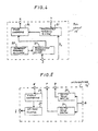
- Fig. 3 shows an embodiment of a channel selection apparatus according to the present invention.
- circuit blocks corresponding to blocks in the prior art example of Fig. 1 are indicated by corresponding reference numerals, and further description of these will be omitted.
- the embodiment of Fig. 3 differs from the prior art example of Fig. 1 by including an AFC switch 16, an analog switch 17, a fixed voltage source 18, and a resistive voltage divider formed of resistors 19 and 20 connected between a potential + B and ground potential.
- a PLL circuit 13' differs from the PLL circuit 13 of Fig. 13 by including an additional programmable frequency divider as described hereinafter
- a microcomputer 14' differs from the microcomputer 14 of Fig. 13 by including additional functions as described hereinafter.
- the analog switch 17 is provided with a set of control electrodes 17a, 17b, 17c and 17d, which respectively selectively establish a closed or open circuit condition between pairs of switch contacts designated as a pair 1, 2, a pairo 3, 4, a pair 5, 6 and a pair 7, 8, in accordance with logic level potentials applied to the electrodes 17a to 17c.
- the voltage source 18 applies a reference voltage to the contact 0 of switch 17, and the junction of resistors 19 and 20 is connected to contact 8
- Contacts 2 and 3 of switch 17 are connected in common to the second local oscillator 9, for supplying a frequency control voltage thereto.
- Contacts 4, 6 and 7 of switch 17 are coupled in common to receive _a a frequency control voltage V c produced from the AFC circuit 11, while contact 5 is unused.
- Fig. 4 shows details of the internal configuration of the PLL circuit 13'
- Fig. 5 is a functional block diagram showing the specific features of the microcompouter 14' which are special to the present invention.
- numeral 21 denotes a first programmable frequency divider whose frequency division ratio is controlled by channel selection data D s supled (via the broken-line path) from the microcomputer 14'.
- Numeral 22 denotes a reference frequency oscillator.
- the frequency division ratio of the programmable frequency divider 23 can be adjusted by frequency adjustment data D a which are transferred to an input terminal J from the microcomputer 14'. More specifically, the frequency adjustment data D a can produce step changes in the frequency division ratio of the programmable frequency divider 23, and hence result in corresponding step changes in the output from the phase comparison signal, which produce corresponding step changes in the frequency of oscillation of the first local oscillator 7.
- 25 and 26 denote respective switching drive sections for applying control voltages from terminals F and G respectively to the electrodes 17a, 17d and electrodes 17b, 17c respectively of the analog switch 17, which determine the closed and open states of the corresponding switch contact pairs.
- a window comparator 27 serves to detect when the input voltage applied to a terminal E is above or below the window range W shown in Fig. 2. A control signal is thereby produced from the comparator 27 to indicate the result of this detection.
- An up-down counter 28 responds to this control signal from the window comparator 27 by incrementing or decrementing a count value therein, or holding the count value unchanged, in accordance with the status of that control signal.
- the frequency adjustment data D a applied from the up-down counter 28 to the PLL circuit 13' as described hereinafter, in accordance with up or down counting operation by the up-down counter 28.
- microcomputer 14' which are novel to the present invention are described herein, and that various other functions are executed by the microcomputer 14' such as generation of channel selection data D s shown in Fig. 3, to be supplied to the programmable frequency divider 21 of the PLL circuit 13'.
- the AFC switch 16 is set in a first condition, i.e. an OFF condition, whereby a specific logic level potential (assumed in the following to be the L level potential) is applied from the AFC switch 16 to an input terminal H of the microcomputer 14'.
- the switch drive section 25 produces a control voltage at the L level from terminal G
- the switch drive section 26 produces a control voltage at the H level from output terminal F of the microcomputer 14'.
- a conducting condition is established between the contacts 3 , 4 and between the contacts 5, 6, respectively, while an open circuit condition is established between the contacts 1, 2 and between the contacts 7, 8 respectively.
- the control voltage V c produced from the AFC circuit 11 is thereby transferred through switch contacts 4, 3 to the input terminal C of the tuner section 15, to control the frequency of oscillation of the second local oscillator 9.
- the frequency of oscillation of the second local oscillator 9 is thereby held .stable.
- the voltage produced at the junction of resistors 19 and 20 is applied through terminal E of the microcomputer 14' to an input of the window comparator 27. That voltage is predetermined to be within the window range W shown in Fig. 2 and described above, so that no control signal is produced by the comparator 27 and hence no counting operations are executed by the up-down counter 28, and no change occurs in the data D a from the up-down counter 28 applied to the PLL circuit 13'.
- the frequency of oscillation of the first local oscillator 7 is stabilized by a closed PLL control loop formed of the combination of the PLL circuit 13', the pre-scaler 8, and the low-pass filter 12, with the frequency division ratio of the programmable frequency divider 23 in the PLL circuit 13' being held fixed, and with the frequency division ratio of the programmable frequency divider 21 being determined by channel selection data D supplied from the microcomputer 14'.
- the frequency of oscillation of the first local oscillator 7 is held fixed until a channel selection operation is executed by varying the channel selection data D s supplied to the PLL circuit 13'.
- the operation when the AFC switch 16 is set to the ON state is as follows.
- an H level voltage is applied from the AFC switch 16 to the switch drive section 25 and the switch drive section 26 of the microcomputer 14',
- the switch drive section 25 produces an H level control signal
- the switch drive section 26 an L level control signal, whereby a conducting condition is established between contacts 1, 2 and between contacts 7, 8 of the analog switch 17, and an open-circuit condition is established between contacts 3, 4 and between contacts 5, 6.
- the AFC control voltage produced from the AFC circuit 11 is transferred through the contacts 7, 8 of the analog switch 17 to the input terminal E of the microcomputer 14' and hence is applied to an input of the window comparator 27. In this condition.
- the resistors 19 and 20 are in effect connected in parallel across the frequency control voltage V c , so that the effective gain of the AFC circuit 11 is modified, i.e. the frequency/voltage characteristic of that circuit (as seen from the input of comparator 27) is modified such that the rate of change of control voltage V with respect to frequency changes is lowered.
- the reference voltage VR 1 from voltage source 18 is transferred as a frequency control voltage to the second local oscillator 9, whereby the frequency of oscillation of the second local oscillator 9 is held fixed at a predetermined nominal value, which is close to the center of the control range of the AFC circuit 11.
- the frequency of the second IF signal from the second IF amplifier 6 will deviate substantially from the nominal value of that frequency, since the frequency of oscillation of the second local oscillator 9 is held fixed. That nominal value corresponds to the central value of the frequency f in-the characteristic of Fig. 2, so that the control voltage V c from the AFC circuit 11 will be outside the window range W, i.e. will be higher than the value V1 of lower than the value V2 shown in Fig. 2.
- the control voltage V c is higher than V1
- an output signal is applied from the window comparator 27 to the up-down counter 28 which initiates counting up by the up-down counter 28 of a clock signal (not shown in the drawings).
- the data D a applied from terminal I of the microcomputer 14' to the programmable frequency divider 23 of the PLL circuit 13' produces a step change in the frequency division ratio of the programmable frequency divider 23 such as to produce a corresponding change in the frequency of oscillation of the first local oscillator 7 which results in a step reduction in the second IF signal frequency, e.g. a step reduction Af as indicated in Fig. 2.
- the second IF signal frequency will be brought within the window range W, whereupon the output signal from the window comparator 27 terminates counting by the up-down counter 28, thereby causing the output data from the up-down counter 28 to terminate further step changes in the frequency of oscillation of the first local oscillator 7.
- the control voltage V c is detected as being lower than the value V2 by the window comparator 27, then an output signal is applied from the window comparator 27 to the up-down counter 28 which initiates counting down by the up-down counter 28 of the aforementioned clock signal.
- the data D a from the microcomputer 14' produces a step change in the frequency division ratio of the programmable frequency divider 23 such as to result in a step decrement of the second IF signal by the amount f.
- the frequency of oscillation of the first local oscillator is brought to a value which enables automatic frequency control of the second local oscillator to be initiated, i.e. follow-up control of the first local oscillator is performed such as to compensate for an offset in the transmission frequency of the selected channel.
- the frequency of oscillation of the second local oscillator 9 is held at a fixed value by the voltage VR, applied from the reference voltage source 18.
- the level of VR is made substantially identical to the center value of the control range of the AFC voltage V c produced from the AFC circuit 11 during normal AFC control of the second local oscillator 9.
- the frequency of oscillation of the second local oscillator 9 remains substantially unchanged when the AFC switch 16 condition is changed to the ON state to initiate the follow-up operation described above.
- the AFC switch 16 Upon completion of this frequency follow-up operation, the AFC switch 16 is returned to the OFF state thereof, whereupon the switch drive section 25 and switch drive section 26 of the microcomputer 14' control the analog switch 17 such that an open-circuit is again established between the contacts of contact pair 1, 2 and contact pair while a conducting condition is established between the contact pair 3, 4 and contact pair 5, 6.
- the control voltage V c from the AFC circuit 11 is thereby once more applied to control the frequency of oscillation of the second local oscillator 9 to thereby stabilize that frequency of oscillation by closed-loop control.
- a time of approximately 200 mS is required from the point at which the AFC switch 16 is set in the ON state to begin controlling the PLL circuit 13' in accordance with the control voltage V c from the AFC circuit 11 until the point at which the frequency follow-up operation described above is completed. It would be possible to control the changeover operations of the analog switch 17 based upon the output signal from the window comparator 27, i.e. to detect the completion of the frequency follow-up operation based on the level of that output signal and to control the analog switch 17 accordingly such as to return to AFC control of the second local oscillator 9.
- the system can be configured such that, after a time of 200 mS has elapsed following the initiation of frequency follow-up control of the 13' by the control signal V c . the analog switch 17 is automatically reset to restore AFC control of the second local oscillator 9 by signal V c (i.e. switch 16 is automatically returned to the OFF state).
- the AFC switch 16 could be a switch which can be manually set in the ON state. However it is also possible to arrange that the AFC switch 16 is automatically set in the ON state at the time of a channel switching operation to select a new channel, and to thereafter remain in the ON state for a 200 mS interval, while being held in the OFF state at all other times.
- a control voltage produced from an AFC circuit in accordance with the frequency of a video IF signal that is outputted from the tuner is utilized to stabilize the frequency of oscillation of a second local oscillator of the tuner during normal operation.
- the AFC control voltage is utilized to adjust the frequency of oscillation of the first local oscillator of the tuner such as to compensate for any offset in the transmission frequency of the selected channel.
- control of the frequency of oscillation of the second local oscillator by the AFC control voltage is resumed.
- such a channel selection apparatus enables highly stable frequency control to be maintained during normal operation, while enabling a channel to be reliably selected and a satisfactory television picture derived therefrom, even if the transmission frequency of that channel deviates substantially from the nominal channel frequency.
- a channel selection apparatus having a double superhet tuner section (15) for converting one of a plurality of television channesl contained in an input signal to a fixedly predetermined channel includes an AFC circuit (11) for producing a frequency control voltage to execute closed-loop frequency control of the second local oscillator (5) of the tuner section while an AFC switch (16) is set in a first contition, whereas when the AFC swtich is set in a second condition, a fixed frequency control voltage is applied to the second local oscillator and the frequency control voltage is applied to adjustt the oscillation frequency of the first local oscillator (2) of the tuner section such as to compensate for any offset in the transmission frequency of the currently selected channel.
Landscapes
- Channel Selection Circuits, Automatic Tuning Circuits (AREA)
- Superheterodyne Receivers (AREA)
- Television Receiver Circuits (AREA)
Applications Claiming Priority (2)
| Application Number | Priority Date | Filing Date | Title |
|---|---|---|---|
| JP313954/86 | 1986-12-24 | ||
| JP61313954A JPS63161718A (ja) | 1986-12-24 | 1986-12-24 | 選局装置 |
Publications (3)
| Publication Number | Publication Date |
|---|---|
| EP0273389A2 true EP0273389A2 (de) | 1988-07-06 |
| EP0273389A3 EP0273389A3 (en) | 1989-01-25 |
| EP0273389B1 EP0273389B1 (de) | 1992-09-09 |
Family
ID=18047491
Family Applications (1)
| Application Number | Title | Priority Date | Filing Date |
|---|---|---|---|
| EP87119134A Expired - Lifetime EP0273389B1 (de) | 1986-12-24 | 1987-12-23 | Kanalwahlgerät mit selbsttätiger Kompensierung des Sendefrequenzfehlers |
Country Status (5)
| Country | Link |
|---|---|
| US (1) | US4817195A (de) |
| EP (1) | EP0273389B1 (de) |
| JP (1) | JPS63161718A (de) |
| KR (1) | KR910001375B1 (de) |
| DE (1) | DE3781655T2 (de) |
Cited By (1)
| Publication number | Priority date | Publication date | Assignee | Title |
|---|---|---|---|---|
| EP0352853A1 (de) * | 1988-07-26 | 1990-01-31 | Koninklijke Philips Electronics N.V. | Fernsehempfänger mit einer Abstimmschaltung, die eine Frequenzsyntheseschaltung aufweist |
Families Citing this family (20)
| Publication number | Priority date | Publication date | Assignee | Title |
|---|---|---|---|---|
| FI85636C (fi) * | 1988-08-19 | 1992-05-11 | Nokia Mobira Oy | Foerfarande och koppling foer automatisk, pao en raeknare baserad reglering av frekvensen i en radiotelefon. |
| US5245437A (en) * | 1988-12-29 | 1993-09-14 | Samsung Electronics Co., Ltd. | Method for selecting channels in a video system using a national television system committee (NTSC) system |
| DE58909454D1 (de) * | 1989-07-06 | 1995-11-02 | Itt Ind Gmbh Deutsche | Digitale Steuerschaltung für Abstimmsysteme. |
| JPH0648778B2 (ja) * | 1989-09-29 | 1994-06-22 | 三洋電機株式会社 | 衛星放送受信装置のafc方法 |
| JPH04111540A (ja) * | 1990-08-30 | 1992-04-13 | Matsushita Electric Ind Co Ltd | ダブルスーパチューナ |
| JPH05152903A (ja) * | 1991-06-29 | 1993-06-18 | Nec Corp | 移動無線機 |
| US5311318A (en) * | 1992-08-17 | 1994-05-10 | Zenith Electronics Corporation | Double conversion digital tuning system using separate digital numbers for controlling the local oscillators |
| JPH0746150A (ja) * | 1993-07-31 | 1995-02-14 | Nec Corp | 無線選択呼出受信機 |
| DE4332161A1 (de) * | 1993-09-22 | 1995-03-23 | Thomson Brandt Gmbh | Hochfrequenzempfänger |
| US5663989A (en) * | 1993-10-28 | 1997-09-02 | Plessey Semiconductors Limited | Control arrangements for digital radio receivers |
| US5552838A (en) * | 1993-12-24 | 1996-09-03 | Kabushiki Kaisha Toshiba | Apparatus for tuning offset signals by controlling a tuner based on a difference in frequency of signals tuned by that tuner |
| US5486866A (en) * | 1994-06-21 | 1996-01-23 | Thomson Consumer Electronics, Inc. | Oscillator free run frequency setting by data bus control |
| US5774195A (en) * | 1995-01-24 | 1998-06-30 | Kabushiki Kaisha Toshiba | Broadcasting system discriminating television receiver for differentiating between analog and digital telecast signals |
| KR100401242B1 (ko) * | 1996-07-26 | 2003-12-24 | 엘지이노텍 주식회사 | 위성방송수신용 튜너 |
| JP3360004B2 (ja) * | 1997-03-20 | 2002-12-24 | 松下電器産業株式会社 | 無線受信装置 |
| US6163687A (en) * | 1997-07-22 | 2000-12-19 | Intel Corporation | Tuning module for a dual frequency PLL synthesized tuner |
| US6567654B1 (en) * | 1999-10-28 | 2003-05-20 | Matsushita Electronic Components De Baja California, S.A. De C.V. | Elimination of spurious signals in double conversion tuner using a dynamic intermediate frequency and a preselected crystal reference frequency |
| US6704555B2 (en) * | 2001-01-09 | 2004-03-09 | Qualcomm, Incorporated | Apparatus and method for calibrating local oscillation frequency in wireless communications |
| US7543393B2 (en) * | 2003-12-16 | 2009-06-09 | Renishaw Plc | Method of calibrating a scanning system |
| FR2867926B1 (fr) * | 2004-03-16 | 2006-07-07 | St Microelectronics Sa | Procede et systeme de reception satellitaire |
Family Cites Families (11)
| Publication number | Priority date | Publication date | Assignee | Title |
|---|---|---|---|---|
| US4365349A (en) * | 1980-02-01 | 1982-12-21 | Nippon Gakki Seizo Kabushiki Kaisha | Radio receiver having phase locked loop and automatic frequency control loop for stably maintaining local oscillator frequency of voltage-controlled local oscillator |
| JPS57119512A (en) * | 1981-01-19 | 1982-07-26 | Toshiba Corp | Frequency control system |
| JPS5957534A (ja) * | 1982-09-27 | 1984-04-03 | Alps Electric Co Ltd | 衛星放送用受信器の屋内ユニツト |
| US4575761A (en) * | 1983-04-28 | 1986-03-11 | Rca Corporation | AFT arrangement for a double conversion tuner |
| WO1984004637A1 (en) * | 1983-05-16 | 1984-11-22 | Motorola Inc | A receiver system for eliminating self-quieting spurious responses |
| US4581643A (en) * | 1983-07-25 | 1986-04-08 | Rca Corporation | Double conversion television tuner with frequency response control provisions |
| US4627100A (en) * | 1984-12-28 | 1986-12-02 | Regency Electronics, Inc. | Wide band radio receiver |
| JPH03761Y2 (de) * | 1985-02-28 | 1991-01-11 | ||
| JPS62117408A (ja) * | 1985-11-18 | 1987-05-28 | Casio Comput Co Ltd | オ−トチユ−ニング装置 |
| US4727591A (en) * | 1986-09-04 | 1988-02-23 | Arvin Industries, Inc. | Microprocessor controlled tuning system |
| US4703520A (en) * | 1986-10-31 | 1987-10-27 | Motorola, Inc. | Radio transceiver having an adaptive reference oscillator |
-
1986
- 1986-12-24 JP JP61313954A patent/JPS63161718A/ja active Pending
-
1987
- 1987-12-23 DE DE8787119134T patent/DE3781655T2/de not_active Expired - Fee Related
- 1987-12-23 EP EP87119134A patent/EP0273389B1/de not_active Expired - Lifetime
- 1987-12-23 US US07/137,148 patent/US4817195A/en not_active Expired - Lifetime
- 1987-12-23 KR KR1019870014842A patent/KR910001375B1/ko not_active Expired
Cited By (1)
| Publication number | Priority date | Publication date | Assignee | Title |
|---|---|---|---|---|
| EP0352853A1 (de) * | 1988-07-26 | 1990-01-31 | Koninklijke Philips Electronics N.V. | Fernsehempfänger mit einer Abstimmschaltung, die eine Frequenzsyntheseschaltung aufweist |
Also Published As
| Publication number | Publication date |
|---|---|
| JPS63161718A (ja) | 1988-07-05 |
| EP0273389B1 (de) | 1992-09-09 |
| DE3781655D1 (de) | 1992-10-15 |
| KR880008524A (ko) | 1988-08-31 |
| KR910001375B1 (ko) | 1991-03-04 |
| DE3781655T2 (de) | 1993-01-28 |
| EP0273389A3 (en) | 1989-01-25 |
| US4817195A (en) | 1989-03-28 |
Similar Documents
| Publication | Publication Date | Title |
|---|---|---|
| US4817195A (en) | Channel selection apparatus having automatic frequency compensation for transmission frequency error | |
| US4575761A (en) | AFT arrangement for a double conversion tuner | |
| US4709406A (en) | A.F.C. system for broad-band FM receiver | |
| US4271530A (en) | Receiver having a frequency synthesizing circuit | |
| US4374437A (en) | Variable ramp speed TV tuning system for rapid channel tuning | |
| CA1183621A (en) | Tuning apparatus of phase-locked loop type | |
| JPS6350110A (ja) | 掃引受信機の受信感度制御方式 | |
| EP0779710A2 (de) | Automatische Frequenzregelungsschaltung | |
| US3821650A (en) | Phase lock loop electronic tuning system | |
| US4459560A (en) | Plural phase locked loop frequency synthesizer | |
| US4488123A (en) | Frequency synthesizer | |
| US5203032A (en) | Station selecting apparatus | |
| JPS5829655B2 (ja) | テレビジヨン受像機の同調装置 | |
| US4245351A (en) | AFT Arrangement for a phase locked loop tuning system | |
| US4317228A (en) | Television receiver having multiplexed phase lock loop tuning system | |
| JPS5925526B2 (ja) | 選局装置 | |
| JPS5924191Y2 (ja) | シンセサイザ−受信機のafc回路 | |
| JPH0475686B2 (de) | ||
| JPH0221716A (ja) | 選局装置 | |
| JPS5883446A (ja) | 受信機 | |
| JPS6246337Y2 (de) | ||
| JPH0349472Y2 (de) | ||
| JP2733089B2 (ja) | 周波数誤差検出回路 | |
| JPS5942760Y2 (ja) | シンセサイザ方式選局装置 | |
| JP3033049B2 (ja) | Dcfm回路の周波数ドリフト補正回路 |
Legal Events
| Date | Code | Title | Description |
|---|---|---|---|
| PUAI | Public reference made under article 153(3) epc to a published international application that has entered the european phase |
Free format text: ORIGINAL CODE: 0009012 |
|
| 17P | Request for examination filed |
Effective date: 19871223 |
|
| AK | Designated contracting states |
Kind code of ref document: A2 Designated state(s): DE FR GB |
|
| PUAL | Search report despatched |
Free format text: ORIGINAL CODE: 0009013 |
|
| AK | Designated contracting states |
Kind code of ref document: A3 Designated state(s): DE FR GB |
|
| 17Q | First examination report despatched |
Effective date: 19910124 |
|
| GRAA | (expected) grant |
Free format text: ORIGINAL CODE: 0009210 |
|
| AK | Designated contracting states |
Kind code of ref document: B1 Designated state(s): DE FR GB |
|
| REF | Corresponds to: |
Ref document number: 3781655 Country of ref document: DE Date of ref document: 19921015 |
|
| ET | Fr: translation filed | ||
| PLBE | No opposition filed within time limit |
Free format text: ORIGINAL CODE: 0009261 |
|
| STAA | Information on the status of an ep patent application or granted ep patent |
Free format text: STATUS: NO OPPOSITION FILED WITHIN TIME LIMIT |
|
| 26N | No opposition filed | ||
| REG | Reference to a national code |
Ref country code: GB Ref legal event code: 746 Effective date: 19950928 |
|
| REG | Reference to a national code |
Ref country code: FR Ref legal event code: D6 |
|
| PGFP | Annual fee paid to national office [announced via postgrant information from national office to epo] |
Ref country code: FR Payment date: 19961211 Year of fee payment: 10 |
|
| PGFP | Annual fee paid to national office [announced via postgrant information from national office to epo] |
Ref country code: GB Payment date: 19961216 Year of fee payment: 10 |
|
| PGFP | Annual fee paid to national office [announced via postgrant information from national office to epo] |
Ref country code: DE Payment date: 19961231 Year of fee payment: 10 |
|
| PG25 | Lapsed in a contracting state [announced via postgrant information from national office to epo] |
Ref country code: GB Free format text: LAPSE BECAUSE OF NON-PAYMENT OF DUE FEES Effective date: 19971223 |
|
| PG25 | Lapsed in a contracting state [announced via postgrant information from national office to epo] |
Ref country code: FR Free format text: THE PATENT HAS BEEN ANNULLED BY A DECISION OF A NATIONAL AUTHORITY Effective date: 19971231 |
|
| GBPC | Gb: european patent ceased through non-payment of renewal fee |
Effective date: 19971223 |
|
| PG25 | Lapsed in a contracting state [announced via postgrant information from national office to epo] |
Ref country code: DE Free format text: LAPSE BECAUSE OF NON-PAYMENT OF DUE FEES Effective date: 19980901 |
|
| REG | Reference to a national code |
Ref country code: FR Ref legal event code: ST |